I haven’t finished my LR2 build yet; in fact my shop still has no power, lights, insulation etc so this is all academic for now, but among other things, I will want to use a CNC system like the LR2 to cut 2D plywood parts that will fit together to create a 3D body buck from which I can create fiberglass car body panels.
The car chassis will be a 4130 alloy tube space frame, which will involve a lot of tube notching/coping/fishmouthing. I also intend to use the LR2 MPCNC router to cut plywood sheets precisely with perforations and register tabs that will puzzle together to locate 4130 chromoly tubes (and other things) in space relative to each other precisely for welding. With as many tubes as I will need to cut, I would like to automate the process because I am a disaster with either a grinder or a hole saw, and a CNC can be more accurate than me using my harbor freight plasma cutter. Every little pause, shake, tremble etc when I am plasma cutting, seems to telegraph through into the cut quality.
I am still thinking through the work flow, but until I am really in the shop trying it, I won’t really have that nailed down. I intend to use an SSR to start and stop the plasma torch, triggered via one of the hot end outputs (in Marlin I put the hot ends in “bang bang” mode for this). However, the part of this that I have become obsessed with, is the feed mechanism that will feed and rotate the tube relative to the plasma torch. I wanted to describe to everyone what I am trying, in case anyone is thinking of going down the same path. This could either be useful to someone, or simply a cautionary tale, so here goes!
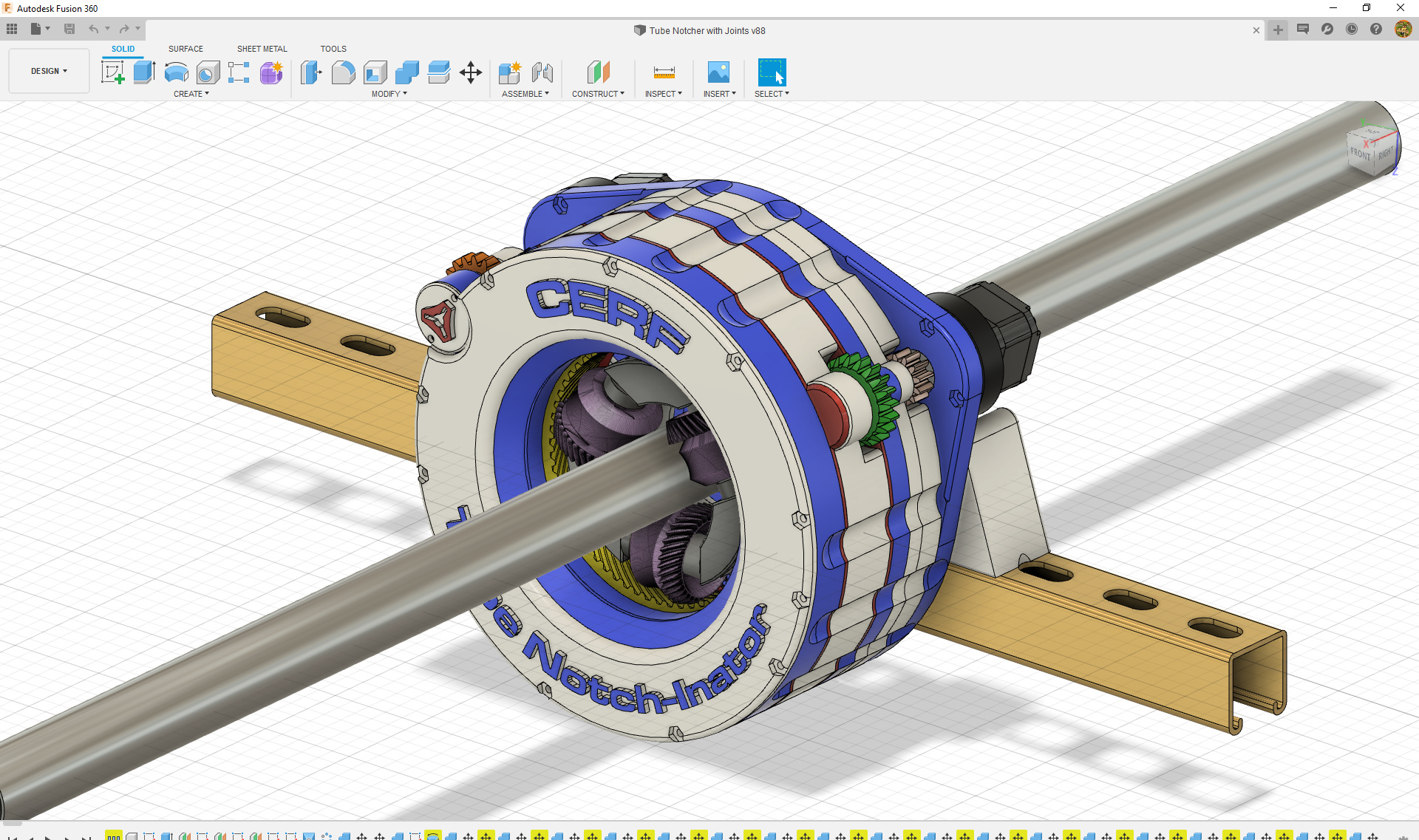
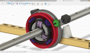
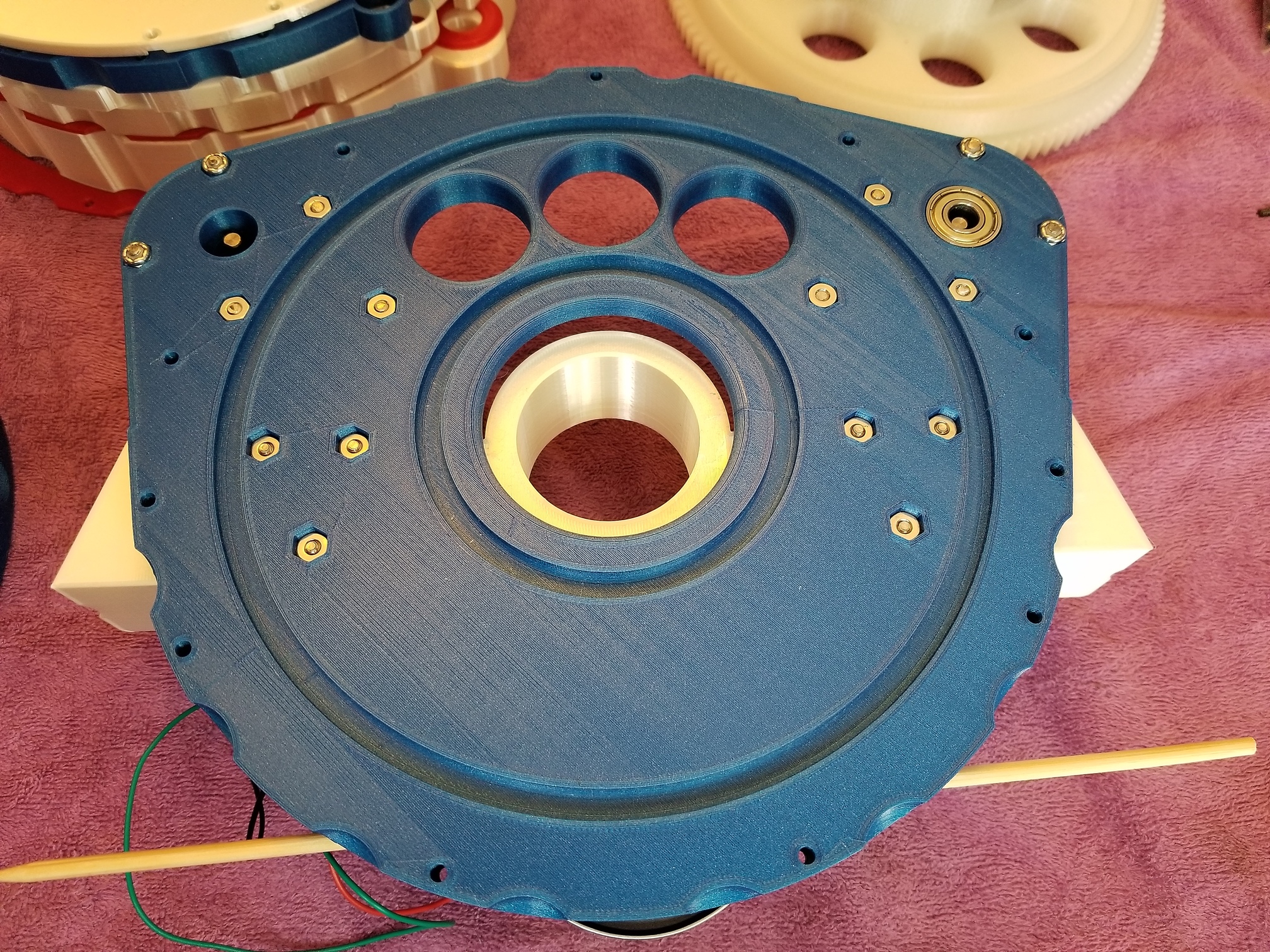
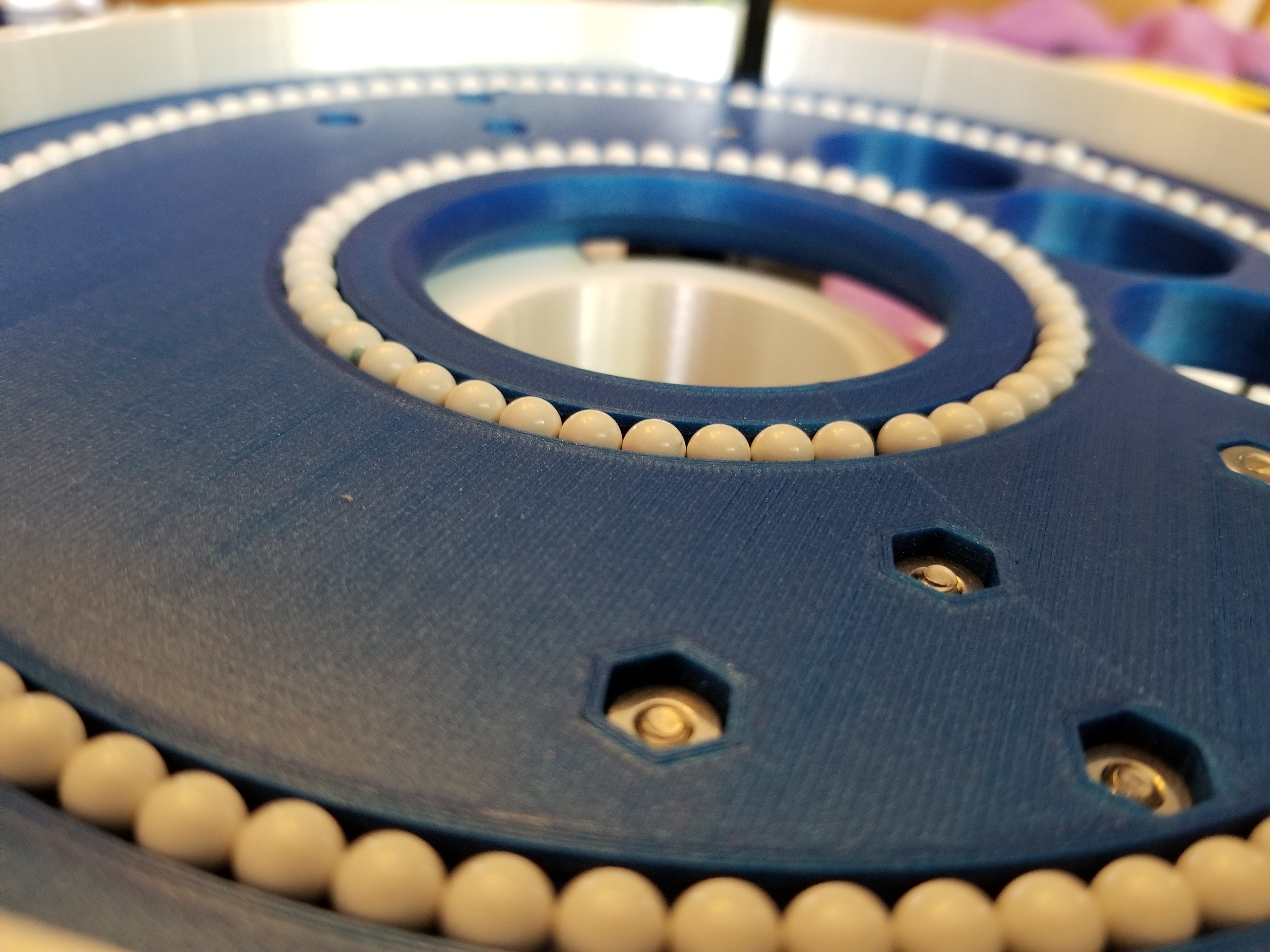
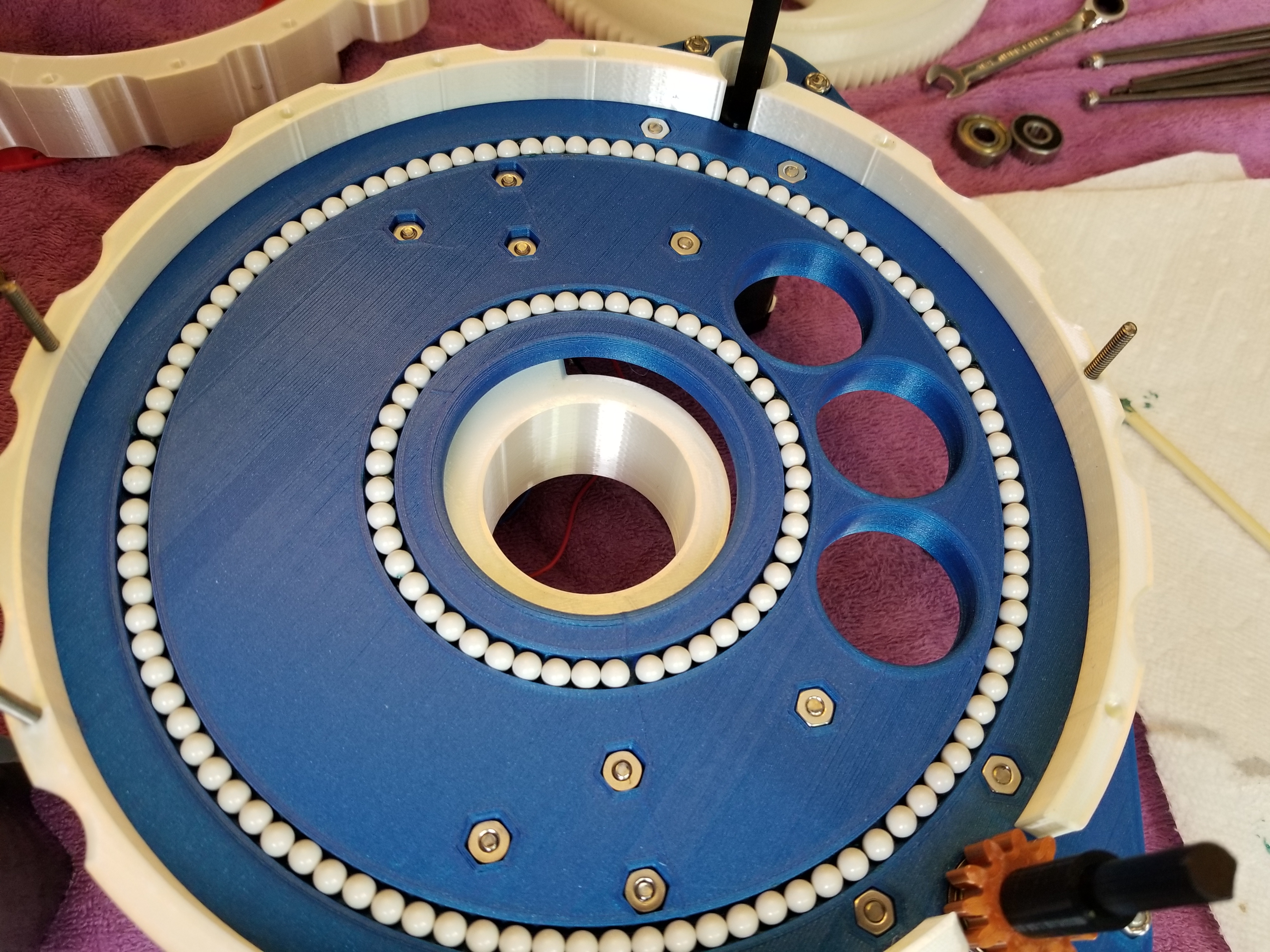
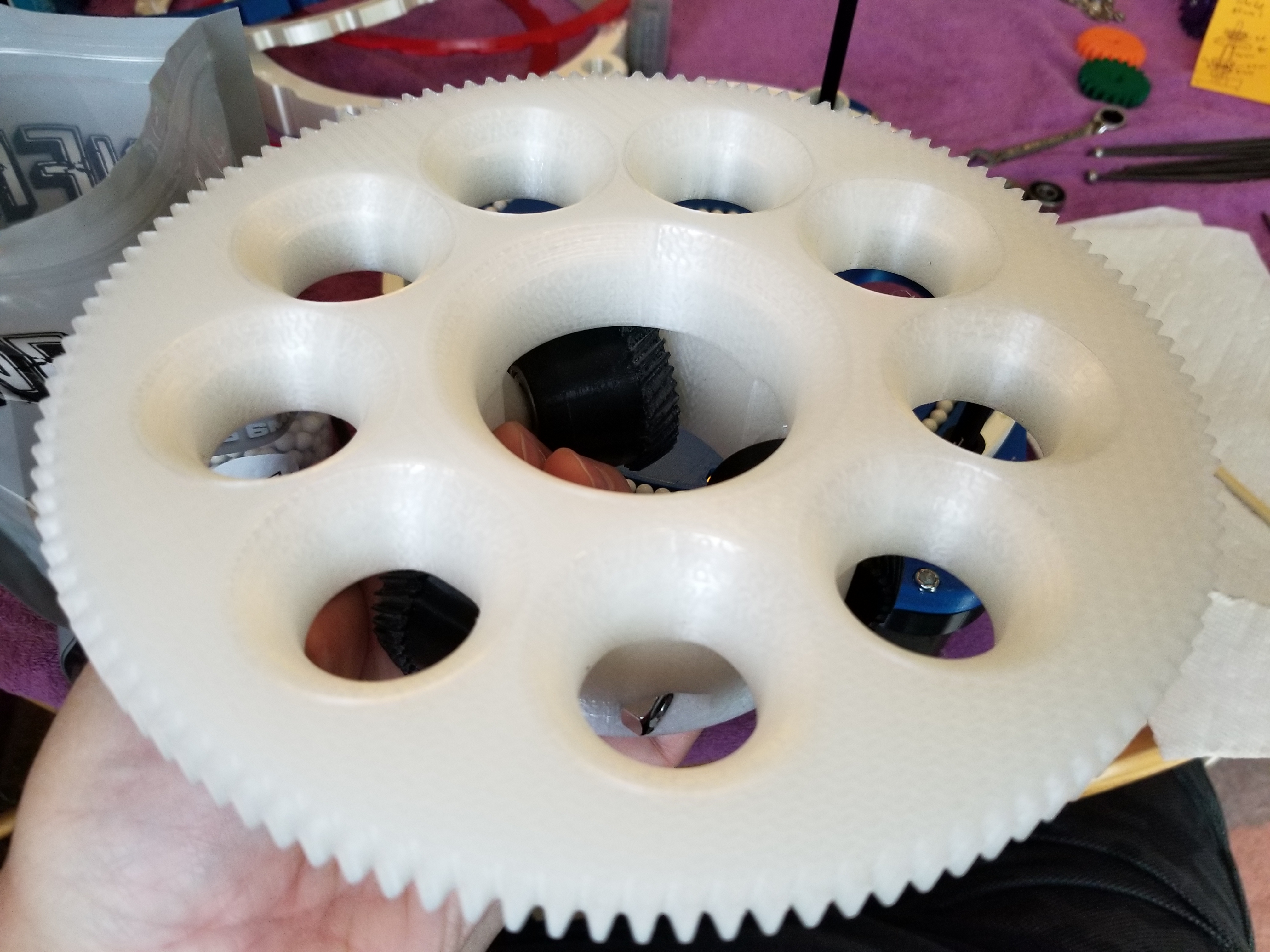
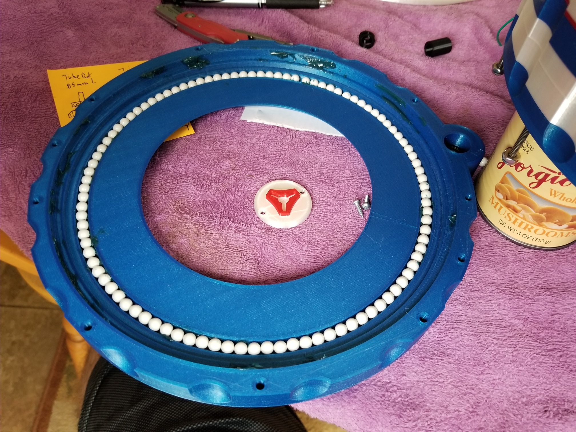
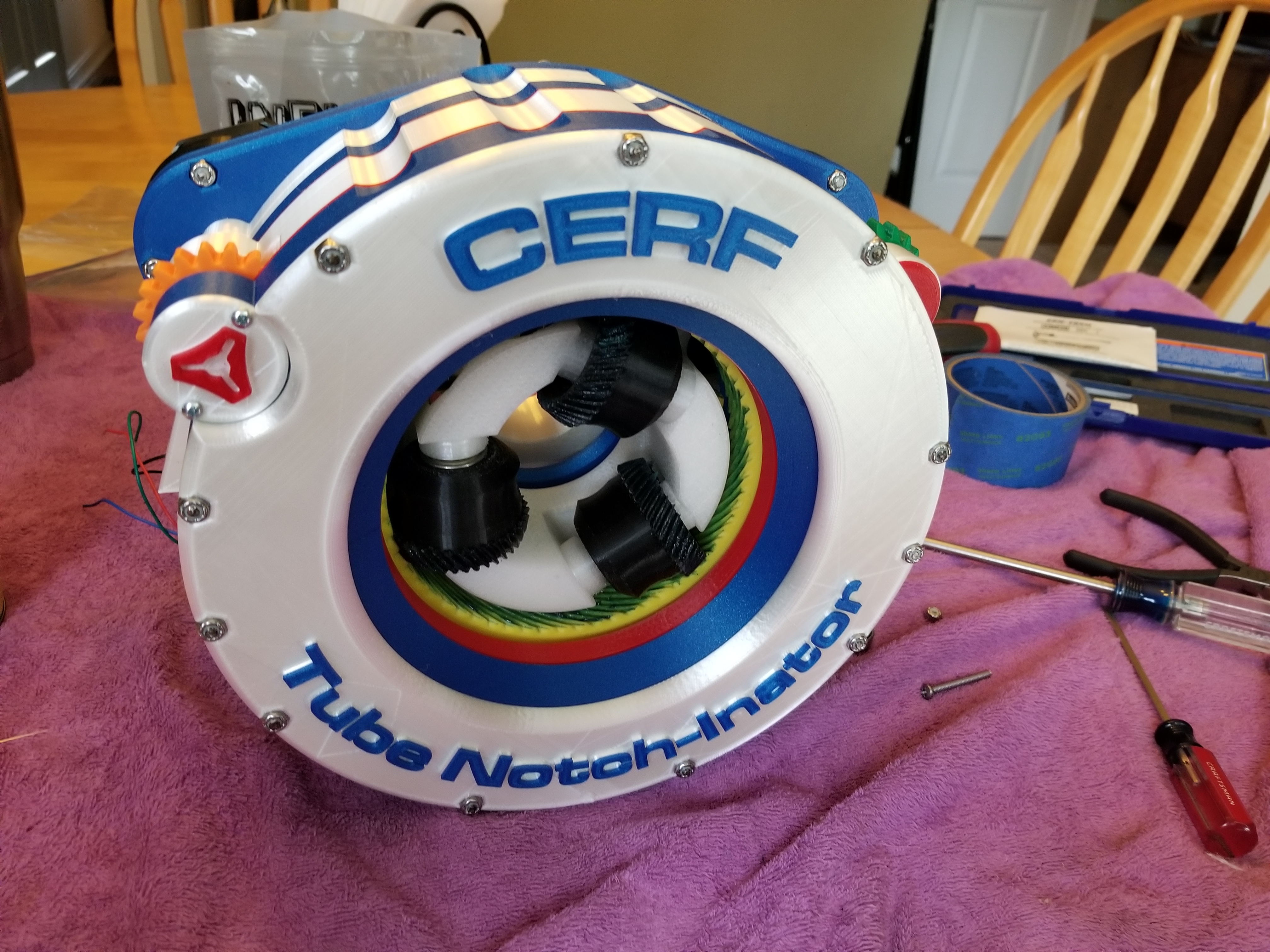
This is what I came up with, built in Fusion 360. It uses a handful of 608 bearings, and a metric holy handful of those little 6mm plastic balls in little races to locate the parts and keep everything aligned. I picked up the 608 bearings from Ryan’s designs, and first saw the plastic BBs in a YouTube video from Some Old Guy Coding where he was walking through a build of a printed Slewing drive.
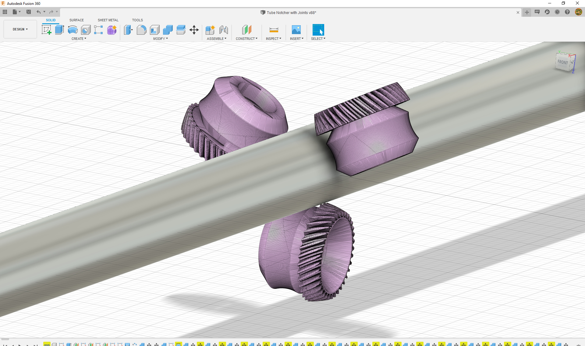
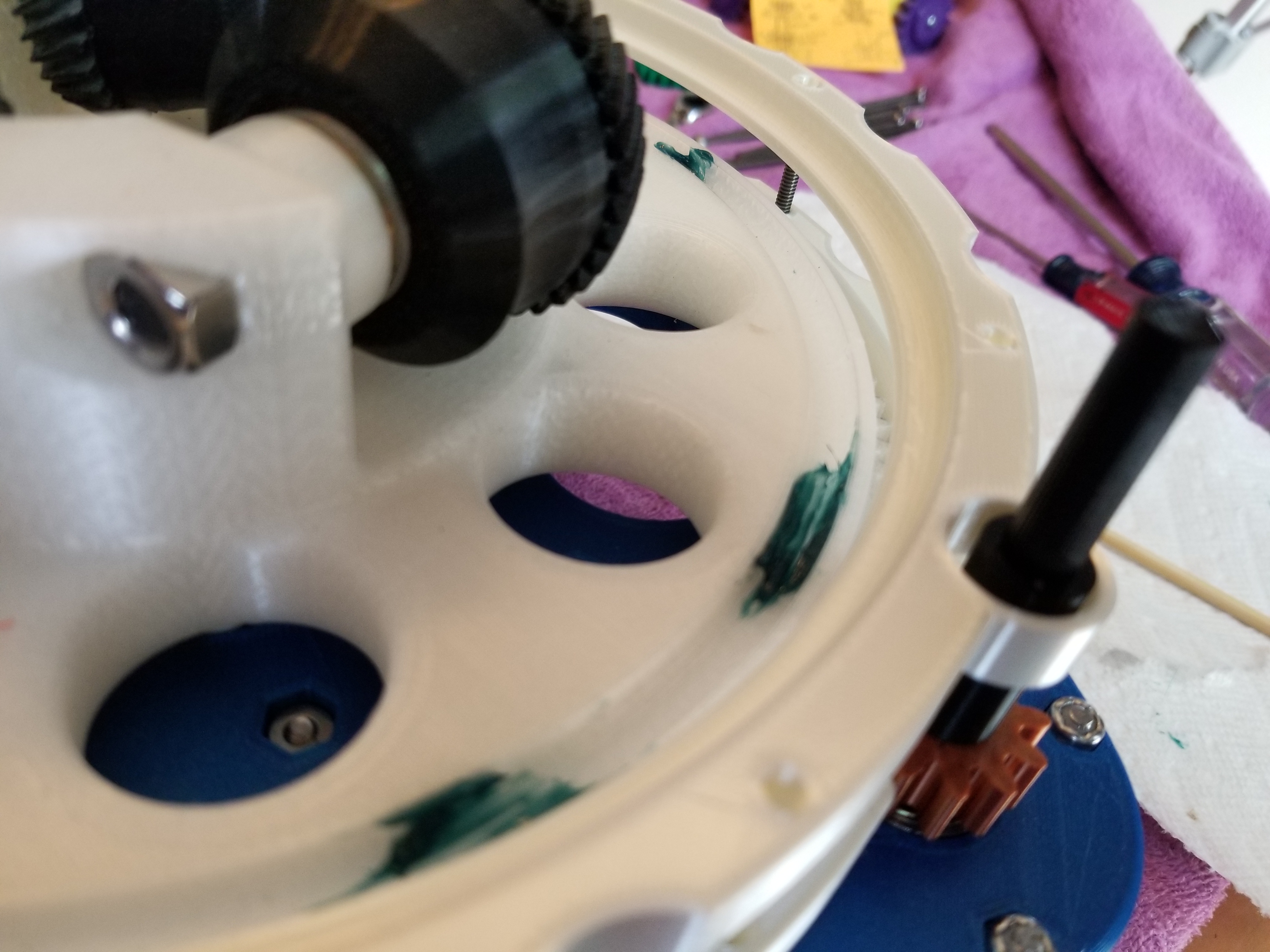
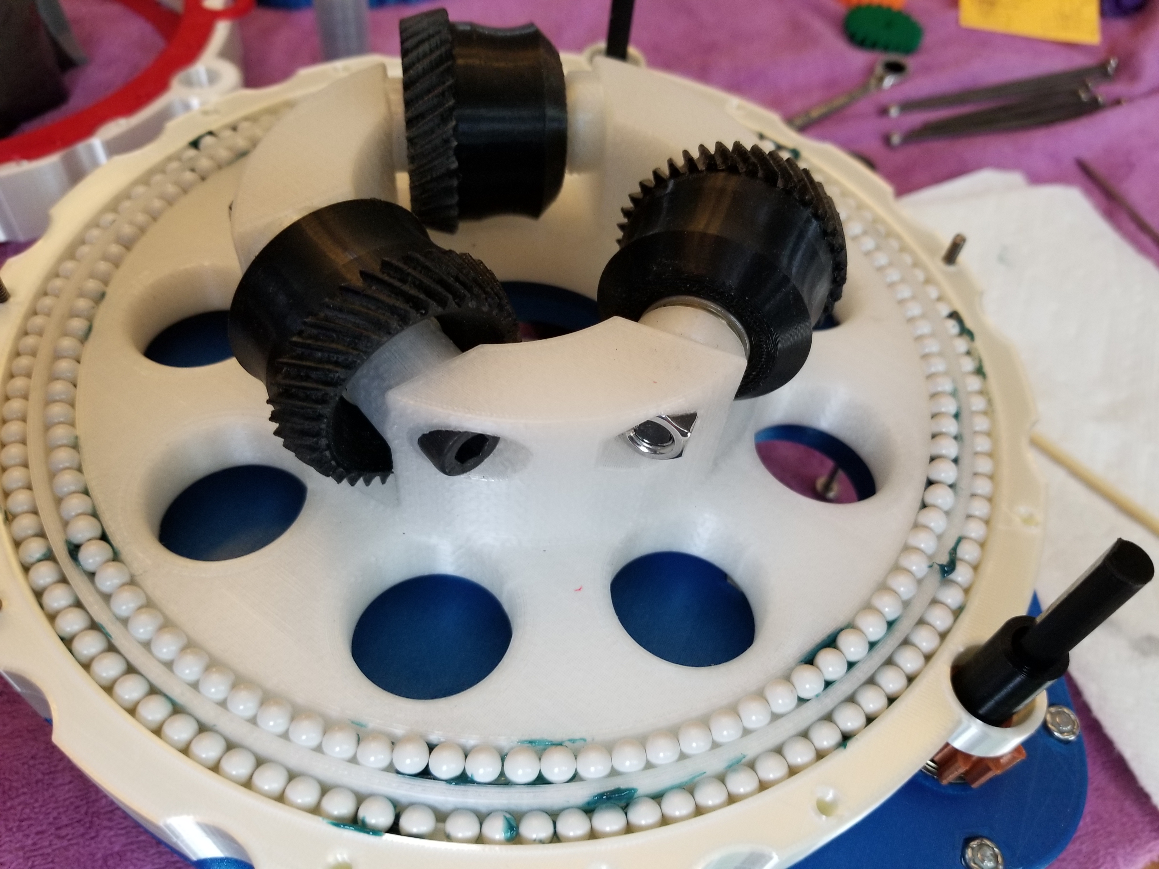
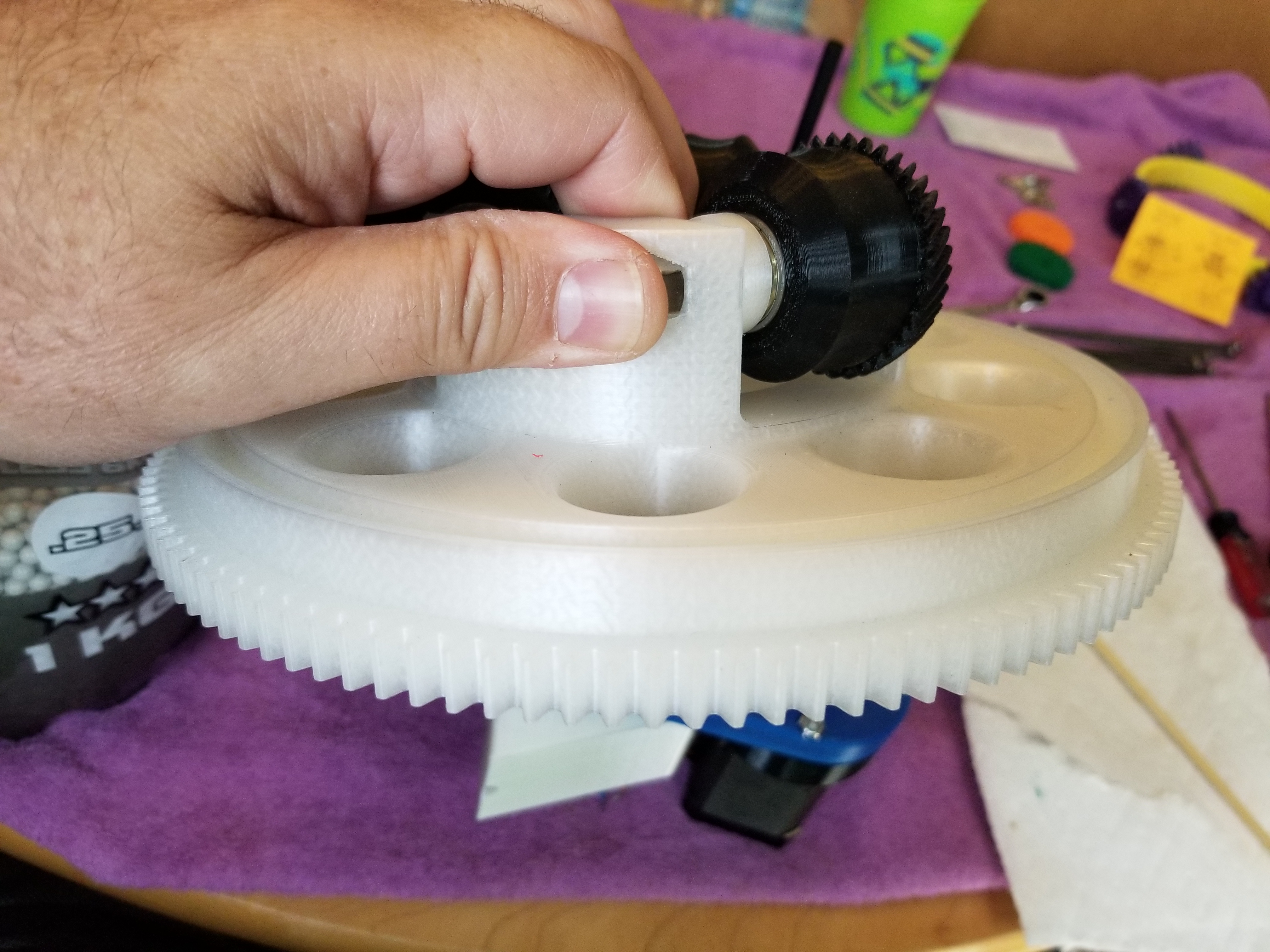
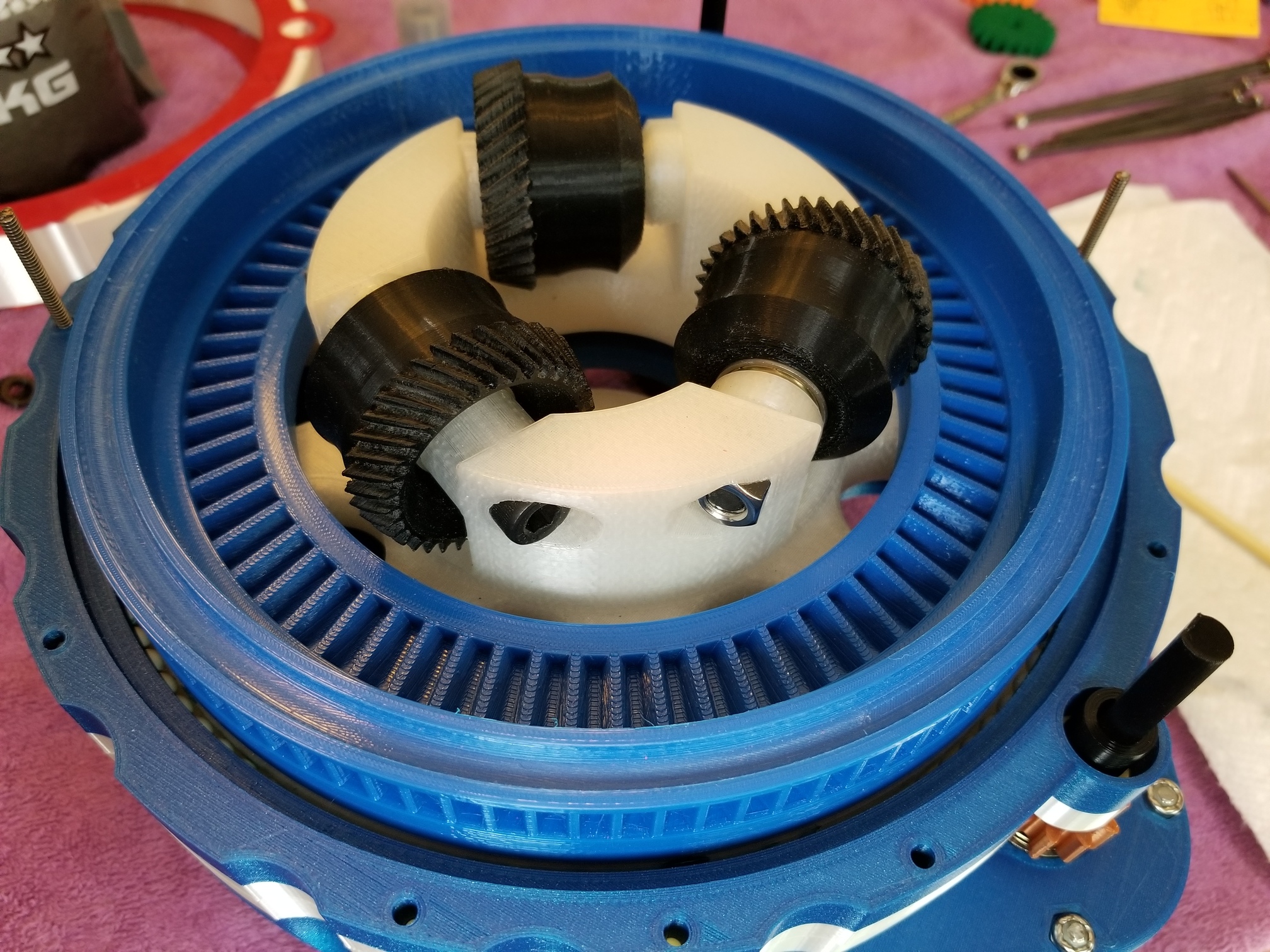
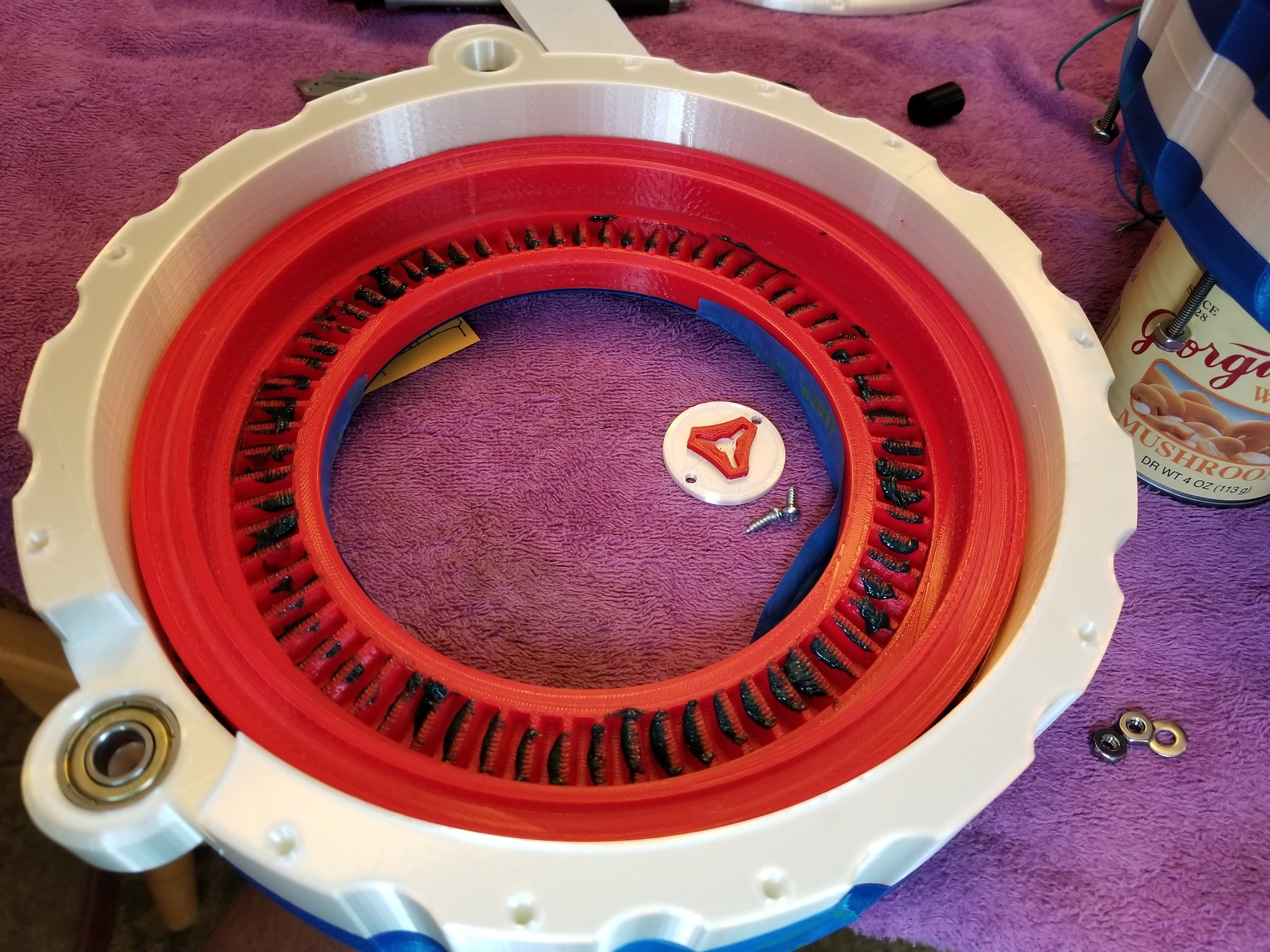
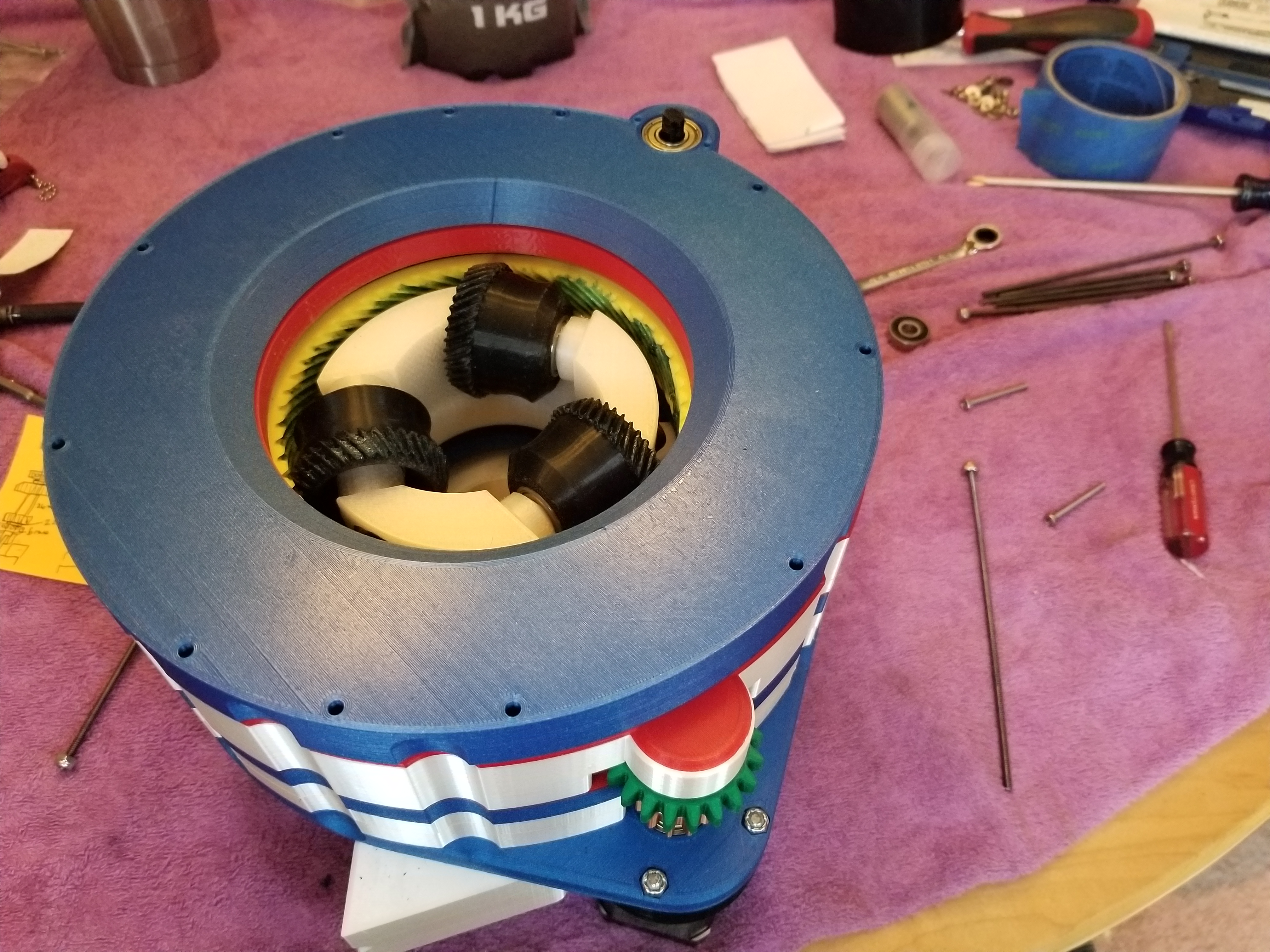
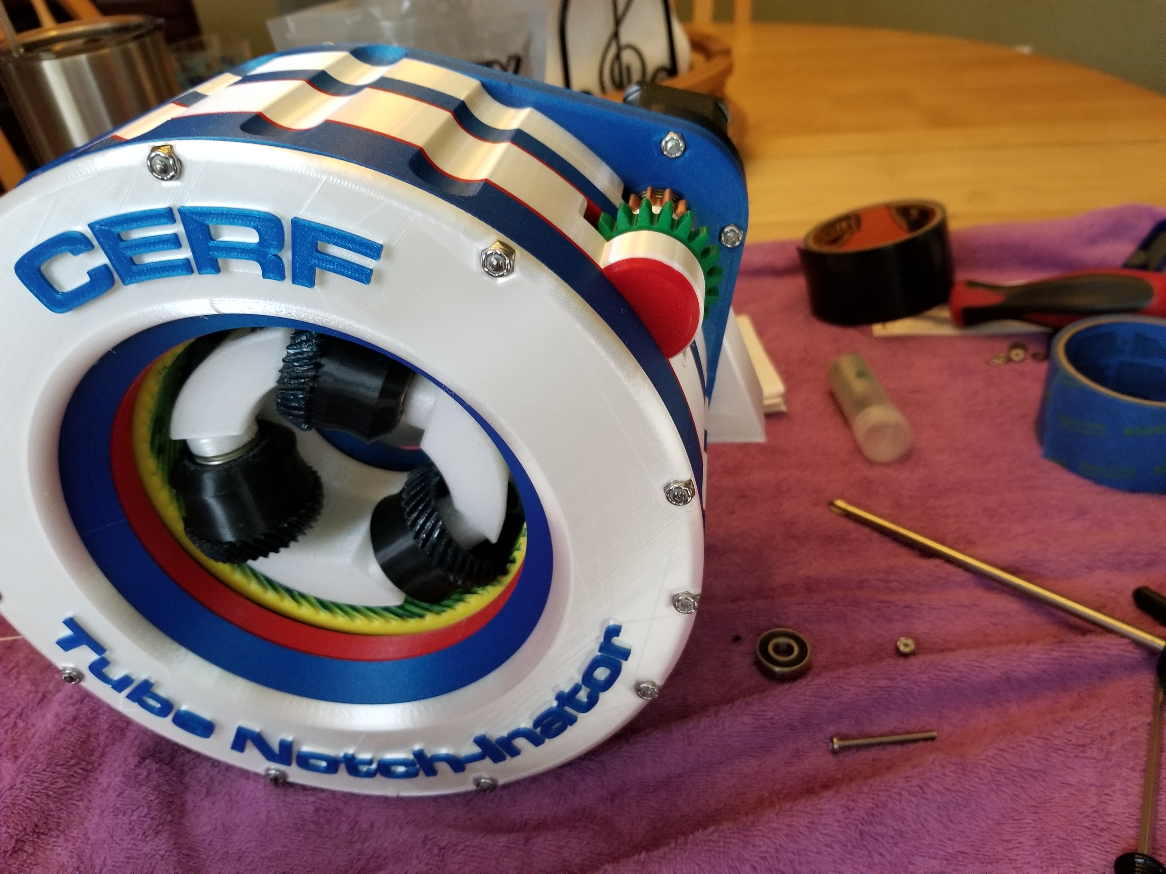
The basic mechanism here is three wheels which grip the tube. I have those wheels anchored to a boss. There are two 608 bearings inside each of the (pink in the images) rollers.
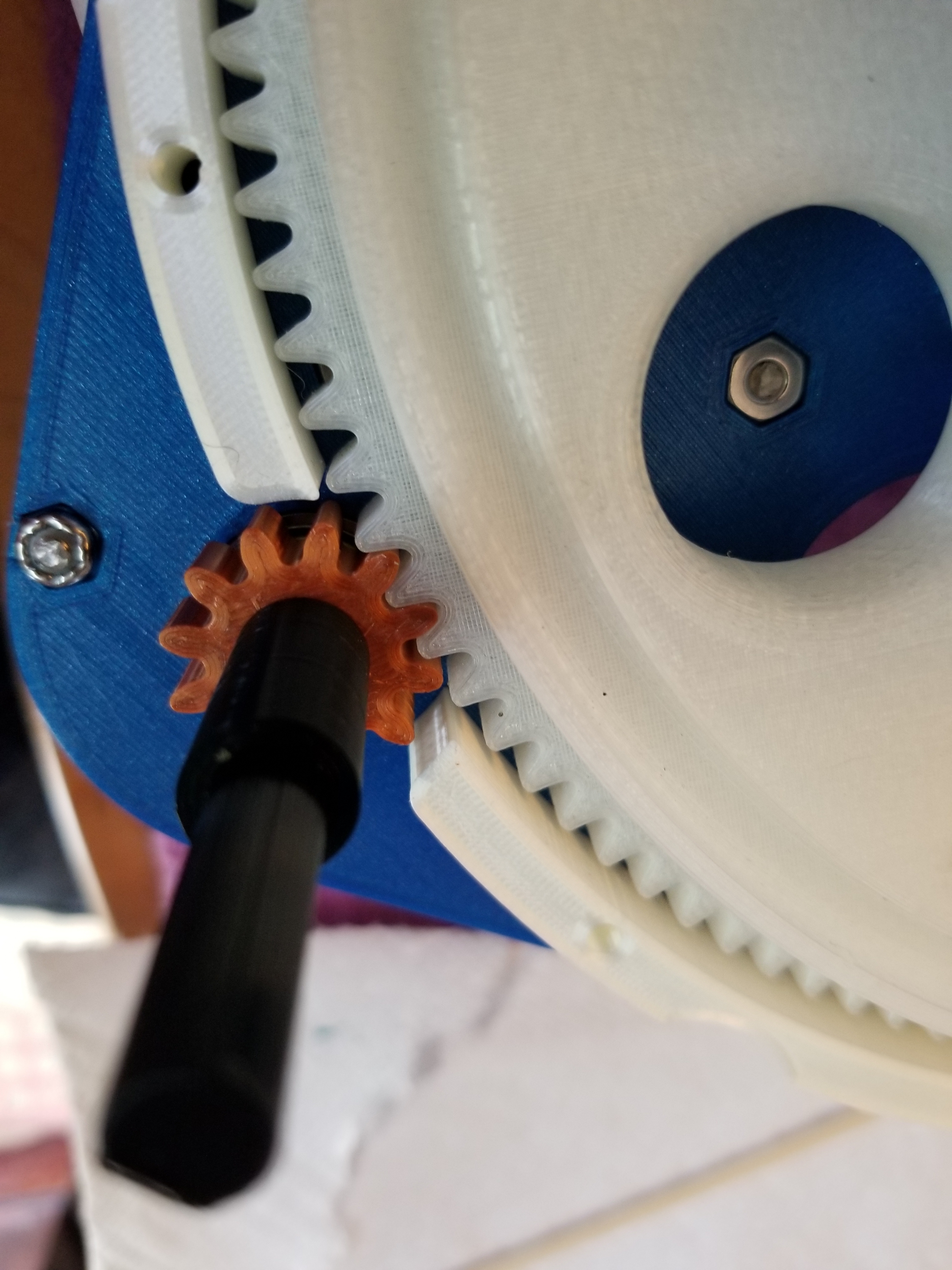
So the concept early on was that the large boss would be driven with an X stepper motor, which would rotate the whole shebang, including the gripper wheels. That would rotate the tube because the gripper wheels were holding it, natch. Feeding the tube in and out became the real issue for me. The Y stepper rotates a ring surrounding the pink gripper wheels, that is basically an inside-out worm gear. I am terrible with engineering stuff and making the gear teeth was really hard for me. Anyway, to feed the tube in and out, you just rotate the yellow worm ring and it will turn the pink gripper wheels.
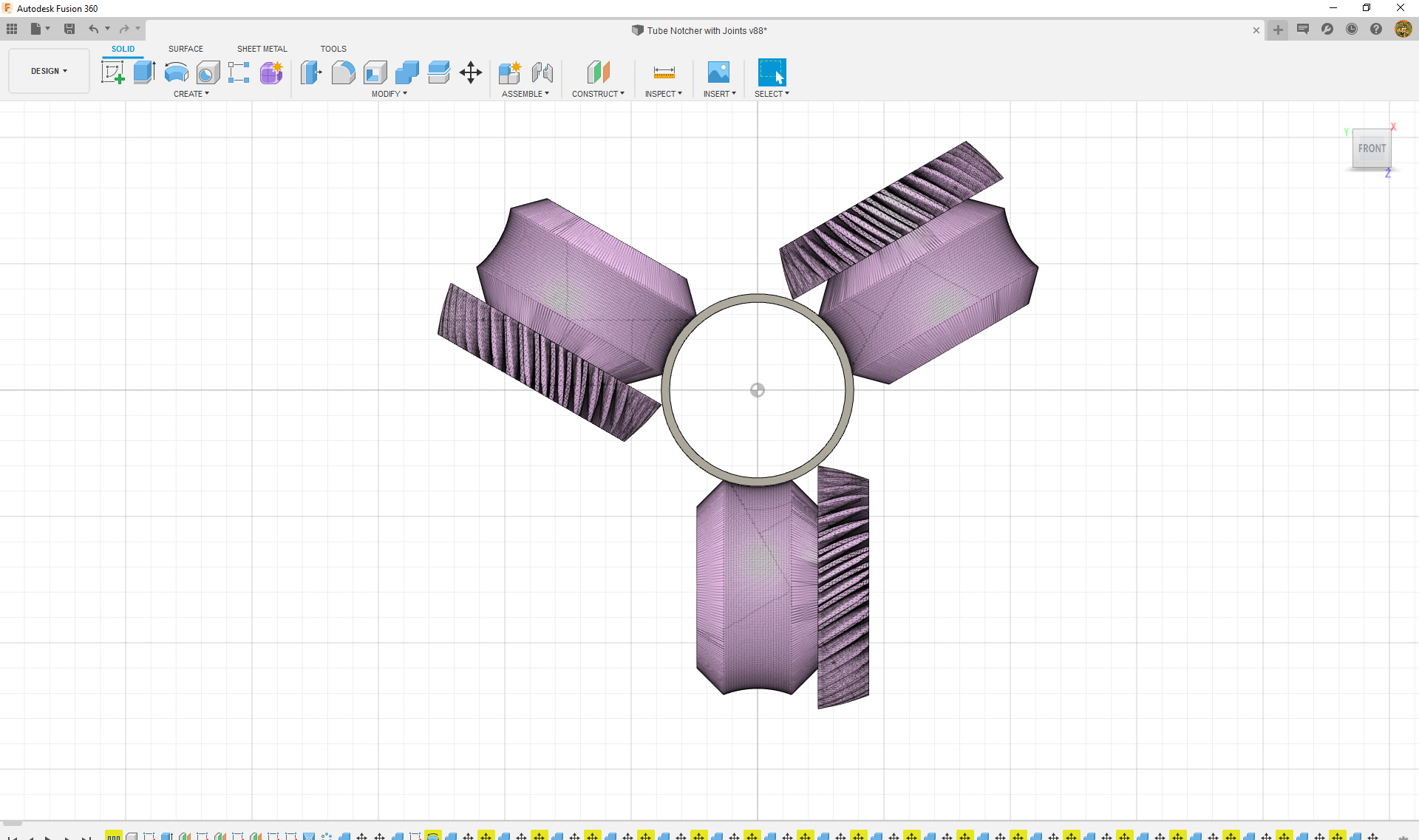
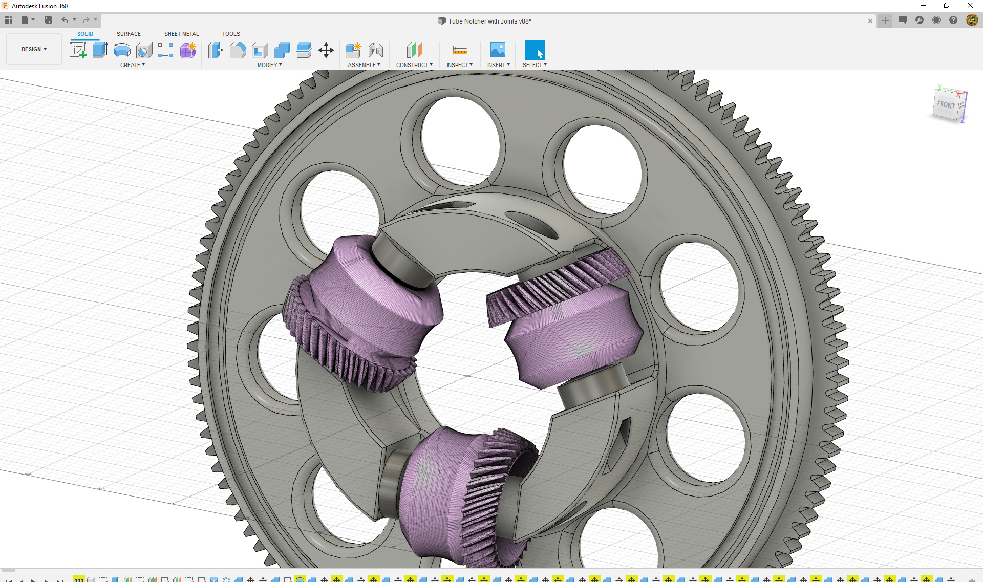
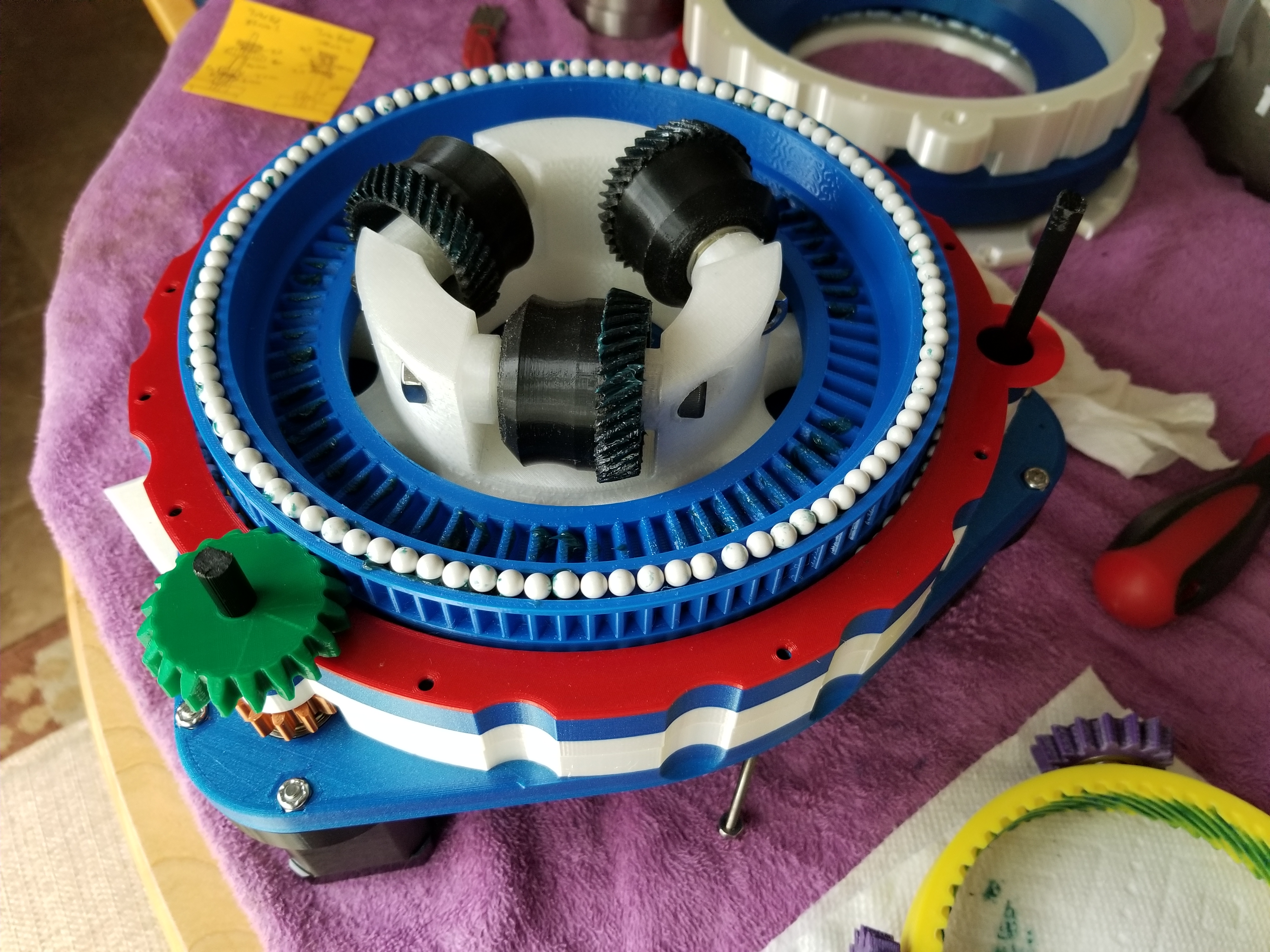
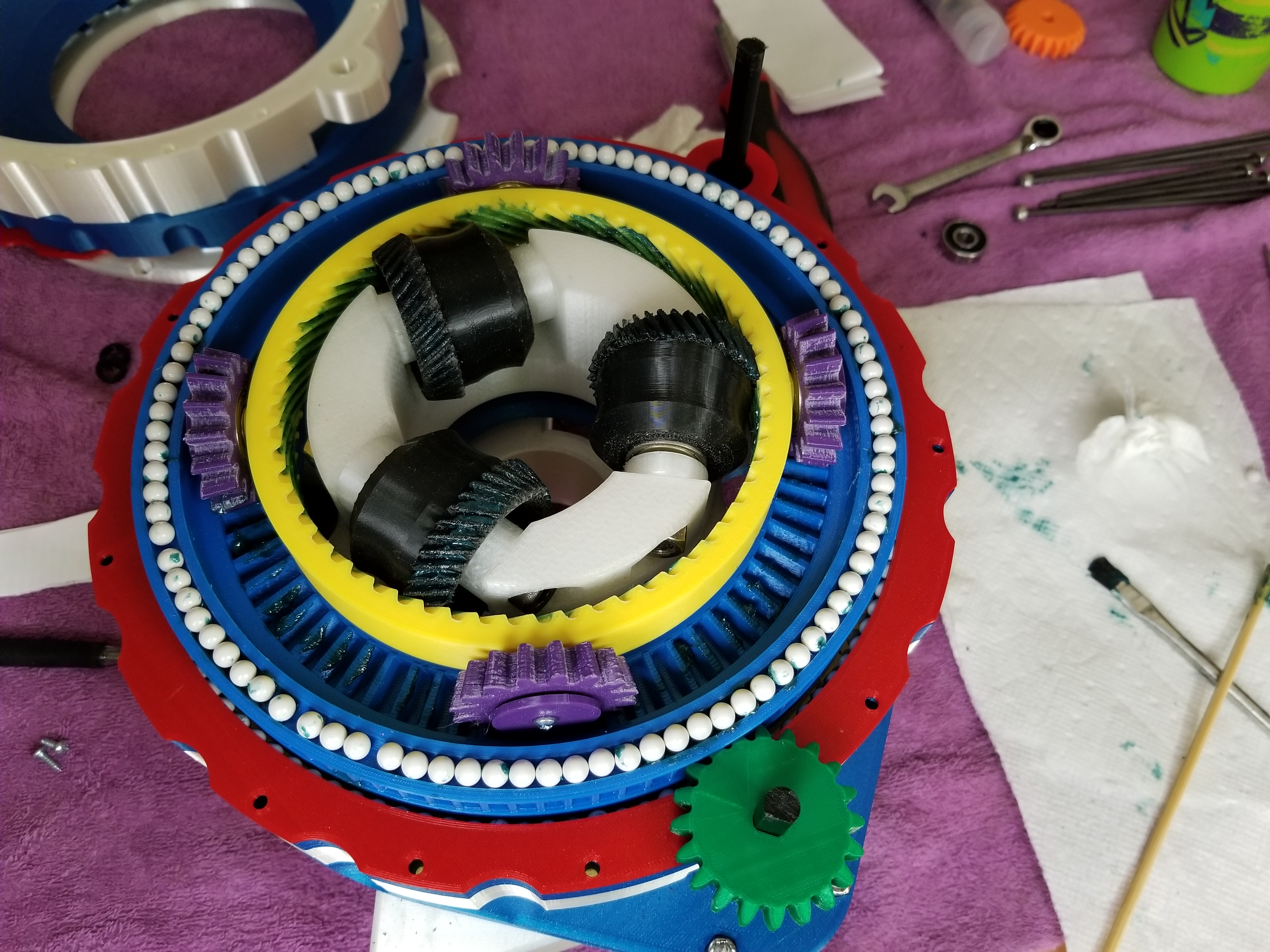
I realized this wasn’t as simple as all that, because if the yellow worm ring is held stationary, then when the boss rotates the tube, it will also drag the gripper wheels around the inside of the worm ring, so any time the tube rotates, it will also feed one way or the other. So to avoid that, I have differential gears (in purple) that attach to the yellow worm gear. Those differential gears are acted upon by one or two different ring gears at the same time. It’s a little weird but it was all I could think of at the time.
The red ring gear in the picture above is actually what I call the “compensation” ring. It is turned in the same direction as the carrier boss, but at twice the rate. So, it effectively keeps the yellow worm gear fixed WRT the pink gripper wheels, when the boss rotates. I set up the motion links in Fusion to try it out and make sure everything worked. I’ll post those motion analyses as GIFs.
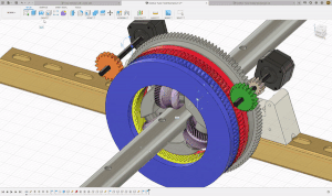
It seemed like it would work, although I was worried about gear lash and slop, especially with all printed gears. This GIF shows how it works driving the boss/compensation rotation drive shaft.
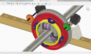
Then I reconfigured the model and drove the tube feed stepper drive shaft. It shows the worm ring driving the tube gripper wheels. I left the front drive ring on in the first video, and removed it in the second for clarity.
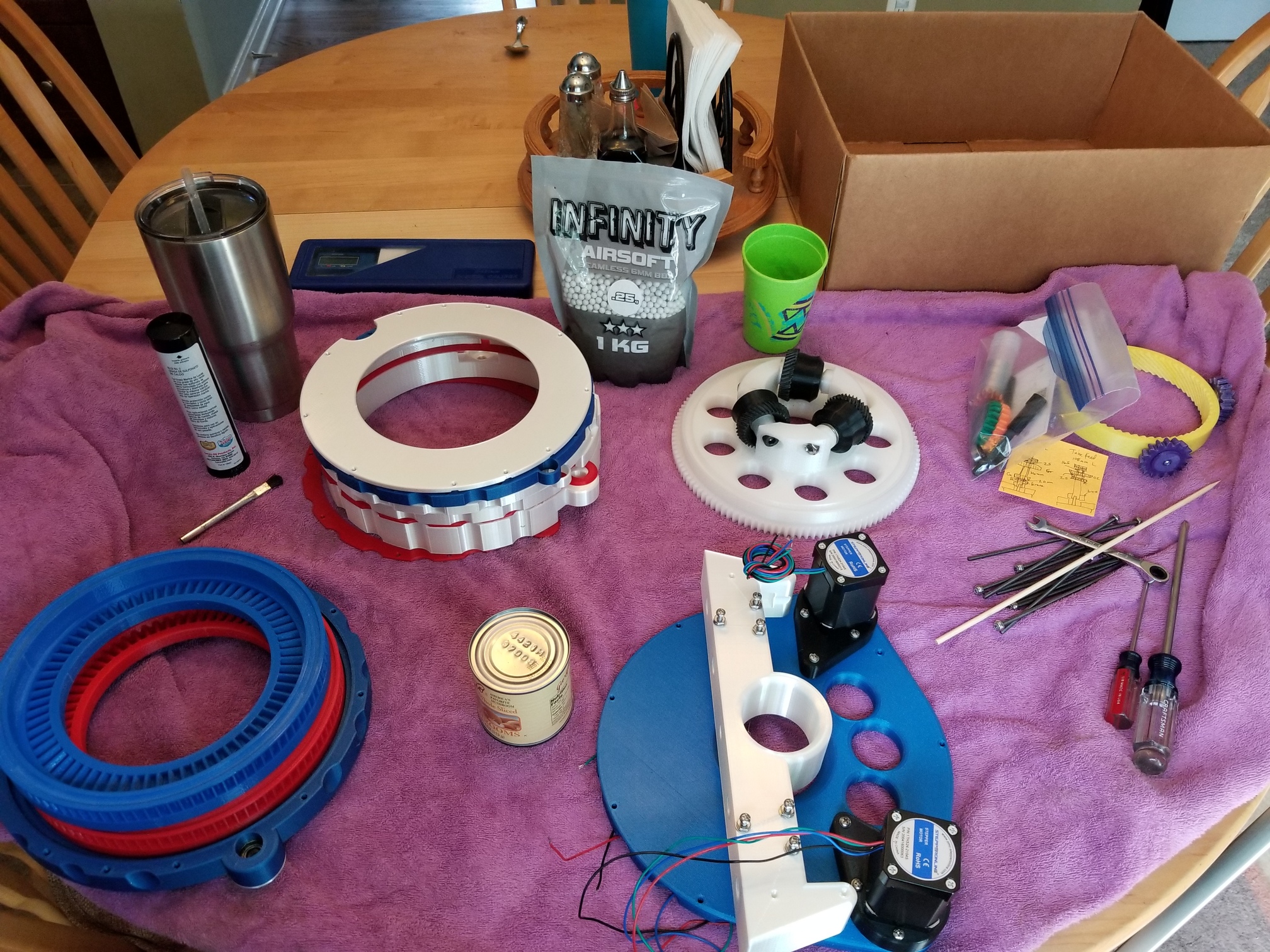
The housing parts were designed to stack, creating races and support for the radial bearing BBs. Then the compensation drive ring was fitted over the gripper wheels.
This is really slick! Can’t wait to see it in operation. How are you controlling the two steppers and synchronizing with your LR? Are you creating your own code? Also do you have any tensioning mechanisms to prevent the tube from spinning during machining or are you just relying on the compression of the rollers?
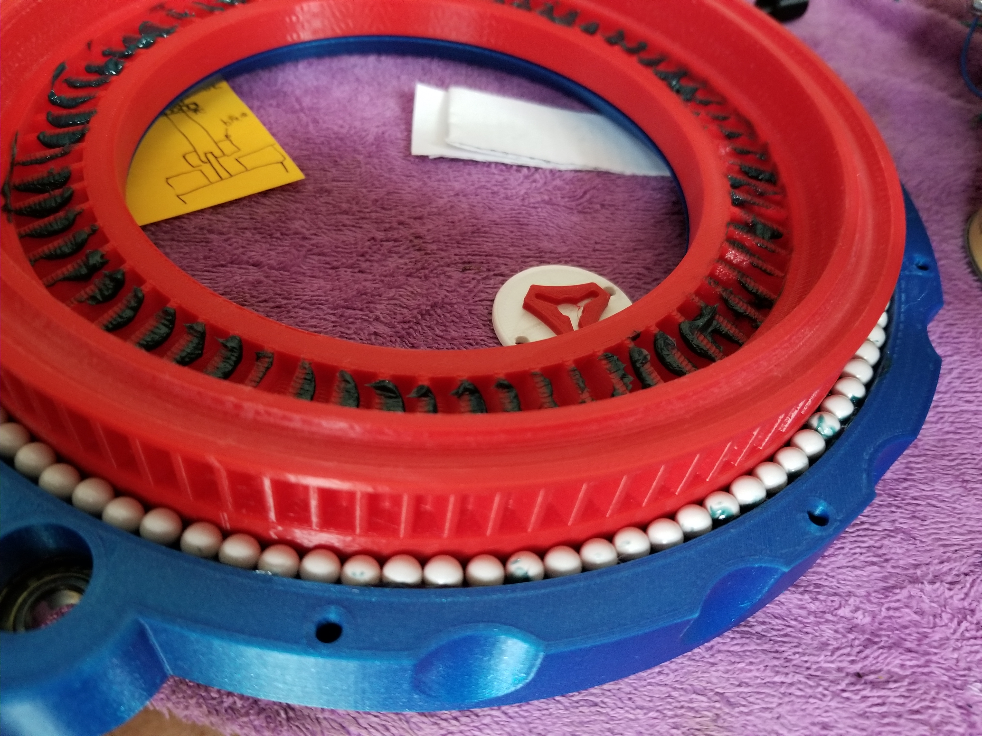
The top had to be built upside-down and taped together to keep all the bearings in place. Once the whole thing is screwed together the BBs are trapped.
While strictly speaking this isn’t Ryan’s design, it is 100% inspired by V1 and is intended to work in the ecosystem of his LR2, so I added a V1 logo, hopefully he won’t mind. This will all be part of the LR2 system in the shop. Uh, eventually.