I’m pretty stumped on this one when trying to move the axis on XY or Z I only get a Buzzing sound (working on how to link the video)
That of may have screwed up the wiring but since this is happening on the z axis I’m not really quite sure what to do. I’ve tried spending the connectors around.
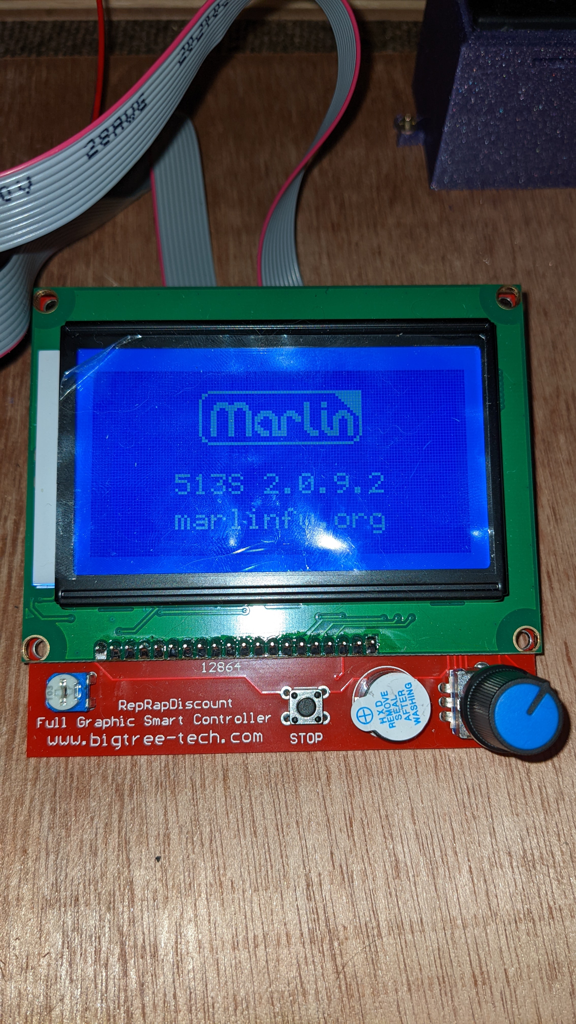
I’m using the Rambo 1.4 board with the 513s 2.0.9.2 firmware.
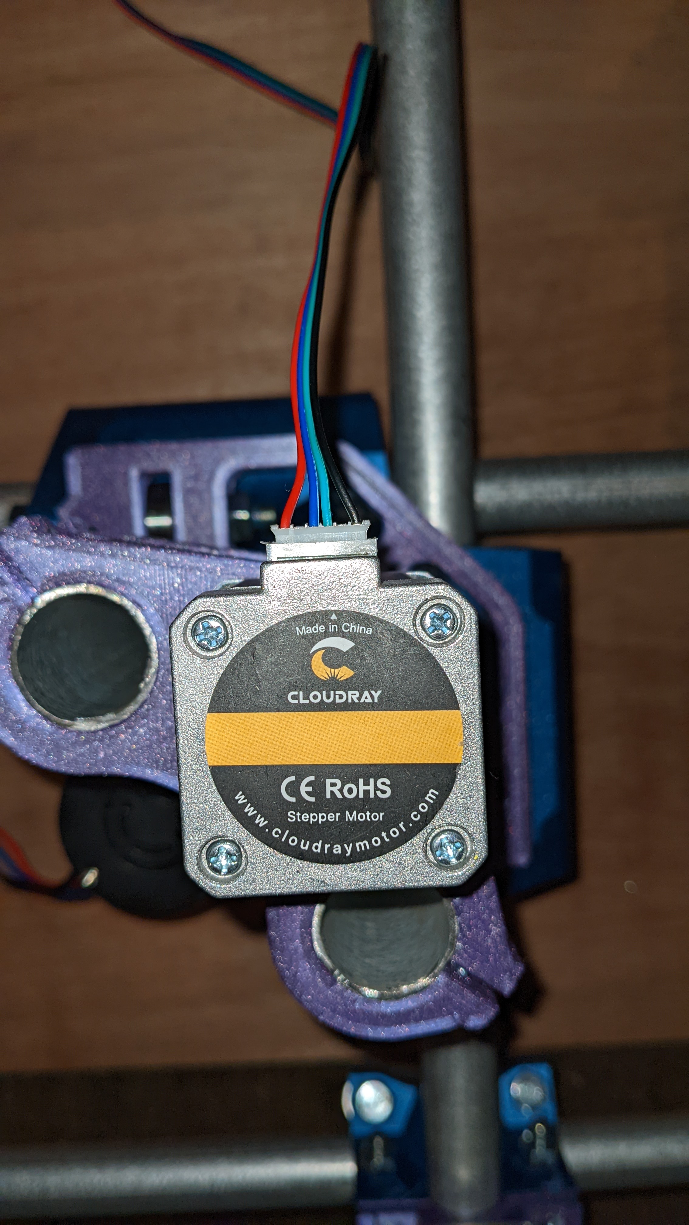
The stepper motor are Cloudray Nema 17 Stepper Motor 42Ncm 1.7A 2 Phase 40mm Stepper Motor 4-lead. They have 6 pints but came pre wired with 4 (Picture)
Steppers from different manufactures have different pin out, in most steppers the pair should be blue/green, red/black.
Can you post a picture of the wire connector at the board?
Could not quite see the wire connector but looks like all the cables are in line with the motor, try to switch the position of the blue and green wire in the connector the problem should go away.
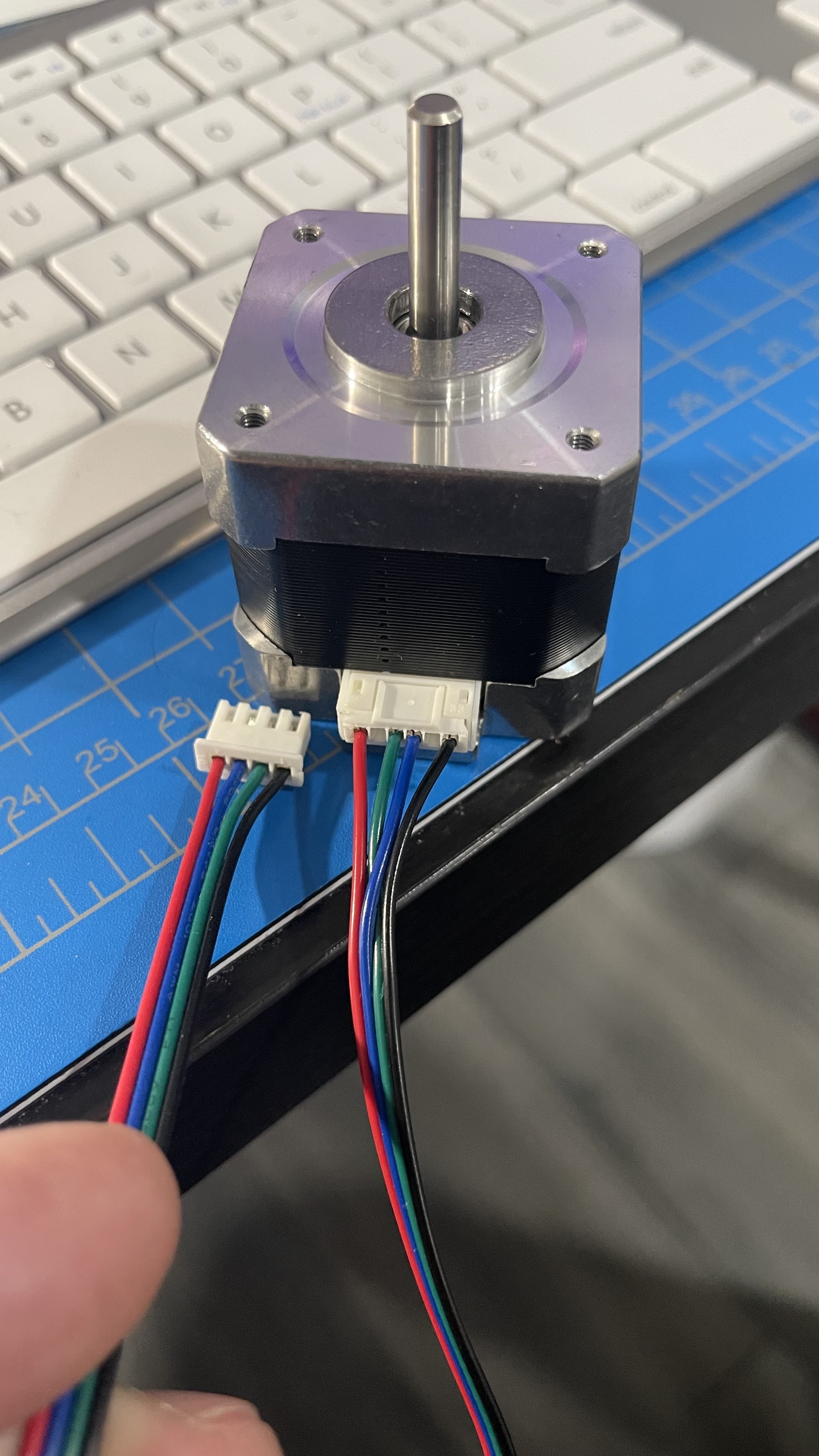
This is a picture of a small stepper that I use on my Primo for anything that only need to hold the Z in place, like laser, pen and drag knife, that does not need lot of torque or no torque at all.
Look at the 2 ends of the cable and notice that the blue and red are switched.
Thanks for your reply. So I switched the wires and it worked for the Z access. Thanks so much!
When I did it for the x and Y though, I got motion but it was rough and there was a wine sound that didn’t sound good. Will I need to rewire the motors as the wiring in series won’t match
As an alternate solution, you could wire each stepper to its own stepper driver and use the dual endstop firmware. You don’t have to have endstops to use the dual firmware.
(Bi-polar) Stepper motors have 2 windings that they alternate activating to generate motion. These are often arbitrarily referred to as the #1 winding (with A and B wires) and the #2 winding (also with A and B wires). The colors may not be reliable between vendors, or even in different batches from the same vendor over time. With the motor disconnected, there’s a pretty easy way to identify a pair of wires that make up a winding.
Turn the motor shaft by hand, then jumper or twist a pair of the wires together. If the motor gets harder to turn, that’s a winding pair. The other pair will be the other winding.
You’ll need to check your board’s documentation for how the motor connectors are wired, but most of the ones I’ve seen are 2B-2A-1A-1B, so that flipping the connector swaps the windings, thereby reversing rotation of the stepper motor.
You can do an ohm check also. Windings will have an ohm resistance that will show the 2 different windings.
man I just read that and am worried that what I wrote does not make sense.
This was really helpful and I think I have identified the way these motors are wired. I’m going to give it another go trying to wire these in series correctly this time. Probably next week when I have a bit of free time.
I’ll update everyone if I do / don’t get it working.