I’ll start things off by stating the obvious. This is well, well, into “wrong tool for the job” territory and you would be more than justified in saying explaining that “you’re better off buying the part instead”. I’ll reiterate, but more clearly this time, this project isn’t well suited for the MPCNC. That said… We’ve all been stuck at home and bored for a while so… why not? Worst case the part can be purchased and I’ve learned what not to do
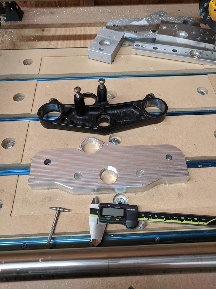
I’ve set off to make a triple tree clamp for a friend’s motorcycle. The part is roughly 260mm x 170mm x 25mm in size. Here’s what I intend to make:
We’d joked that the part didn’t look that hard to make. My bluff was called and a piece of 1" 6061 plate was dropped off the garage the next day. I took plenty of time to ensure the the machine was leveled, squared, trammed, legs dropped to the lowest level possible, spoil board surfaced, etc to give myself a fighting chance. If this is to work at all then all of those things need to be spot on. The 6061 plate was rough sawed to size and the work was held down with cap screws + t-nuts.
The rough cut stock was modeled in fusion so that I didn’t waste quite as much time cutting air. I wasn’t happy with the estimated cut time and got more aggressive with cut. I suspect that the steps visible in the perimeter of the part are from tool deflection. They’re uniformly facing away from the part with the bottom of the endmill pushed out further than the top.
Fortunately I’d left stock all of the way around sufficient to be cleaned up with a finishing pass.The camera exaggerates the steps, I swear! Things turned out about as well as I could have hoped up to this point with every dimension that I could measure being within 0.2mm.
I chose to use a 1/4" single flute cutter for the entire job. In theory I would have gotten better cuts by shortening up the machine and using cutters with less stick out but I’m not confident enough in my fixtures/indicating to do so. I was worried that I’d end up with lips half way between the part. Not great for clamping! The 1/4" endmill has held up like a champ for the tool paths that have been used thus far.
More cutting…
Chamers and spot drills marked out with a 90* vbit.
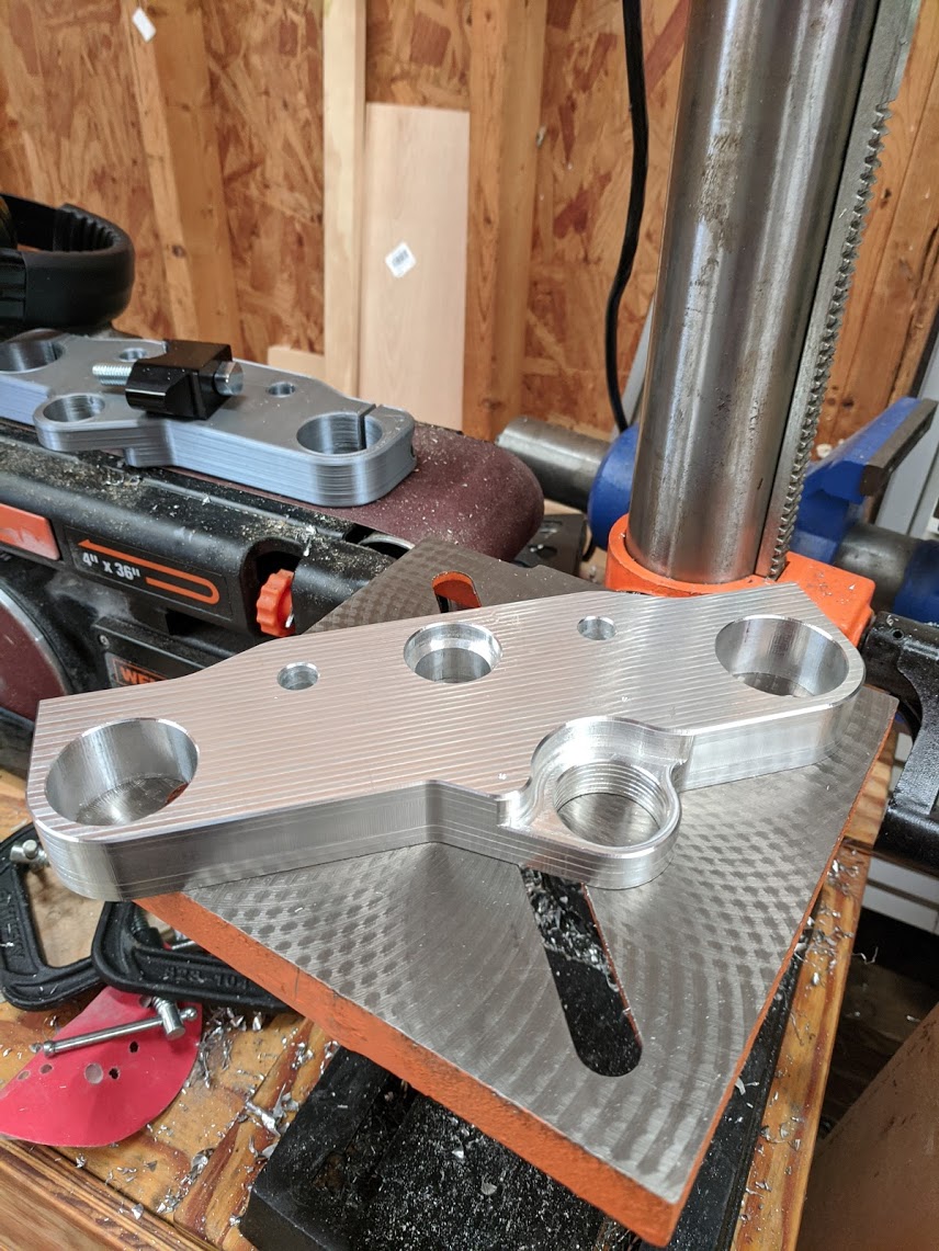
Drill press is much better at plunges than my router.
Where I’m leaving it for now:
I’m doing my best not to scrap the part by taking test cuts on scrap and templating out my cutting parameters in fusion before applying them to the real work piece. This just might work.
I’m a little jealous. (A lot, really). Many years ago I had designed a new heel guide for my motorcycle. My plan was to prototype on my bike and then possibly sell the parts to the small group I was a part of. It was more expensive ($150 for a single set) than I was willing to pay at the time. I wish I had this set up back then. Could have cut them myself, saved money on the prototype, and then made money selling them. Keep up the good work with the perfect tool for the job.
Sorry if I gave the wrong impression. The MPCNC is certainly capable of cutting the part if you’re patient and have an appropriately sized/tuned build.
In that same vein, I’ve been fighting tool deflection for some of the more critical bores. I’ve attempted to remedy this by toying with climb cutting, conventional cutting, finish pass tolerances, and different tool paths. 2d contour finish passes(stepped or full depth) always deflected enough to leave small steps in the bores. What I ended up settling on were 2d adaptive paths to clear the majority of the bore and then coming back in with a helical bore toolpath to bring the part to size. The helical bore toolpath with a shallow pitch never loads up the tool like adaptive paths so there is much less deflection. Couple that with being a helix and not a stepped toolpath and the end result is closer to what’s needed for this part. Note that the bore toolpath may way out the tip of your tool more quickly than using comparable contour toolpaths.
There’s still deflection happening but it’s something that I can account for in cam. I found that my parts come out roughly .2mm under sized (for bores) and .2mm over sized for outside profiles. I suspect that the the tool uniformly deflects away about 0.1mm away from the cut.
I also noticed that the tool deflects more near the bottom of cuts than it does at the top but that’s to be expected. Longer levers, etc. This is the reason the forum recommends keeping machine legs short and raising the work piece up as close to the cutter as possible. This is also why there aren’t any step marks near the top of the part but they’re visible at the bottom. The bottom of the tool is deflecting away from the part which forces the top of the tool back into the part.
So, is it the wrong tool? Maybe not. But you’re certainly going to have to do your homework to get the results you want
You’d get less deflection if you swapped in a thicker mill for the finish pass? Also an extra finish pass helps. That is a very thick piece of aluminum though !
Already using this 1/4" cutter from our friend drillman1. I tried a dozen or so different combinations of finishing pass depths and widths, 1 and 2 flute cutters, and climb/conventional tool paths with little difference in results.
The helical bore tool paths that I settled on are able to keep things close enough. The test cuts for the steer tube in my last post fit with little/no wiggle room.
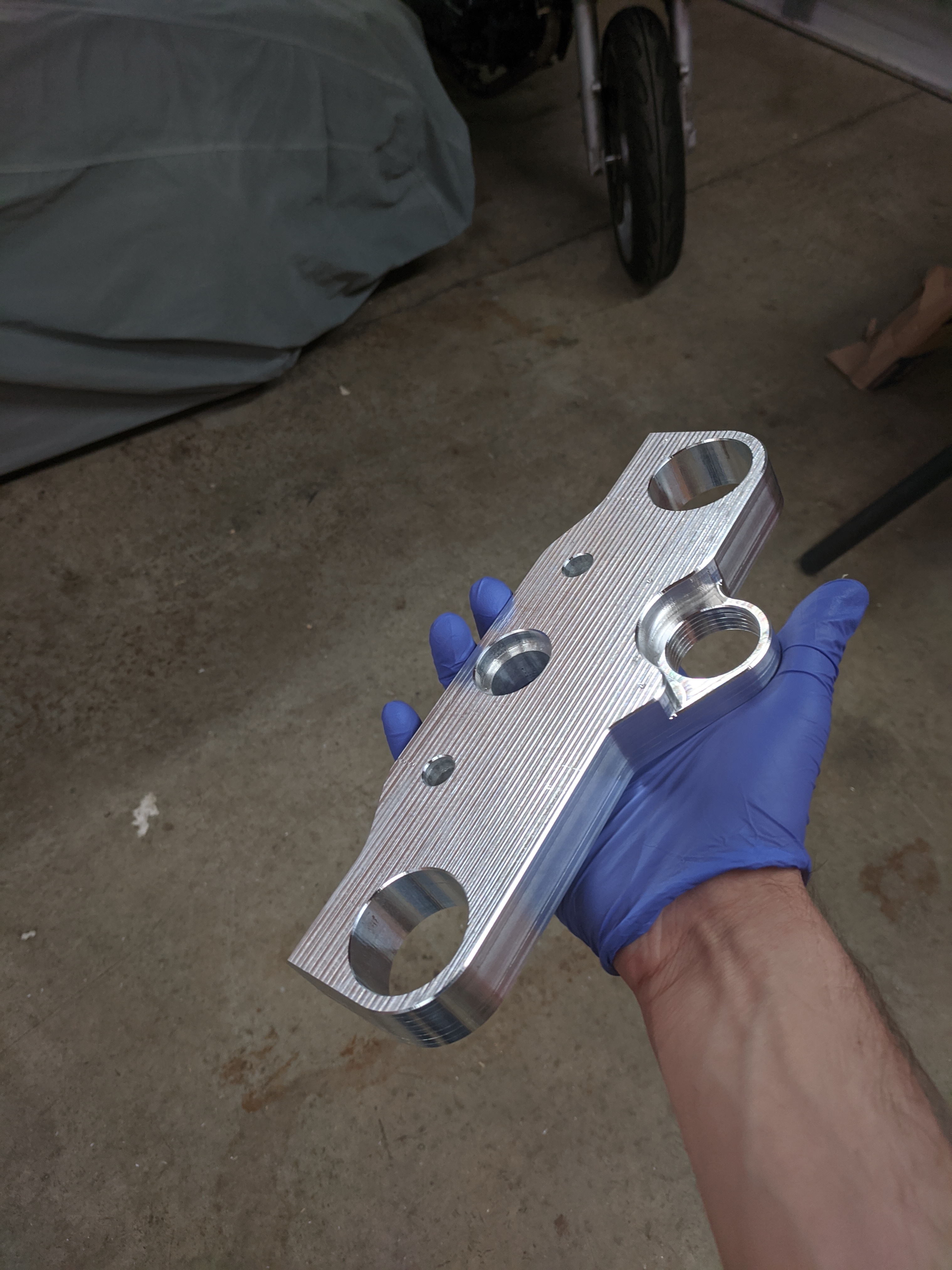
Sure do. I took a set of snap gauges to the steer tube bore. Old part came in at 25.04mm. Bore in the new part measures 25.09mm. I’ll take it! Definitely a bit of trial and error in making test cuts to get to that point but it seems to work well enough. Cutting parameters had to be adjusted to be larger in cam to compensate but it worked out.
Heh, yeah. I’ll be honest, I’m not sure what types of tolerances are acceptable on these sorts of things. I’ve been measuring off of the two spare clamps that a friend has. Both spares are “lightly tap with a mallet onto the forks/stem” tight so I’m trying to mimic that as closely as possible.
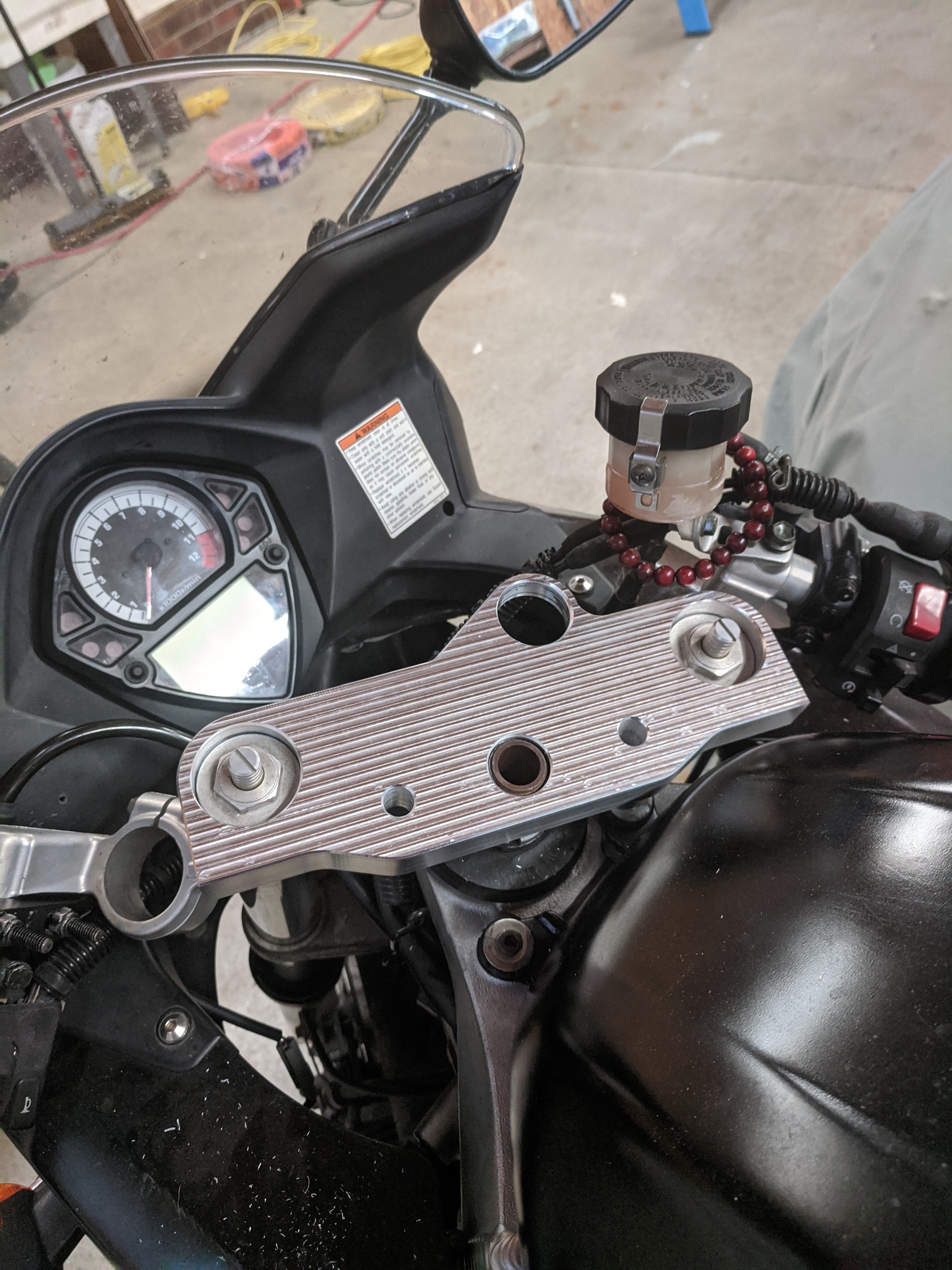
Just about done with all of the cnc work! Just need to face / chamfer the opposite side. Planning on slitting the clamps with a band saw and using the drill press for the remaining holes.
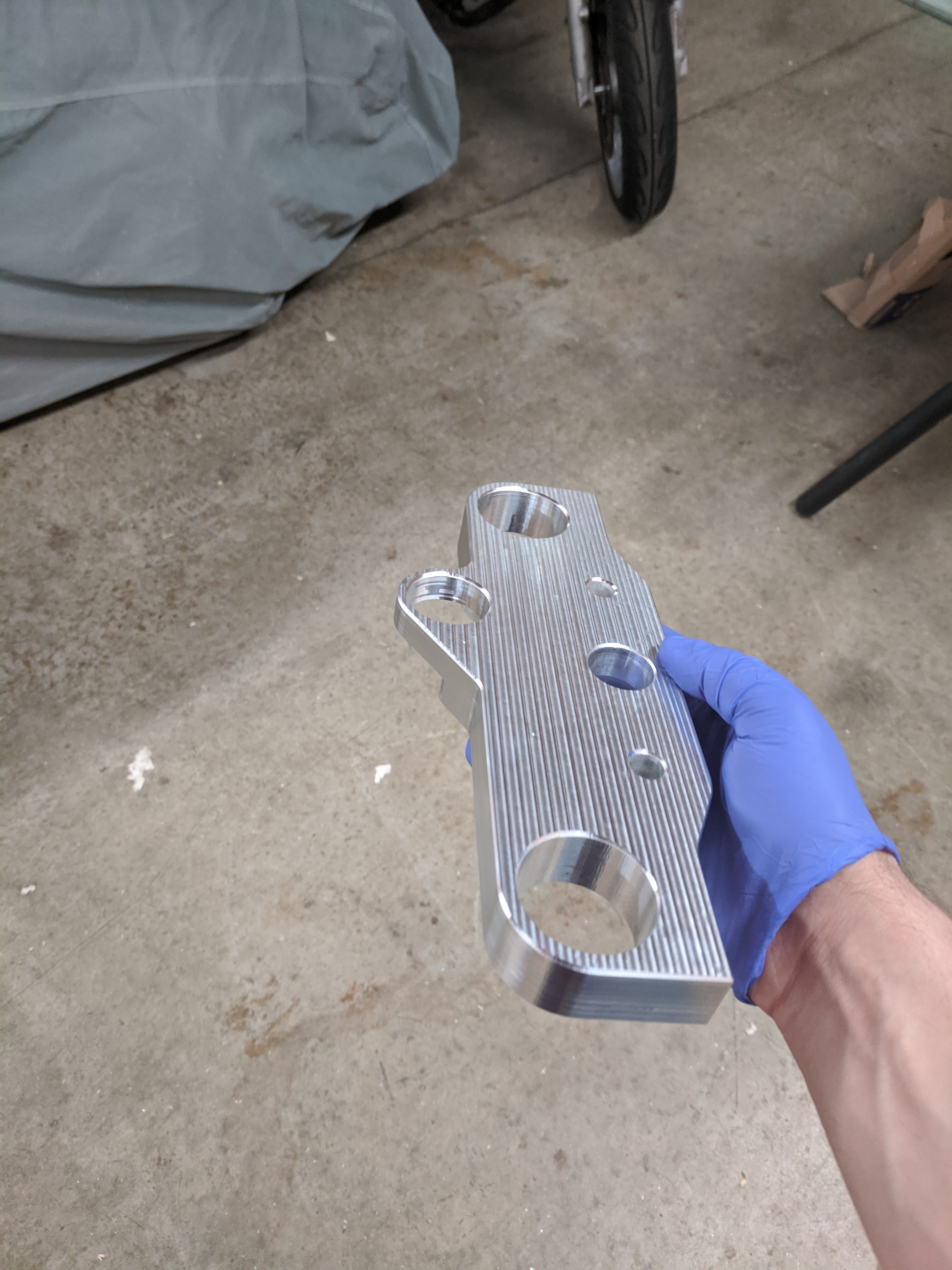
I’m no mechanical engineer but this thing is considerably beefier than the cast aluminum part that it was modeled after so I’m hoping there is no true crash test!
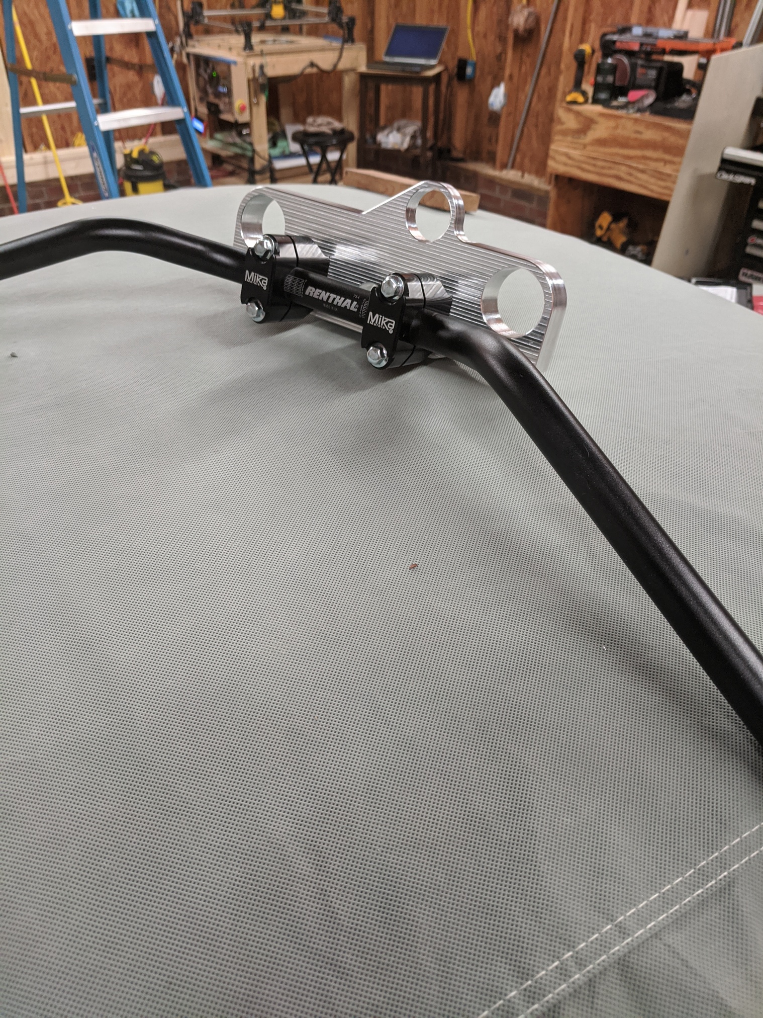
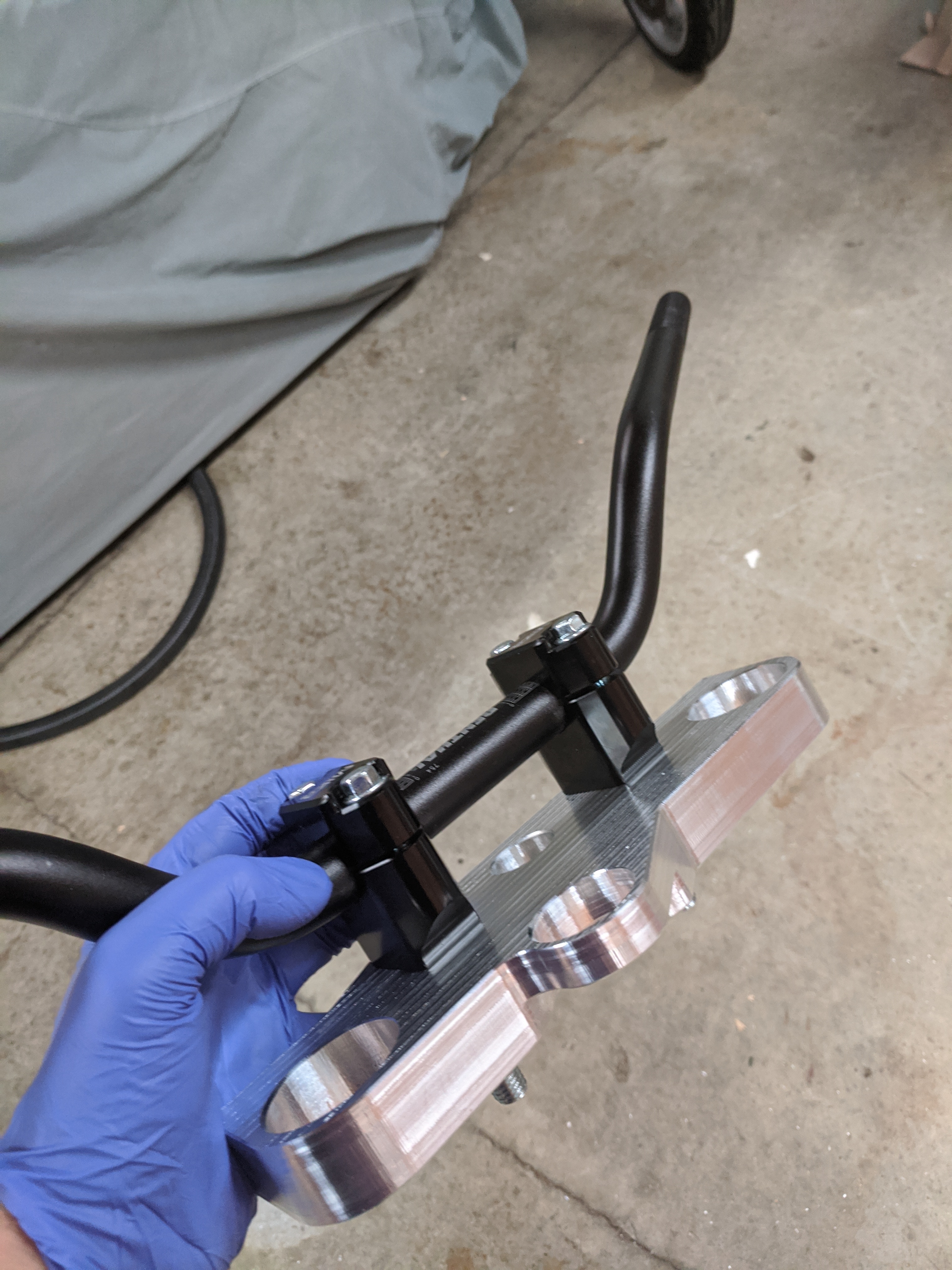
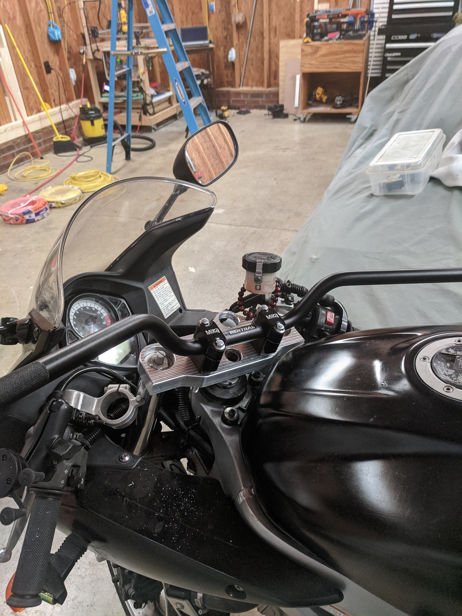
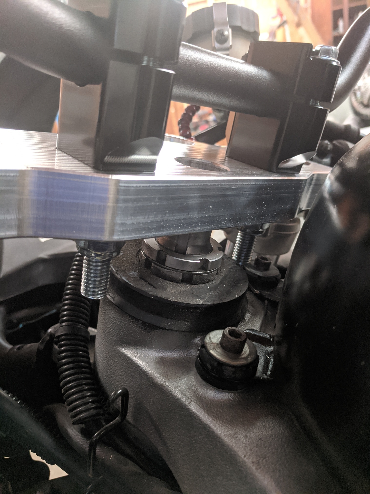
Some more progress. I should only have manual work left at this point unless I need to recess the bar mount nuts and cut down the bolts. Last picture should explain.
Very nice! I always loved billet motorcycle parts. When BiMota first started selling chassis kits loaded with billet parts in the US, maybe '70s sometime?, there was an accessory store in South Orange NJ that sold them. I used to regularly leave nose prints on their showroom window.


 The helical bore tool paths that I settled on are able to keep things close enough. The test cuts for the steer tube in my last post fit with little/no wiggle room.