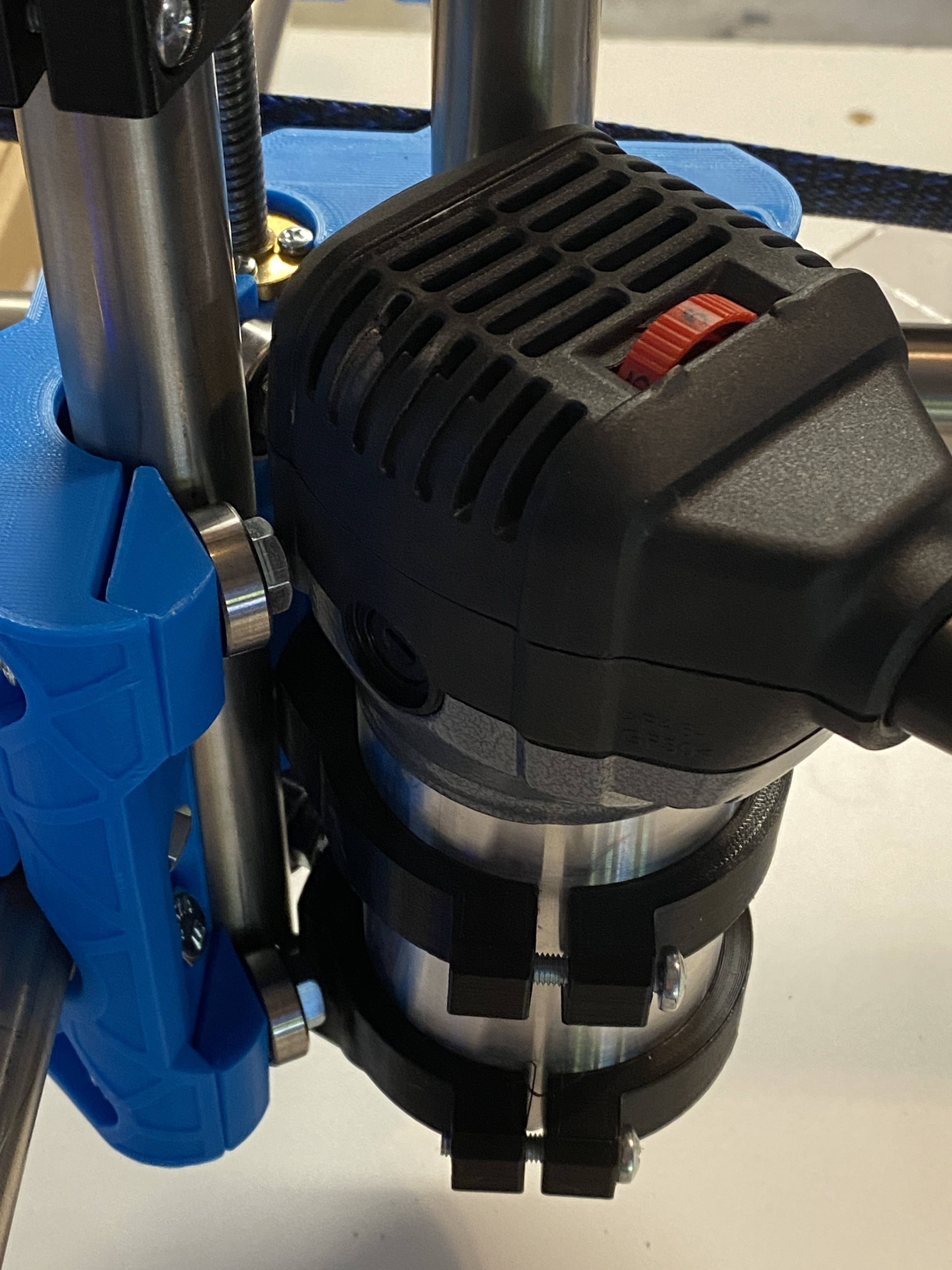
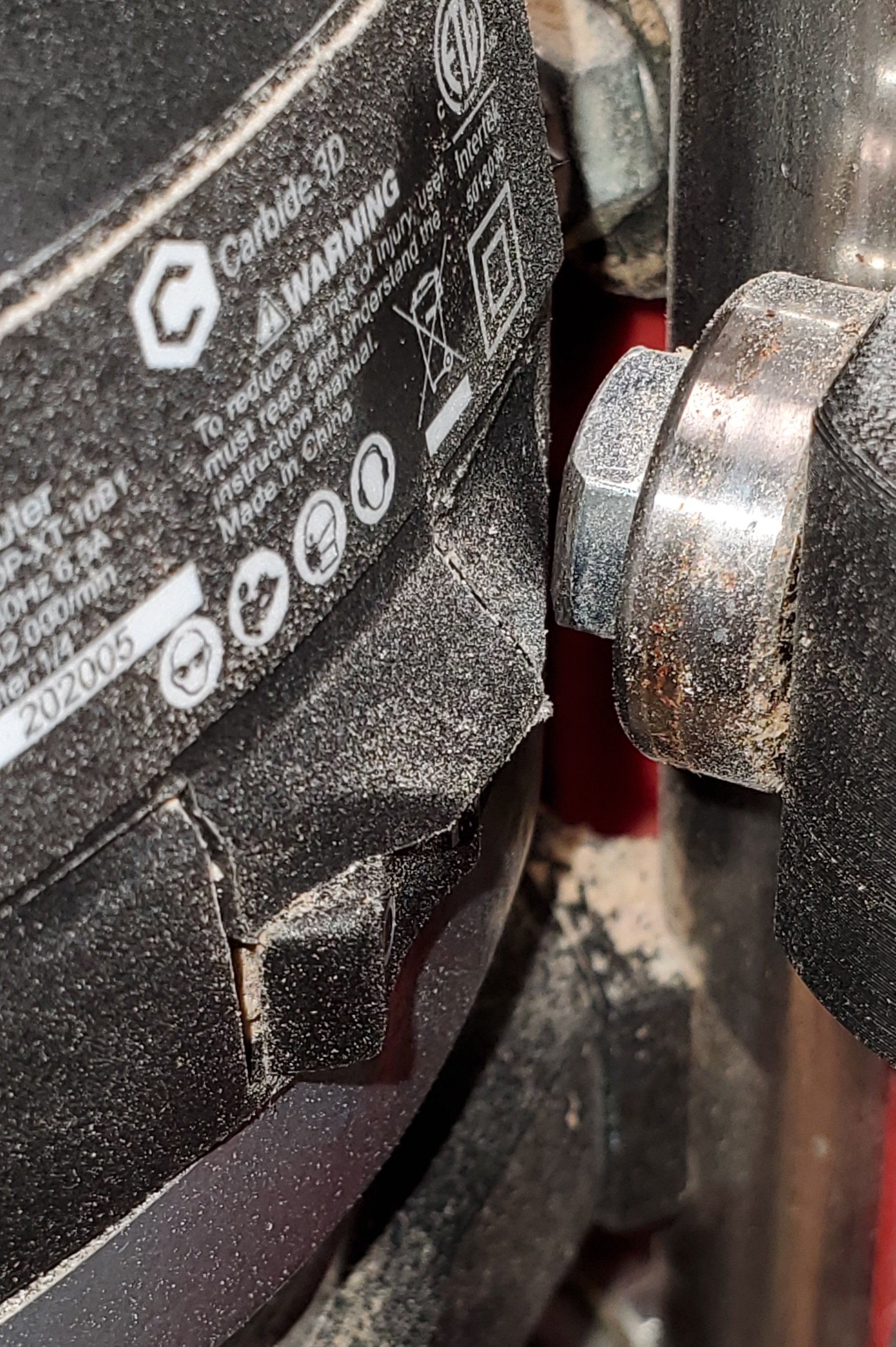
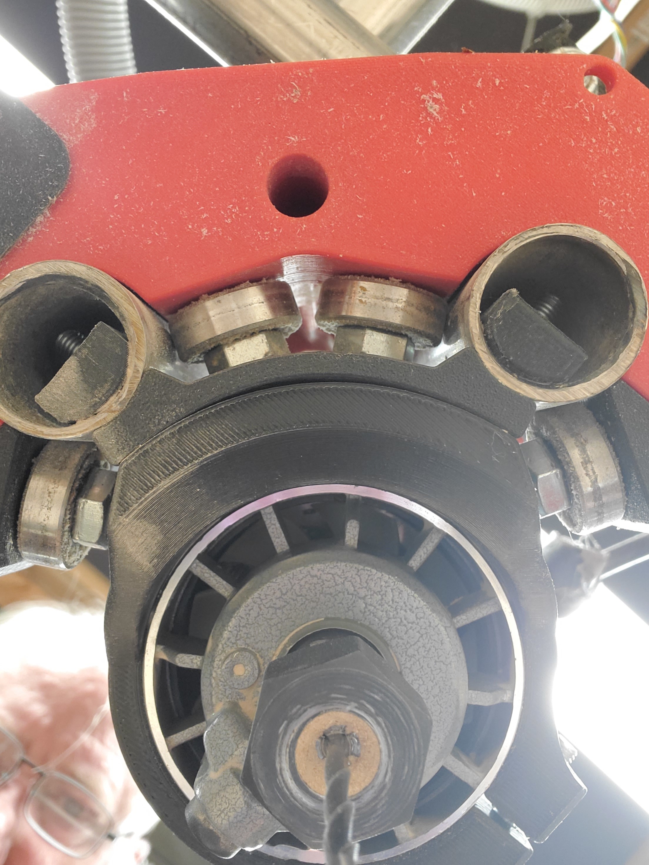
I read somewhere on the forums that the Carbide 3D was identical to the Makita but with free collets. It turns out its not the same especially with regard to sizing of the top as it can’t pass up and down past the core adjustments bolts. See pic.
(1) Tweak the mount to add a small amount of space. Assuming @Ryan would be willing to share the STEP file.
(2) Try an unofficial mount.
(3) Return/Sell the router and get the Makita
I have the Carbide 3D router, and there is a rotation using the Makita mounts where the router just clears the bolts I used on my machine. I’m not at home to take a picture of that rotation. I’ve thought about modifying the mount to add a couple of mm more clearance. I’ve already reworked both brackets to make them a bit stronger since I have twice snapped them doing something stupid.
In the Blank Mounts section of the MPCNC Primo tool mount GitHub page, Ryan provides the Makita Tool mount in STEP format which is a major step up (pun intended) from reengineering the mount from an STL file. If you want, I’ll be glad do an (untested) remodel of these brackets with a bit more standoff. It will likely be a day or two before I can do the task.
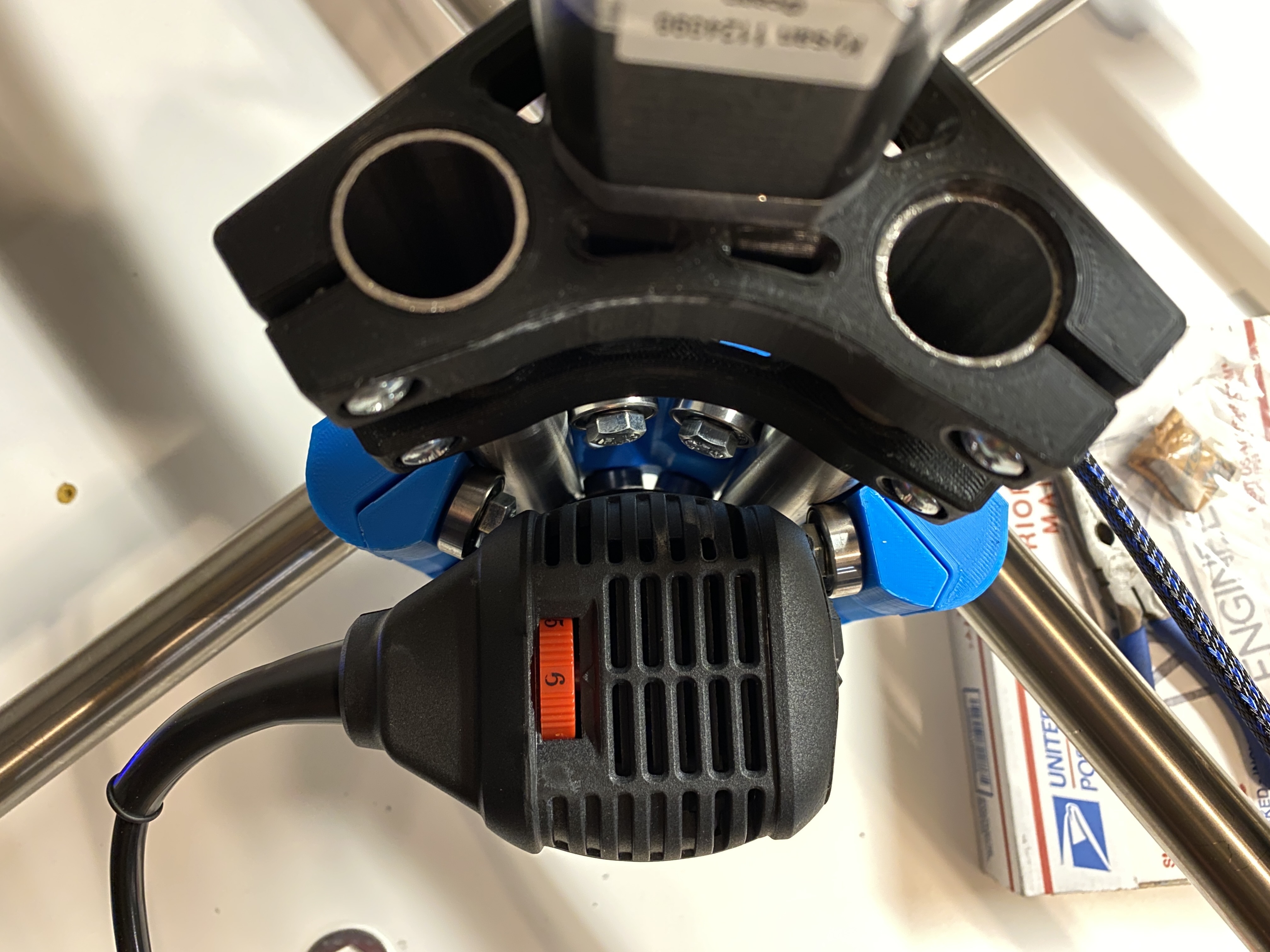
I’ll provide both the rotation and a modified mount, but it will likely be Thursday before I’m home and can do the tasks. I believe the lock button on my router faces out and is aligned with the Y axis.
My tolerances for my router is very tight. If the bolt head were a little bigger, or if the bolt edge was not vertical, it would not clear, but currently it does clear. The router is aligned so that the lock button is facing -Y on the table.
The attached ZIP file contains the reworked mount. I added 2.5mm. The geometry should be correct for mounting the router, but the finish is rougher than I like. Fusion struggled some with editing the STEP file, particularly in adding and deleting chamfers and fillets, but also on things like offsetting faces. To get something a bit more refined, I’d likely have to start from scratch. I started with the version of the mount that I’d already modified to have stronger ears.
I included the STEP file as well as the two STL files. Let me know if you need any additional changes, and I’d like feedback on whether 2.5mm is the correct amount to add.
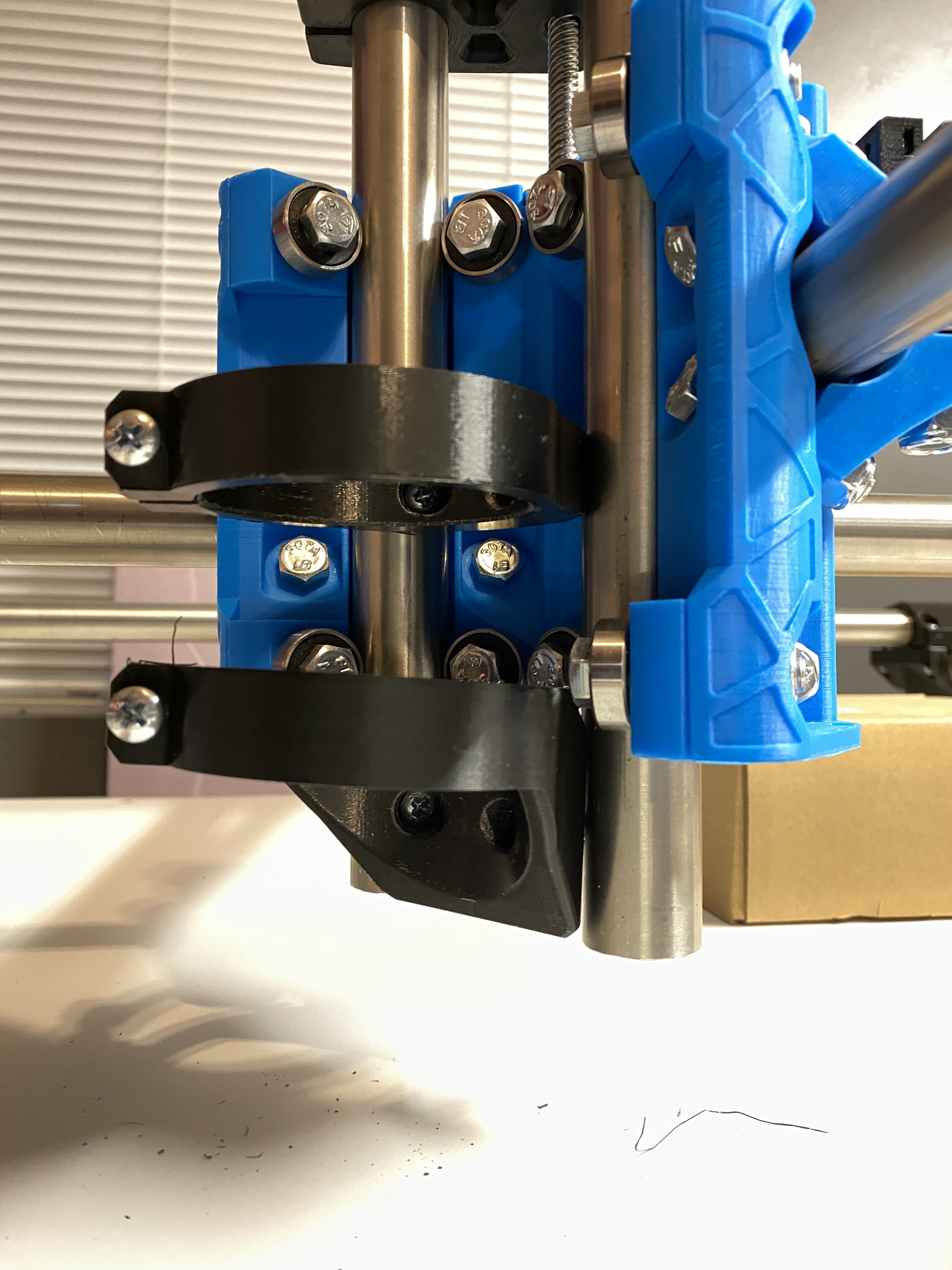
Your fit is way off. I cannot see how it is mounted from the pictures you presented. Do you have the Upper and Lower tool mount plates from the Primo package installed?
Oh man, I didn’t realize I had to use the spacets plus the tool mount. I thought something was off because my x-axis wasn’t as tight using just the mount. Now it makes sense since it will pull the rails. Thanks for your keen eye.