In the process of wiring my MPCNC I am using the Tape Measure Trick to manage the cables. Though, I wasn’t happy with just attaching the cabling to the MPCNC with zap straps. Instead I’ve designed these two mounting arms to help. I’ve prototyped both and they work well. Going to wait until I’ve finished the wiring before putting them in Thingiverse, just in case there are more modifications.
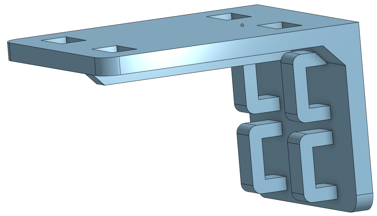
The first is similar to some other mounts I’ve seen - it attaches to the stepper motor with two zap straps through the arches on the vertical tab. The cabling then attaches with zap straps to the top.
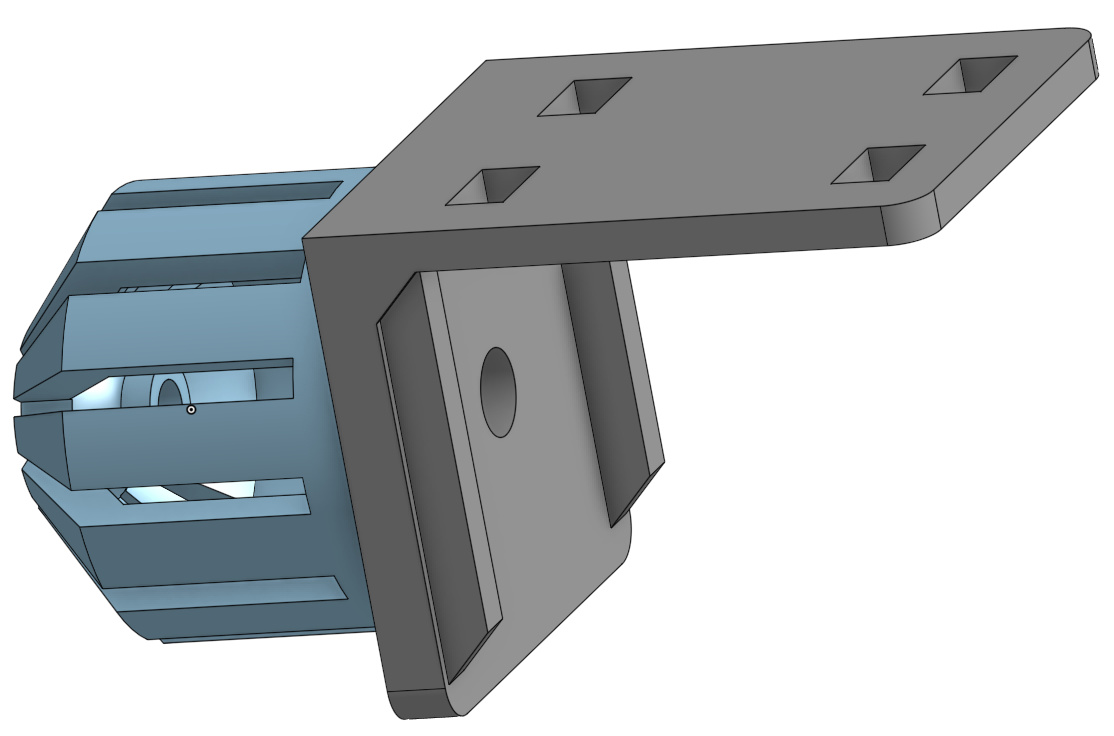
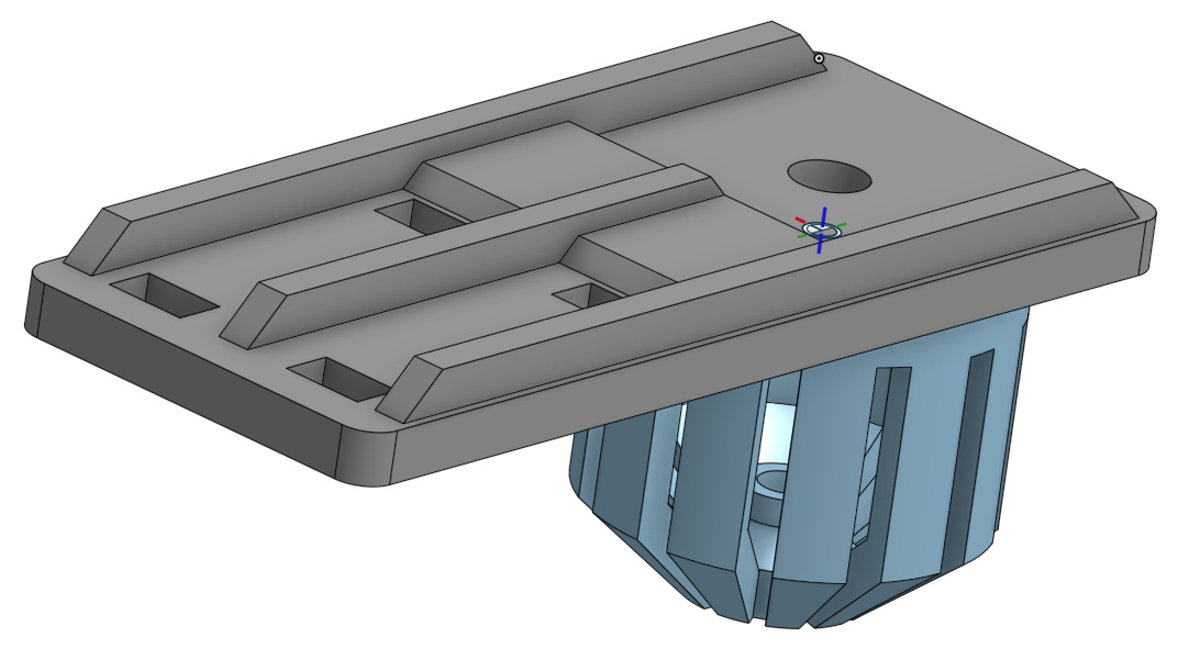
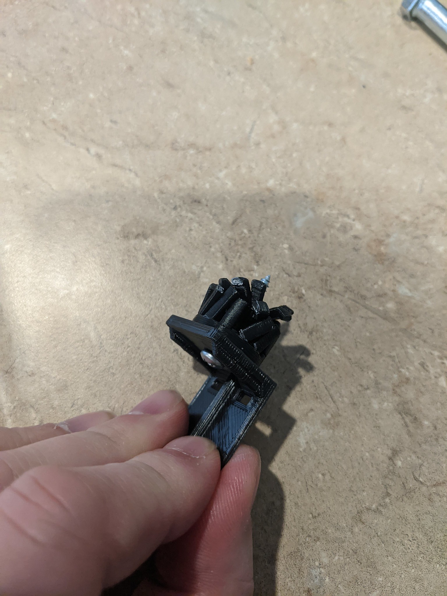
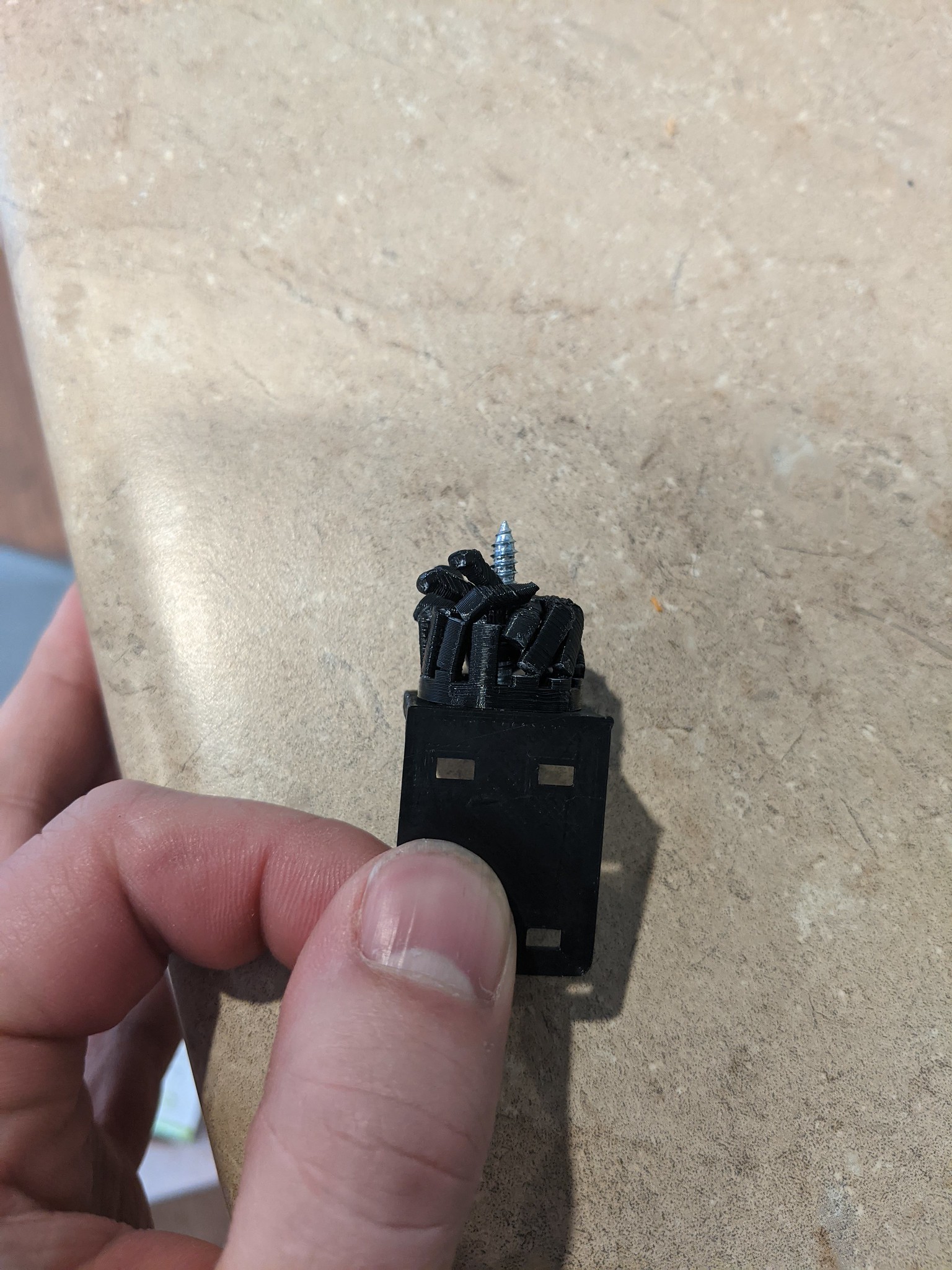
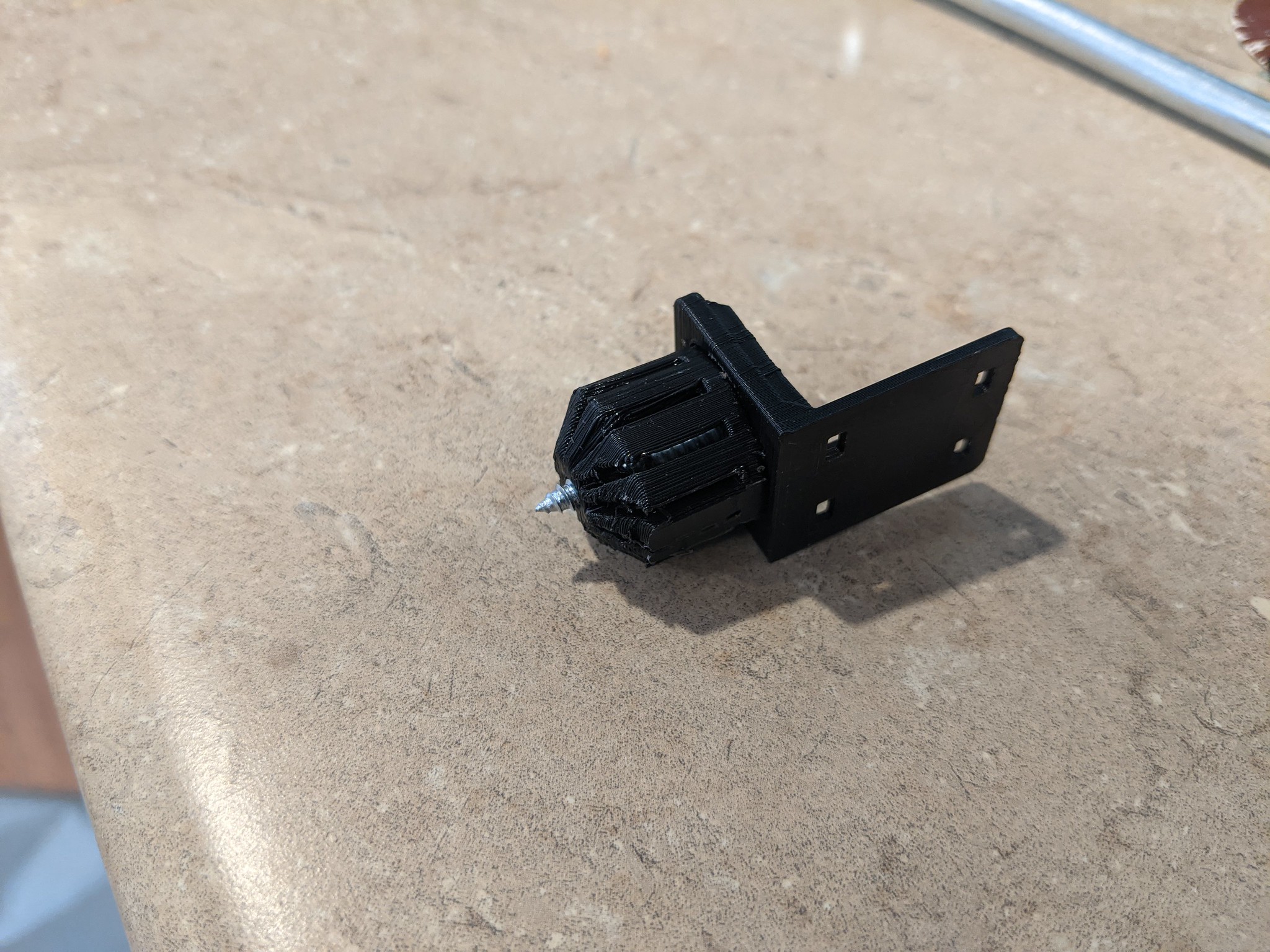
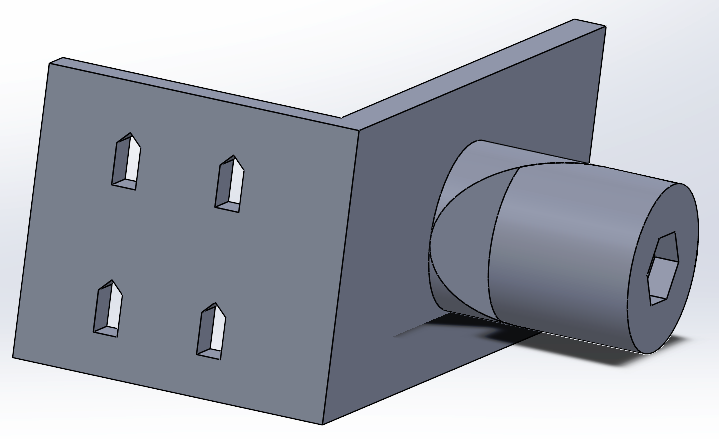
The second mount lets you manage the cable by exploiting the MPCNC’s pipe. I think this is a new idea as it uses an screw and a basket. The basket expands as the screw is tightened to create a force fit within the MPCNC tubes. The basket and the mounting arm are held in alignment with each other by 4 pins on the basket and holes on the mounting arm.
I’ll likely create 3rd version that uses a horizontal mounting arm and the expanding basket to be use on the Z-axis.
I use a similar method for my drag chains. In my case it’s a simple split plug. Easy to print and quite secure once you wedge it with a #10 sheet metal screw. I left a channel in the bottom for the wire harnesses that go through the tubes. Not as fancy, but they work well. I Dislike mounting things to the motors, they get hotter than I like printed plastic things to be on. Probably not an issue here unlike places where the MPCNC can get in trouble just because the ambient temp is hot.
You know that Ryan has repeatedly said to never mount anything to the top of the Z axis… this is why my mount has that tall tower on the x rail, so that I can use the provision for mounting on the core clamps…
I like your design for the basket clamp, but where there is a perfectly usable provision already in place… why not use it?
I don’t know the inside diameter (ID) of C-23.5mm pipe/tubing? It works with 1 inch/25.4 tubing which has an ID of about 22mm. I suspect that it will be too big for the C-23.5.
Let me know the ID of C-23.5 and I can see if the CAD files will update easily. If they will I will post a C version.
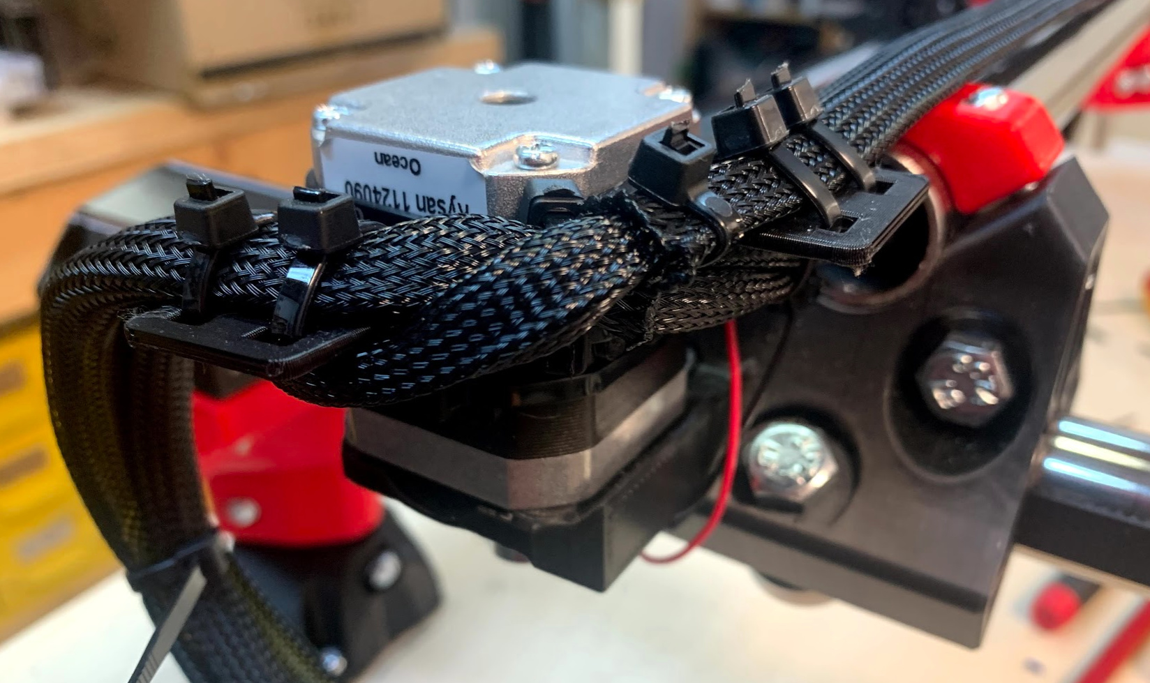
This is the z-axis tube mount. The horizontal mounting bracket attaches to the basket that goes into the tube with a screw (seen in second picture). The screw makes the basket expand and hold the mount tight.
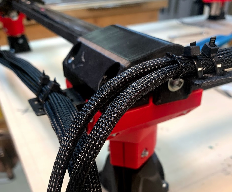
Here the wire bundle (with an embedded tape measure) start at the z-axis tube mount and then loops to the right before traveling back to the left. The z-axis wires travel slightly above the tubes (held up by the embedded tape) and are the ones seen passing over top of the truck in the 3rd picture.
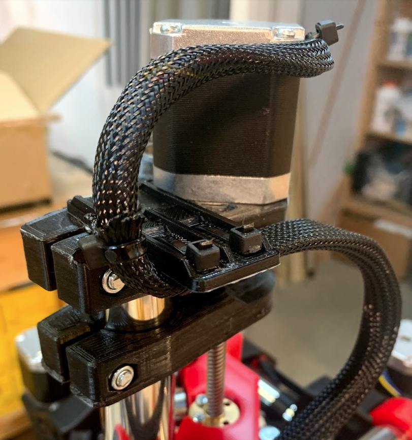
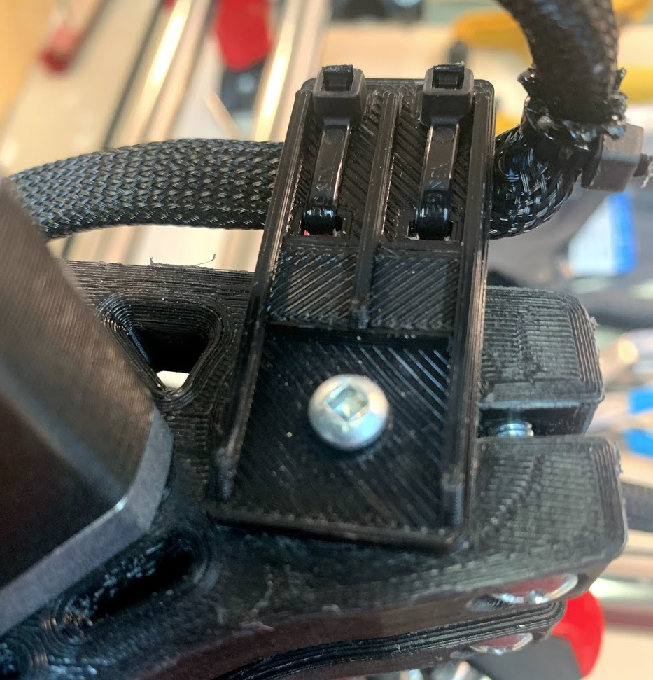
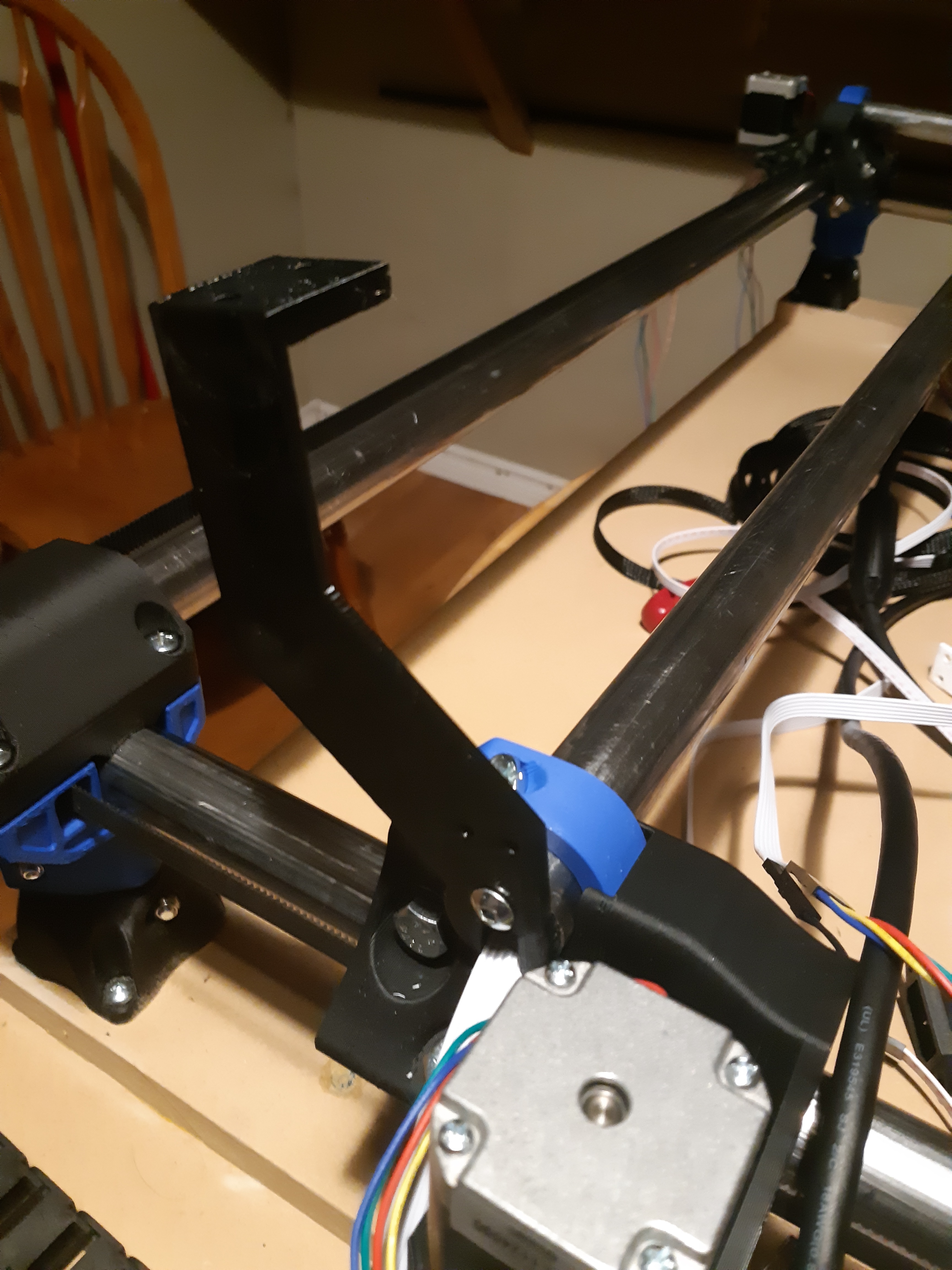
Here are two motor mounts connected to the x-axis motor.
The left mount routes the x-axis wires (with an embedded tape measure) down from the x-axis motors into a loop that heads first left then loops back to the right. The wire bundle travels along the x-axis, slightly above the table.
The right mount is terminating the z-axis wires (with an embedded tape measure stopping at the mount) so that the z-axis wires can flex back and forth (these started in the 1st and 2nd picture). This cable then continues without the embedded tape then piggy backs on top of x-axis wires (that have a tape embedded).
Finally they x-axis/z-axis bundle and the y-axis bundle (wired the same as the x-axis) arrive at the corner. X-axis/z-axis bundle is on the left and y-axis is on the right.
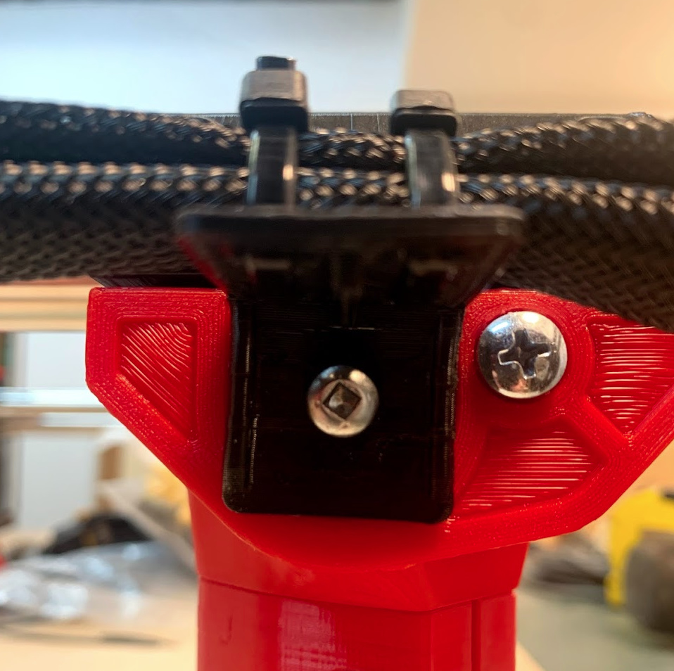
These are similar mounts as seen on the motors but they connect to the basket just like the z-axis mount. The screw expands the basket and that holds the mount firmly in place.
Could you also include some wide shots that show your entire machine so we can see which way the cables exit and better understand the orientation of everything? Thanks so much for all your work, it is a very timely post as I have a lot of loose wires that I’m going to need to manage soon
Thanks a bunch. I was going to screw the tapes down in the corner, but floating might also be a great idea. Will try to print them when I am back at home, even though I got the 25mm version. Only thing I am confused about is how it is going to print without supports.
I just queued up a print for the basket at 90% size, to check the fit on EMT. My measurements indicate that it is around 20.5mm ID for the conduit I measured.
Any chance you could post step or solidworks files? I think it would be easy to make some improvements to make them print more easily, especially to avoid flat overhangs, but it’s easier to redesign from scratch than to edit STLs.
Well, that didn’t work so well. #6 x 1" pan head sheet metal screw just wound up breaking the basket to pieces. I’ll go ahead and try to version printed sideways with supports, and see if that makes it any better.
Reprinted on its side, with supports. I didn’t break the basket this time, but the #6 screw stripped out the whole in the end. I tried it again with a #8, but that also didn’t work, possibly because I had already stripped it out with the #6 screw. Printing another one to try with the #8 first.
It occurs to me that maybe I should redesign this to use a 1" #6 screw and nut that I have for all of the rest of the assembly. That might eliminate the stripping problem, and maybe it would be easier to print as well.
Update 2020-10-21 15:14 ET: Third print split in half when trying to install a #8 screw. I didn’t see any mention of print material, but my printer doesn’t really like anything other than PLA. I have some PETG, but I’m concerned about the PTFE liner in the hot end degrading at the temps required to print it.
I did convert the STL to a B-REP solid, but it’s still not handy to edit in either F360 or SolidWorks. Just decided to use a design like the old bicycle steering tube rack. Should have a print here in an hour.
Update 2020-10-21 16:32 ET: Designed a new part. Printing test in progress, but for now a screenshot is below.
The design is public within OnShape just create an account and search “MPCNC tape measure trick mount”. Once you find it you can copy it and then edit it in OnShape or export a Step file.
Btw, all the parts can be printed without supports if aligned correctly. I recommend a brim for the basket as it is a small footprint when standing on the small end.
