Man, i love the off-topic sub forum for that. I’ve asked some pretty goofy stuff and the depth of knowledge that congregates around this project is just stupifying.
2 Likes
It really is, it might be the only thing better then the MPCNC itself 
2 Likes
Jeff, Thanks for your reply!
I know documentation is rarely any developer’s favorite task… and I can fully appreciate the flexibility MPCNC offers complicates the process. You guys are doing a good job. The reason for the comments is to offer small changes that can make it incrementally better. Lots of small iterations add up to improving a product.
I’ll write you off-thread if I have something specific to propose to improve the dual end stop process steps that were hard for me.
Robert, thanks that was really helpful. It looks like I muddled through many of those “you had no way to know” situations and thanks to your comments I now know more.
Atom thanks for the correct wire spec.
I knew the motors were the big draw and knew what I was using seemed like overkill but it was what a neighbor had, un-labeled as leftovers from other projects. The size he said they were and what gauge fit on the wire strippers to remove the insulation didn’t match so I wrote or in my post. I know too small a wire can overheat and be a safety hazard so… at least there was plenty of copper to carry whatever electrons were needed…
Anyhow maybe this discussion can prompt V1 to update the documentation with the recommended solution for this build step that’s now not addressed as written.
1 Like
Day job? New product development and go to market, mostly in tech. I wear a lot of hats.
this justifies the use of almost anything (assuming its safe to do so XD)… hell i probably would have tried to use 1/0 if that’s what was laying around ![]()
always better to go overboard, general the problems faced by using to large a conductor are much less serious then the problems caused by too small of one.
The best is to edit the document in github and make a pull request. Ryan and I will look at it and agree it disagree and then it goes straight to production!
1 Like
Yeah, that sounds like a job that requires thorough documentation. Of course, I’m usually wrong, soooo…
Where in Florida?
I’m in Ft. Lauderdale
1 Like
Nice! I’m in odessa, just north of Tampa…
1 Like
Orlando coming in too! Have yet to order my parts, but will be ordering soon…
1 Like
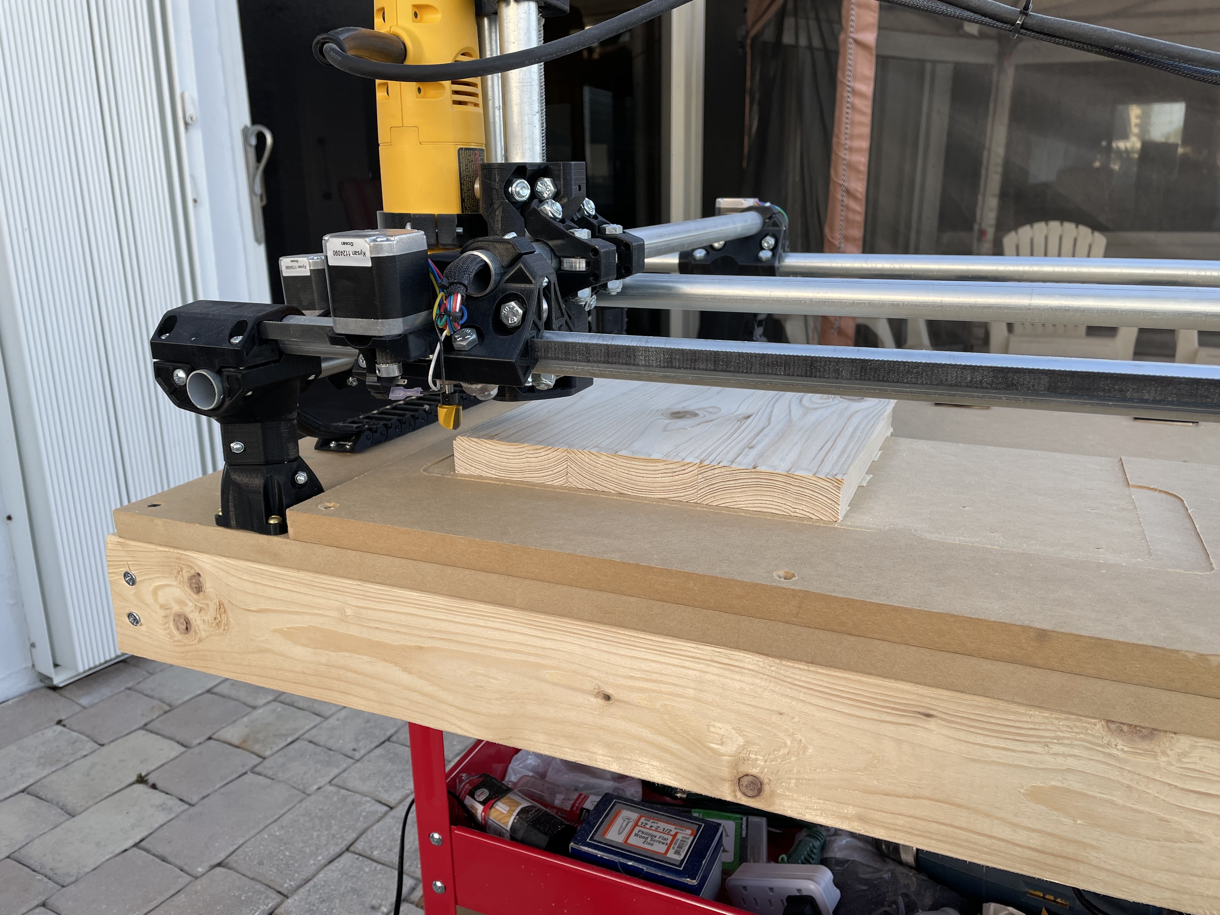
So, some time has passed, I’ve done a few projects and I thought I’d do an update about my build and what I’ve learned. Again to review it’s a default size MPCNC with a DeWalt router. It’s mounted on a harbor freight cart which lets me roll it outside and create sawdust there…
The biggest time sink I ran into prior to doing more than driving a pen was cable management. The MPCNC build plan didn’t include a specific solution for that and you’re kinda left on your own.
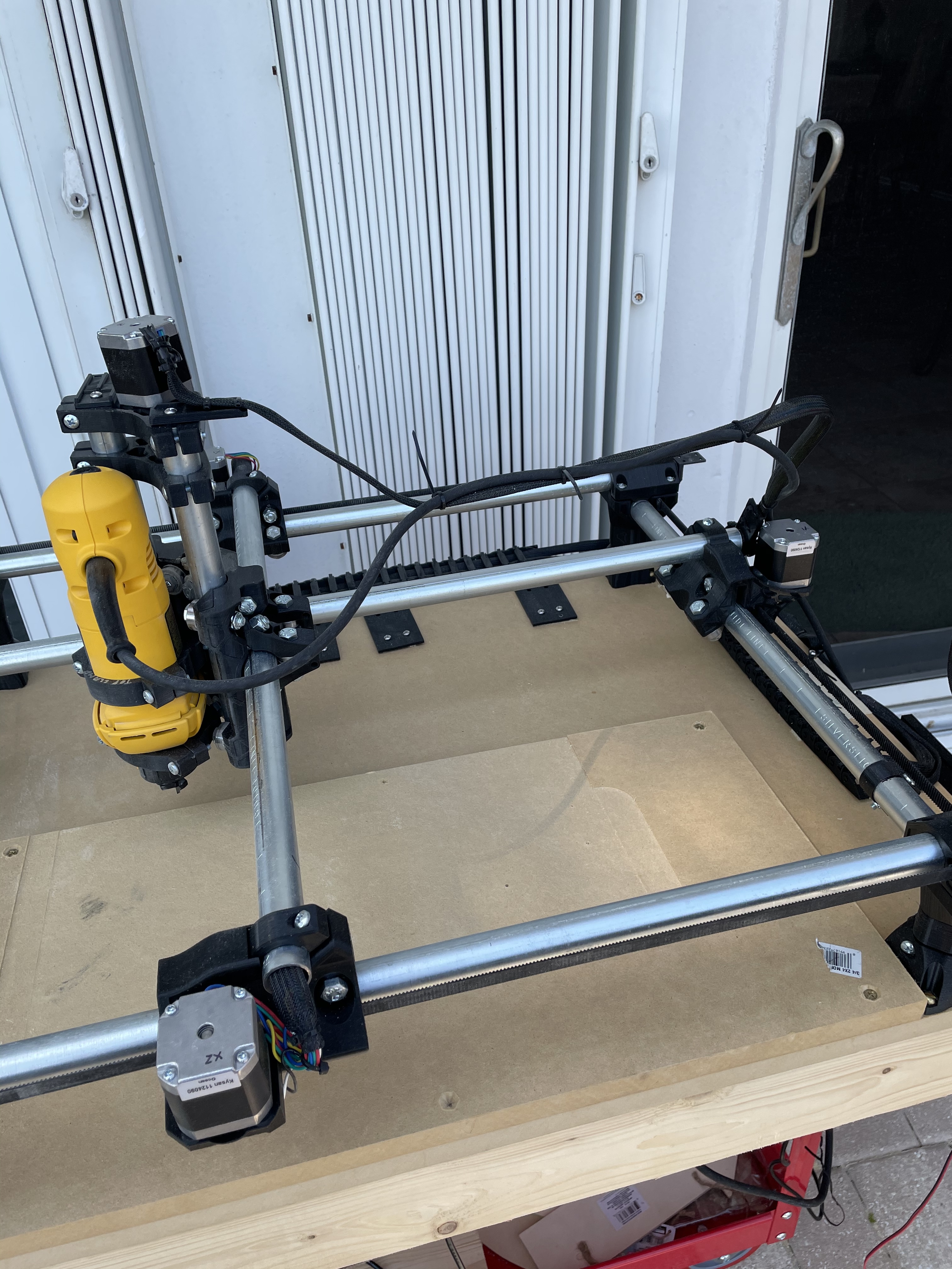
I reviewed the forums and ended up using a hybrid approach of two solutions. I used drag chains for x & y, and I used the “tape measure trick” combined with anchorable baskets for z.
X, Y1, Y2
I used a drag chain design from Thingverse and though a little fragile I’ve been pleased with the results. In particular you could print a little, try it, and print more till you had a solution you were happy with. The parts sometimes get broken and printing spares is no big deal.
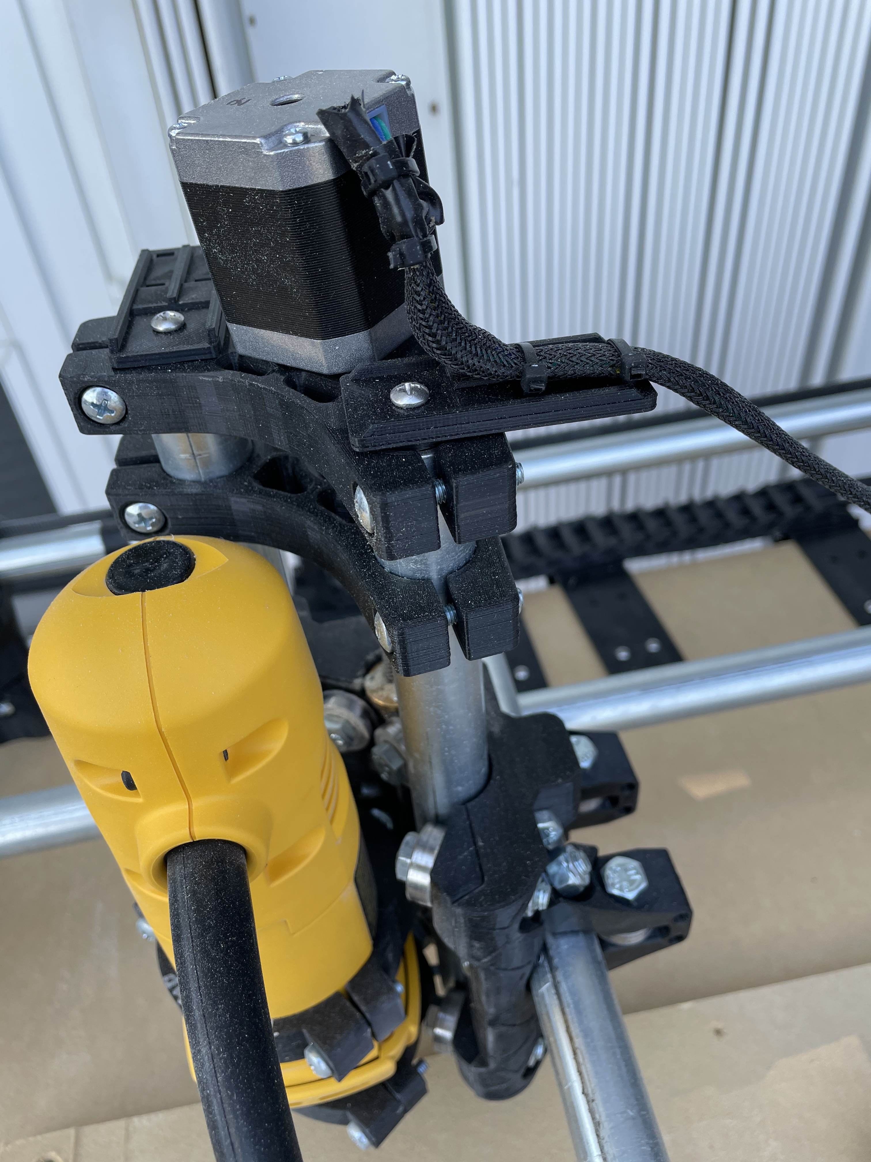
The learning curve on working with drag chains was that the way they are intended to be used is to constrain cable bundle motion into a fixed predictable area and need to be anchored on both ends.
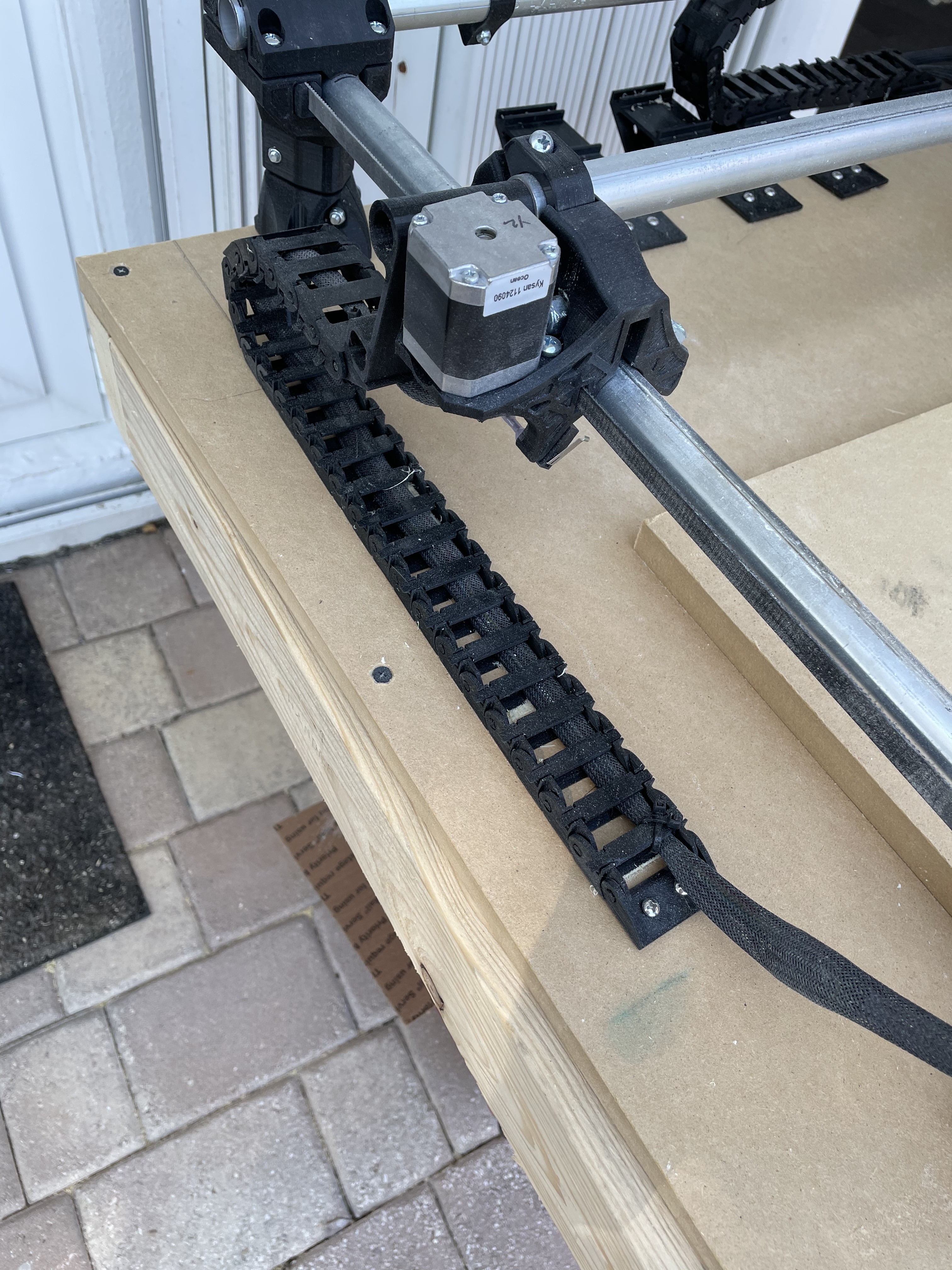
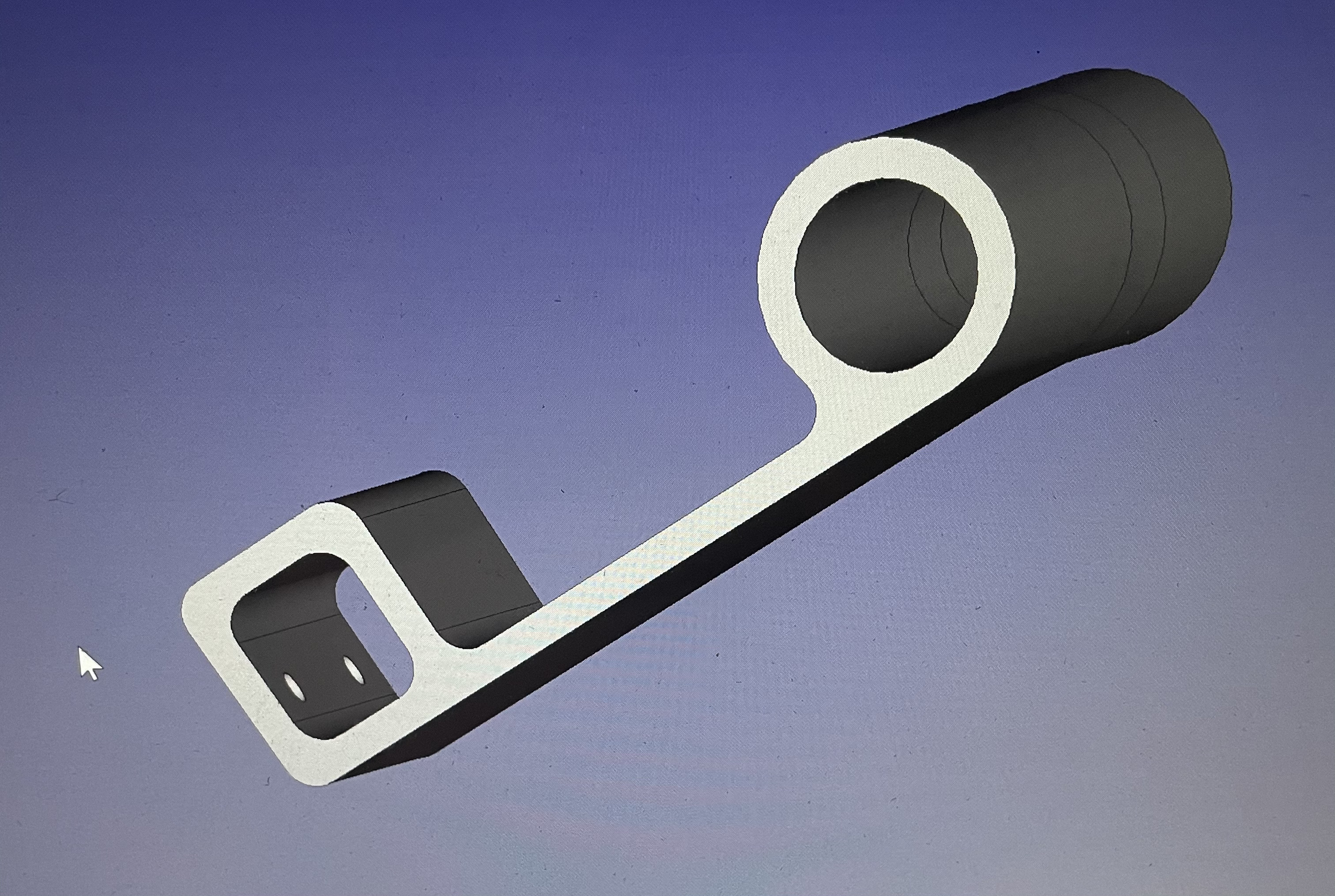
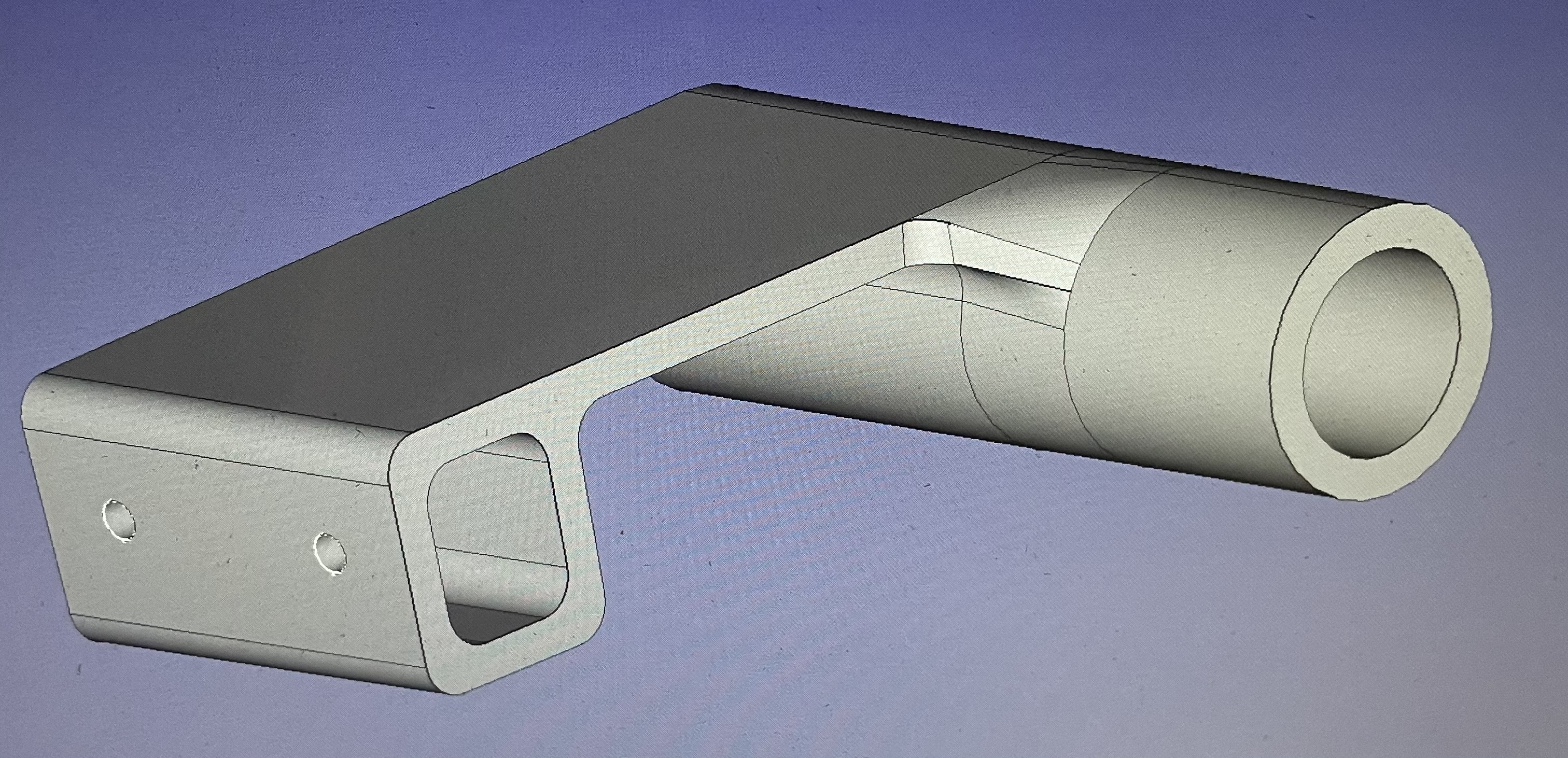
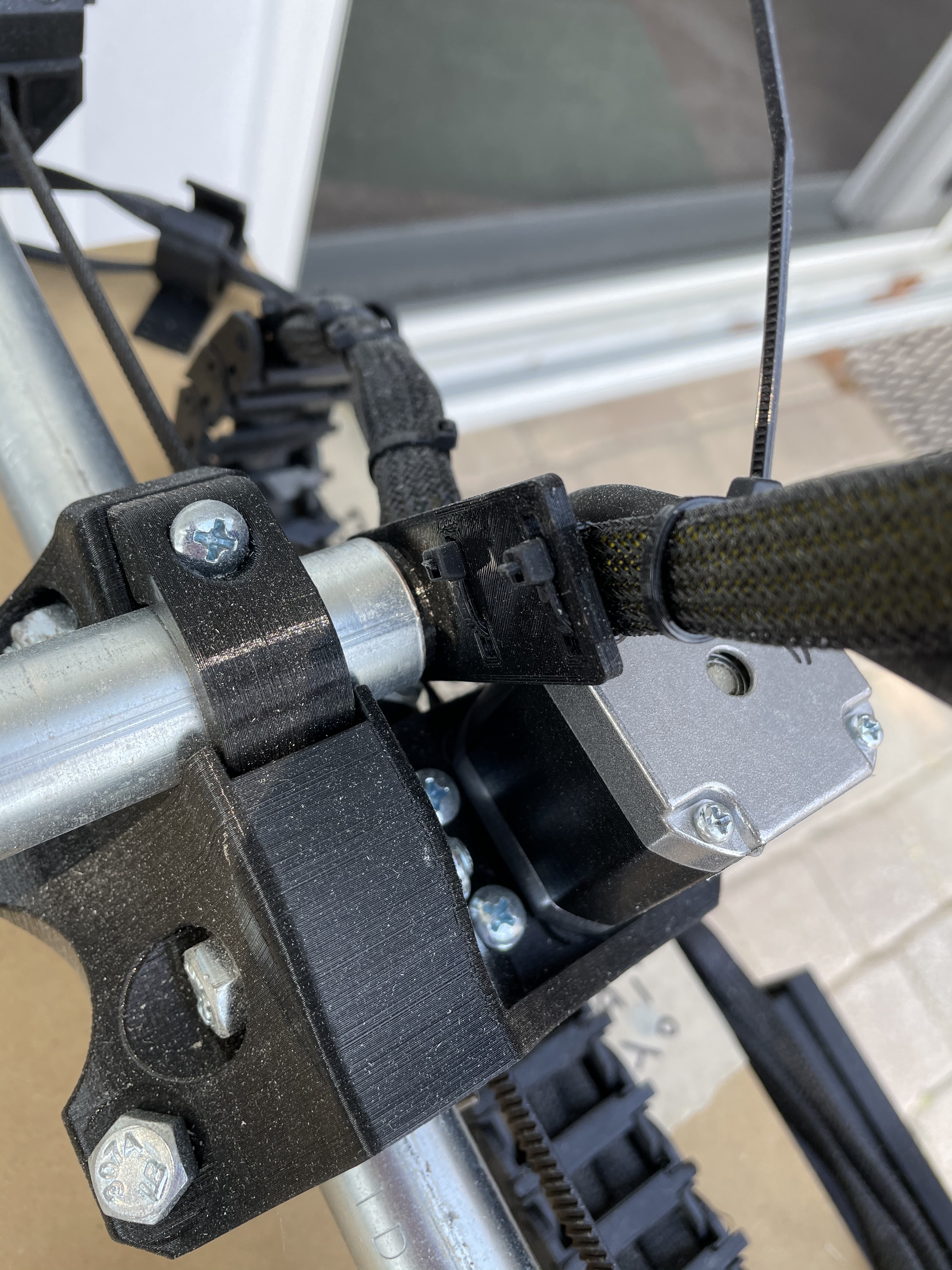
For the axis pictured here I anchored one end to the mdf table and the other end to a custom part I designed that friction fits into the EMT conduit and gave me a place to interface with the standard end piece for the drag chain.
2 Likes
This allowed me to anchor one end of the chain on the table and one end near the stepper motor.
The original author of the drag chain had conduit segments longer than the V1 calculator specified and used that to anchor the chain and so didn’t need the anchor solution I came up with.
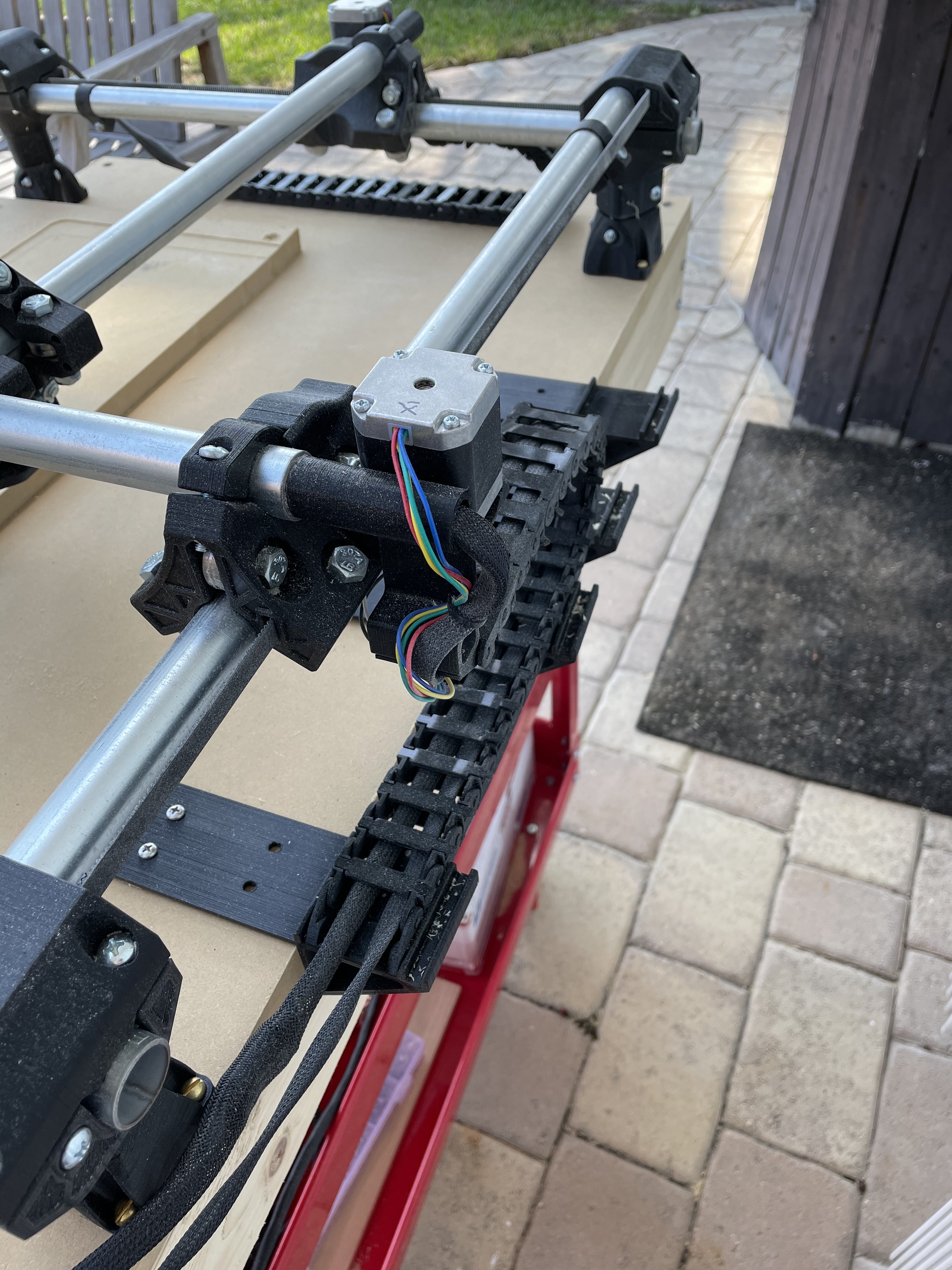
On the back side I made a 3D printed piece that is essentially a bridge for the drag chain to land on. I’m partially happy with this and at some point will do a revision where the bridge attaches to the 2x4 frame instead of the table. That will allow me to use a stock 2x2 spoil board where now part of the table is used to anchor the bridge.
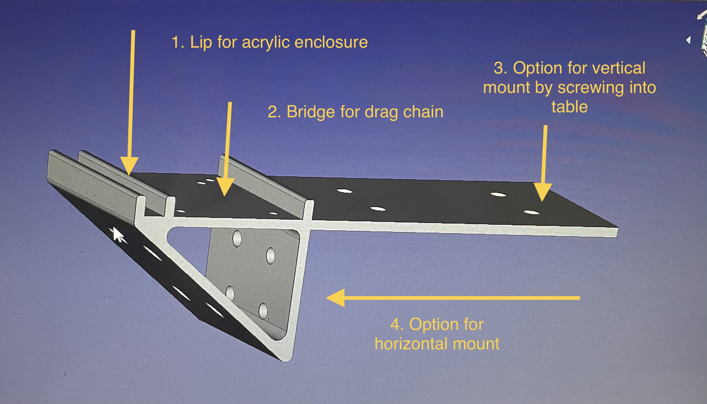
The bridge part supports the chain and was also designed to support a 6mm acrylic or polycarbonate enclosure that so far I haven’t needed or built. The number of screw holes is overkill for supporting the drag chain.
1 Like
I also used Don Gambles clever basket mounts (Thanks Don!) for some anchor points and I used them for the Z Axis cable management.
The cable sleeve came from Amazon and it took just a little more than one package to do my machine. I ended up buying two packages.
https://www.amazon.com/gp/aw/d/B071ZV6MLG?psc=1&ref=ppx_pop_mob_b_asin_title
One learning curve item about that sleeve is that in addition to needing a hot knife to seal the ends when you cut it, 500F is an appropriate temperature, and that the sleeve works better in compression than in tension so you want to cut it too long and scrunch it up (compress it) over your wire bundle and then extend it to cover the length of cable you want protected.
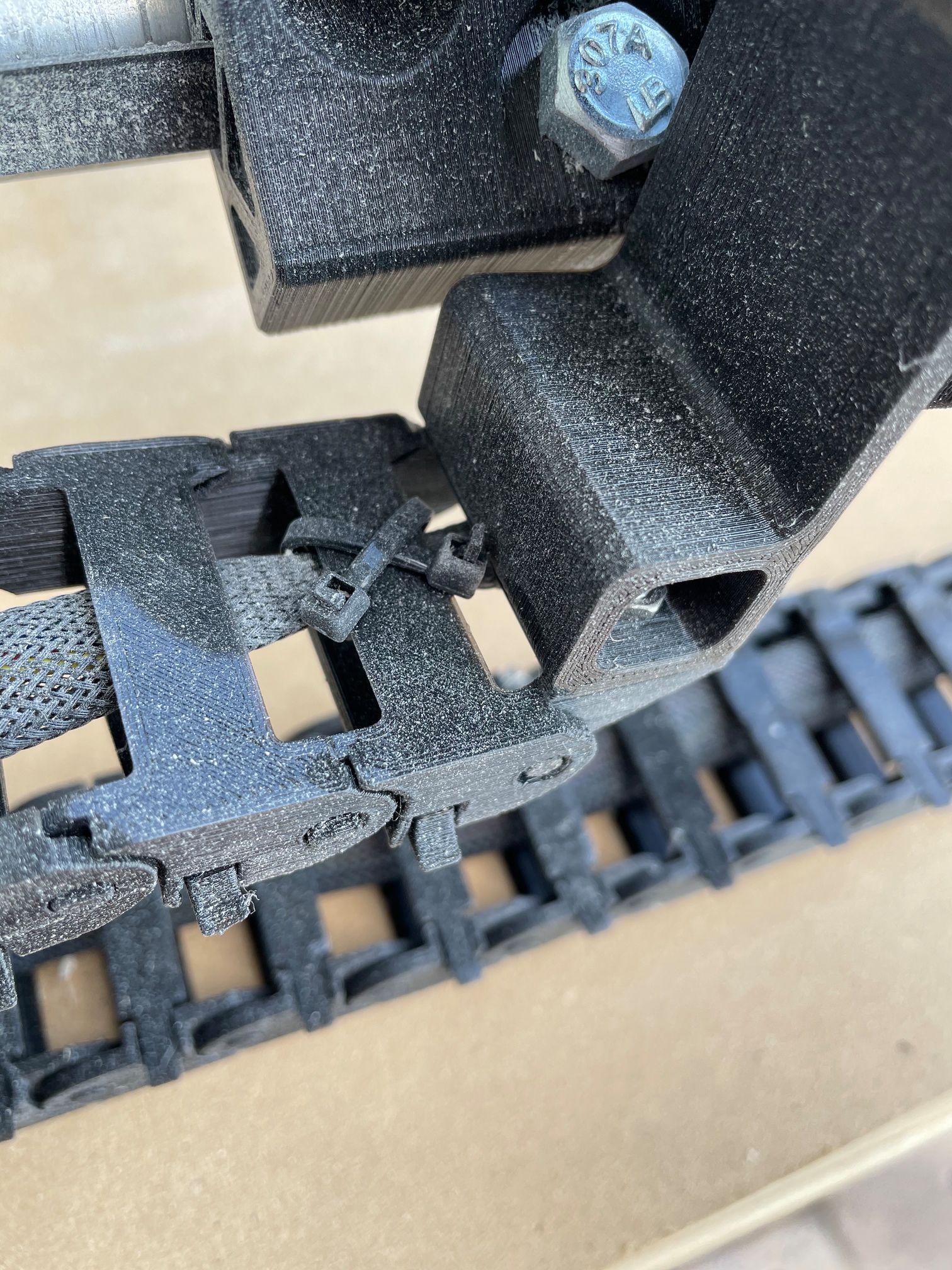
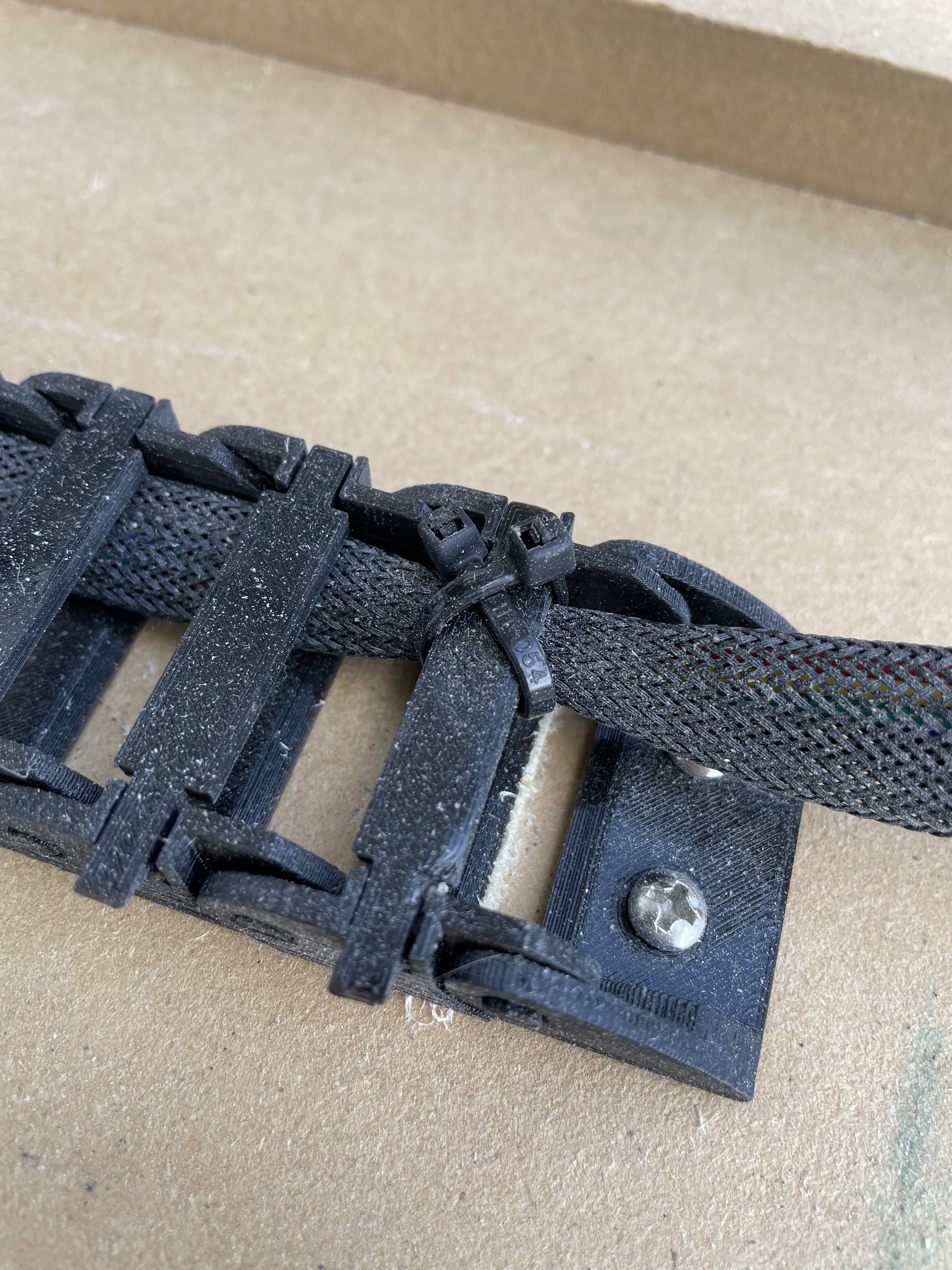
I often used 2 tie wraps in an x pattern to secure the cable at each end of the drag chain.
Along the way doing this process I bought a sacrificial tape measure on Amazon for ~$4 and thought it was a good deal. I later found tape measures for $1 at the dollar store and so that’s where I will buy one next time.
1 Like
In reading through build notes there were some comments from Ryan that the conduit didn’t need to be clamped down so tightly that it never moved and that it moving wasn’t a big deal.
I’ve found moving my cart inside and outside that the pipes do sometimes move with one annoying side effect: 0,0 can move because in moving the pipes the parts that set off the x and y end stops move.
My conduit is now marked with a sharpie as a visual cue I’m near the right position and I made some stops to get it repeatable.
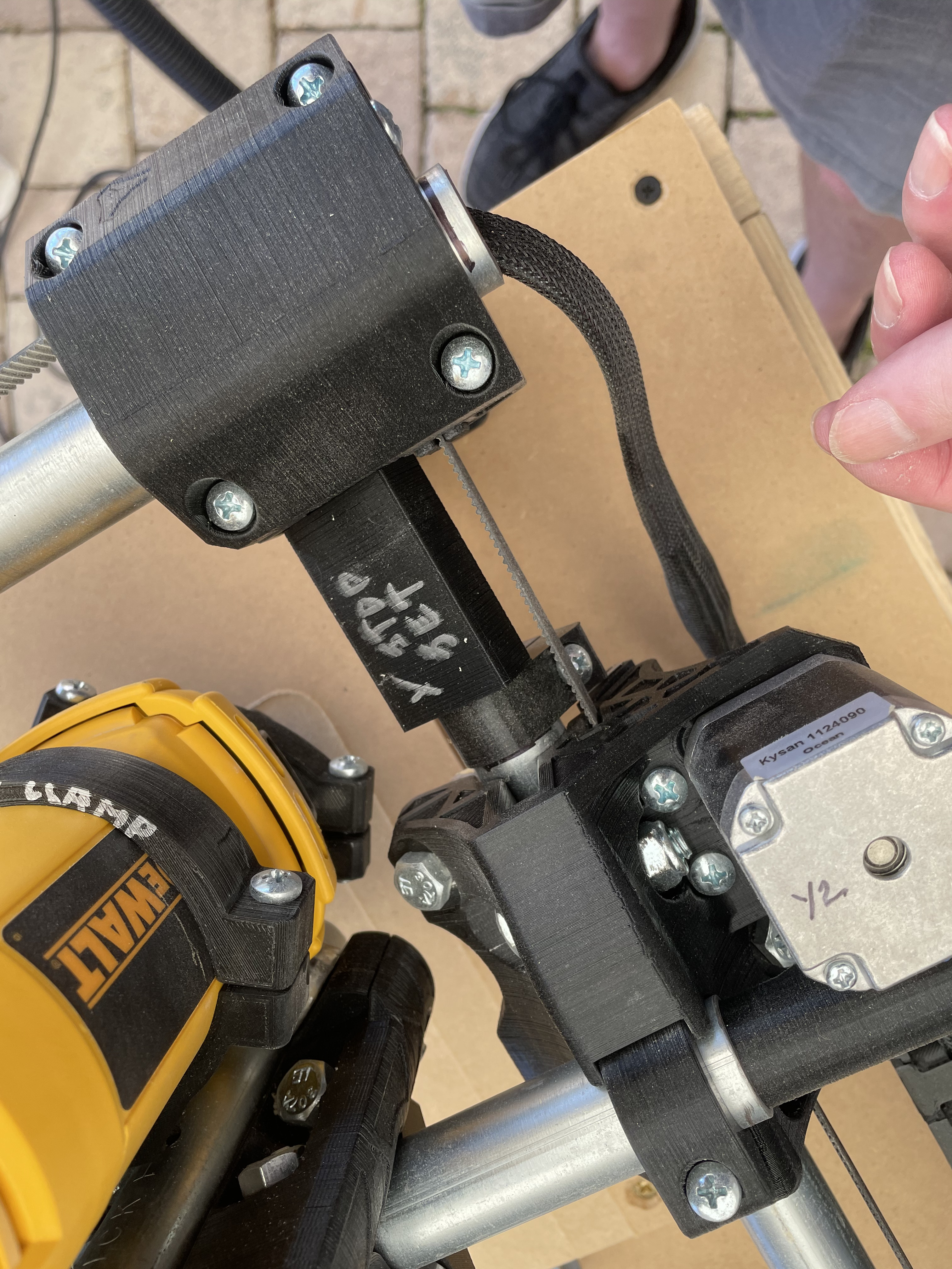
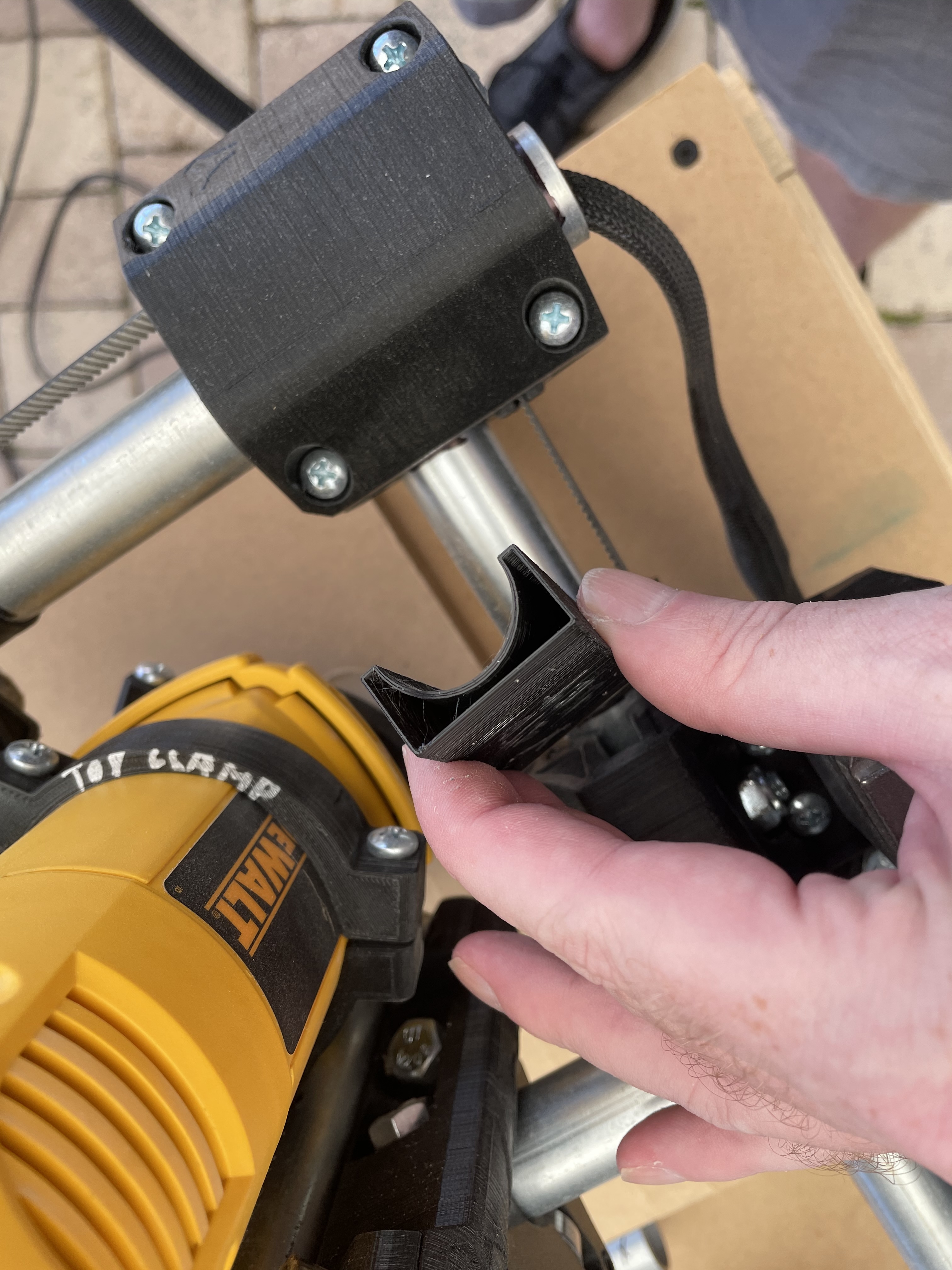
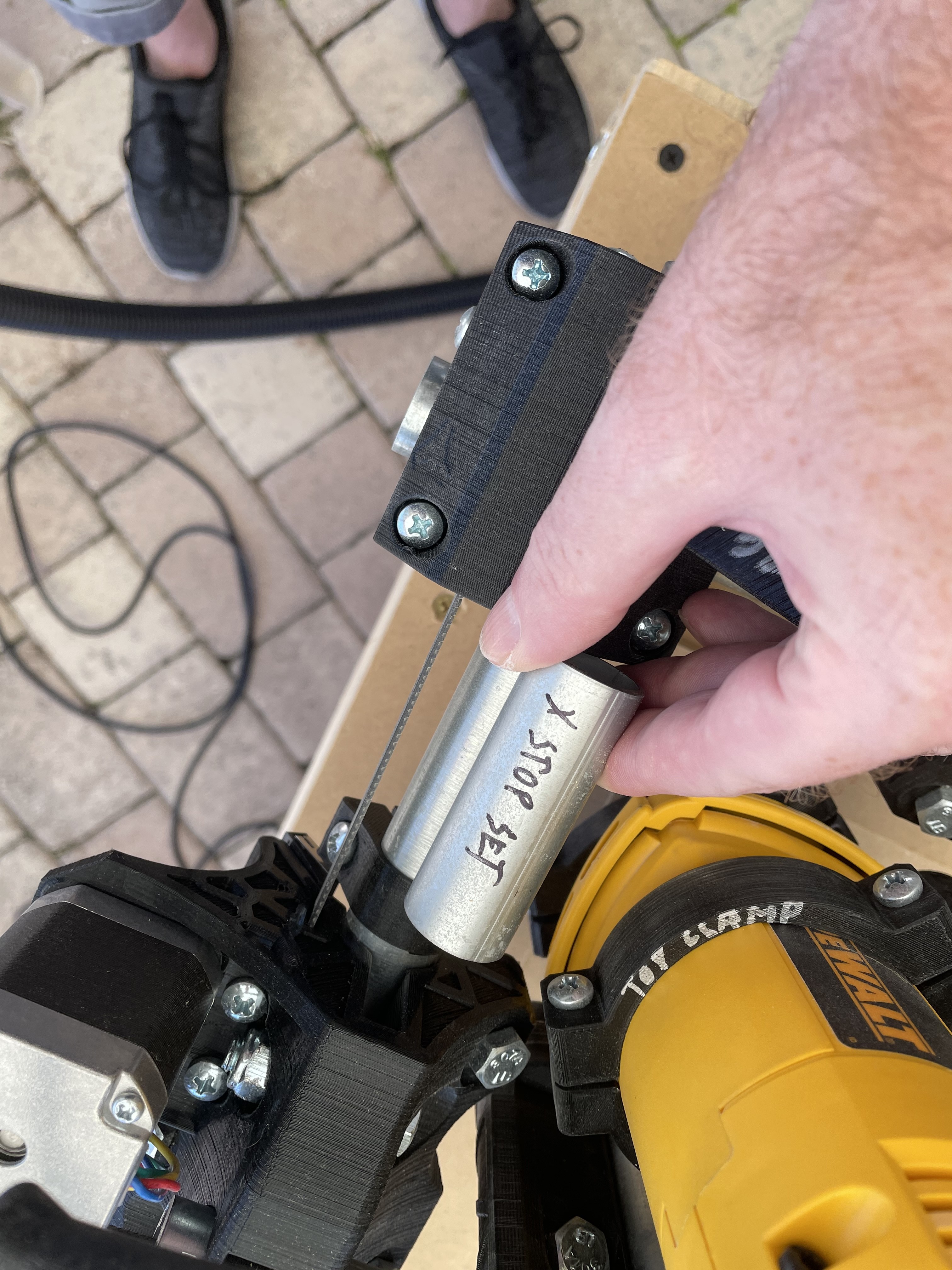
To easily get 0,0 back to where I want to to be you can use a leftover conduit piece cut to length or a 3D printed part of precise length.
1 Like
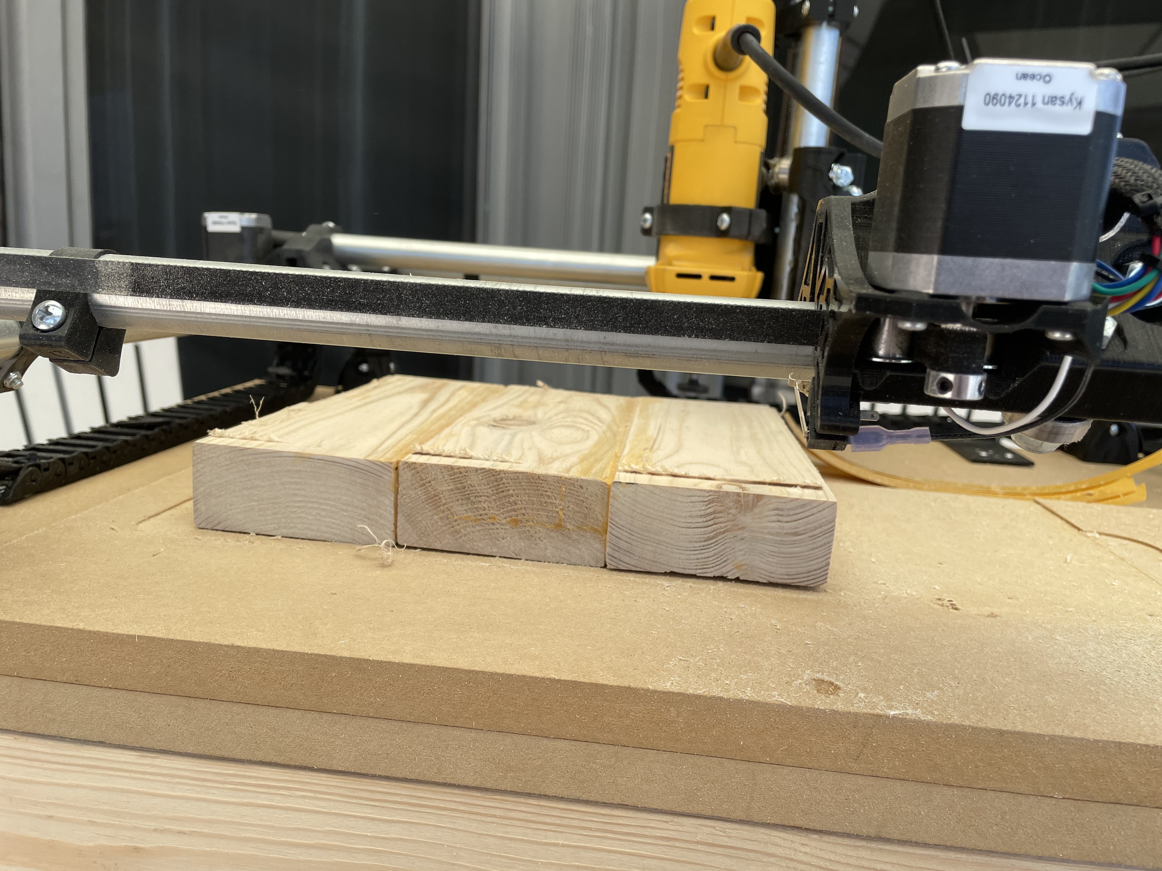
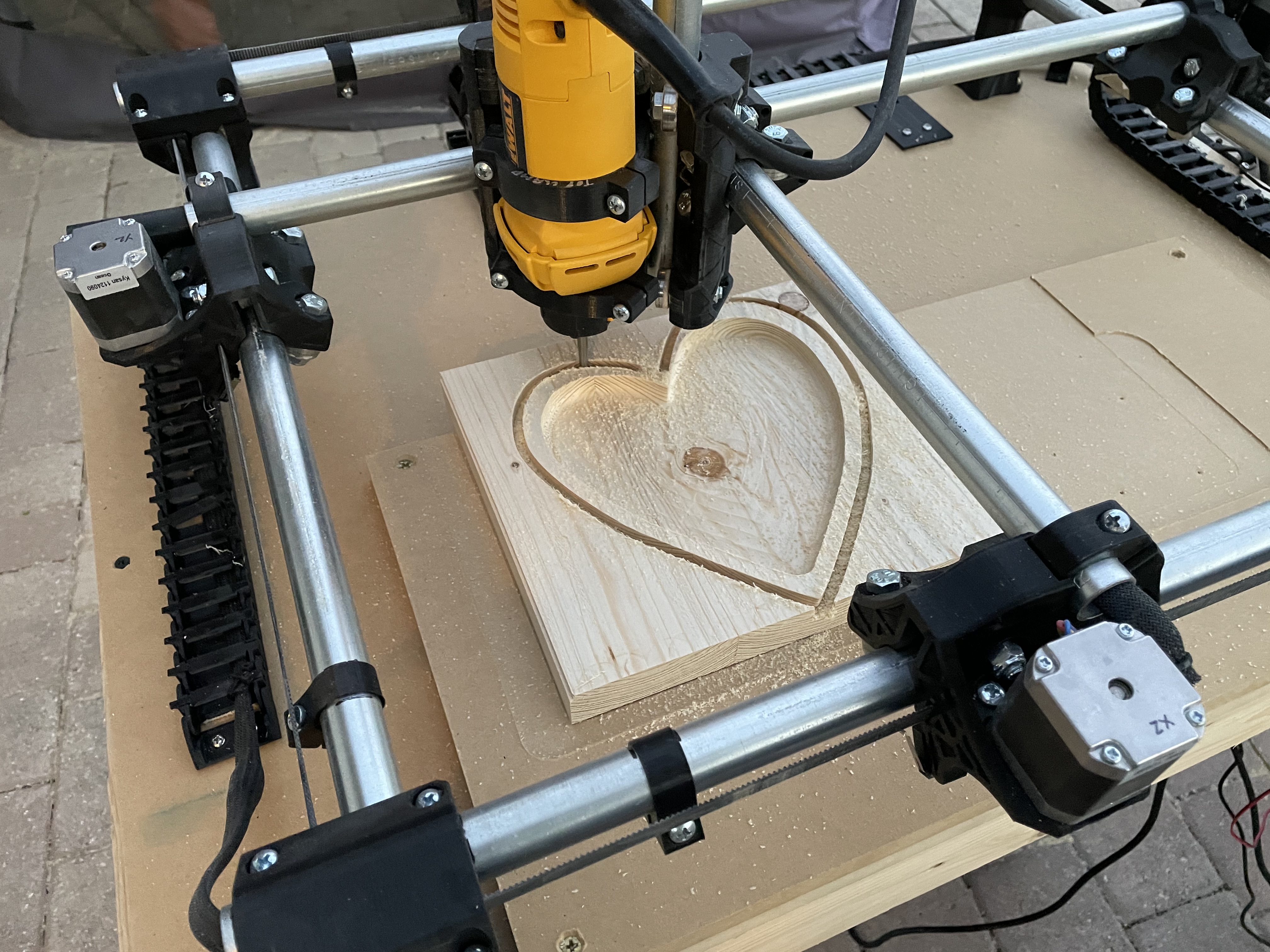
The recommended DeWalt router has no speed control yet some of the bits I wanted to use are recommended at 12000-24000 rpm speeds.
I bought a couple 1/4 inch shank bits to use with the DeWalt and had some trepidation the first times I tried them. From Amazon I got both a spoil board surfacing bit, a bowl cutting bit, and a 1/4 and 1/8 inch bit with 1/4 inch shank and both worked in pine wood (spare 2x4).
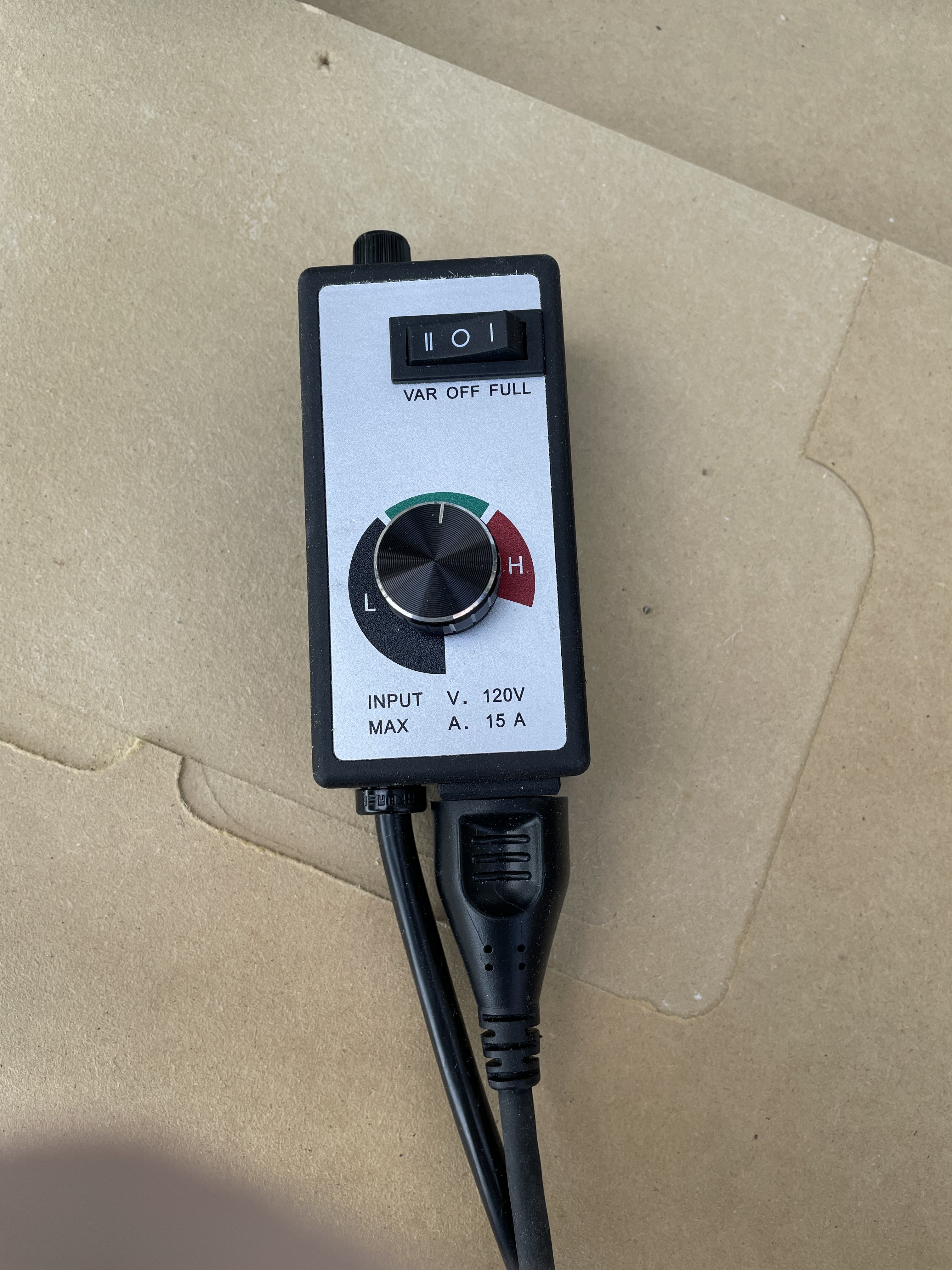
I also bought the speed control from Amazon since everything I read online predicted disaster if you ran 1/4 inch or larger bits at 33000 RPM.
The results from my first project with all 1/4” shank bits was that the world did not end at full speed but I did get better surface quality at slower speeds. Once I pushed things too hard and my double sided tape failed but that was only trying to cut a profile almost 1” deep with a 1/4” diameter bit which had that as its limits.
I haven’t used a tachometer to see what rpm the DeWalt delivered with the dial at medium and low but will at some point do that. The router seemed to handle the change in electrical input and operate slower or faster based on the dial setting.
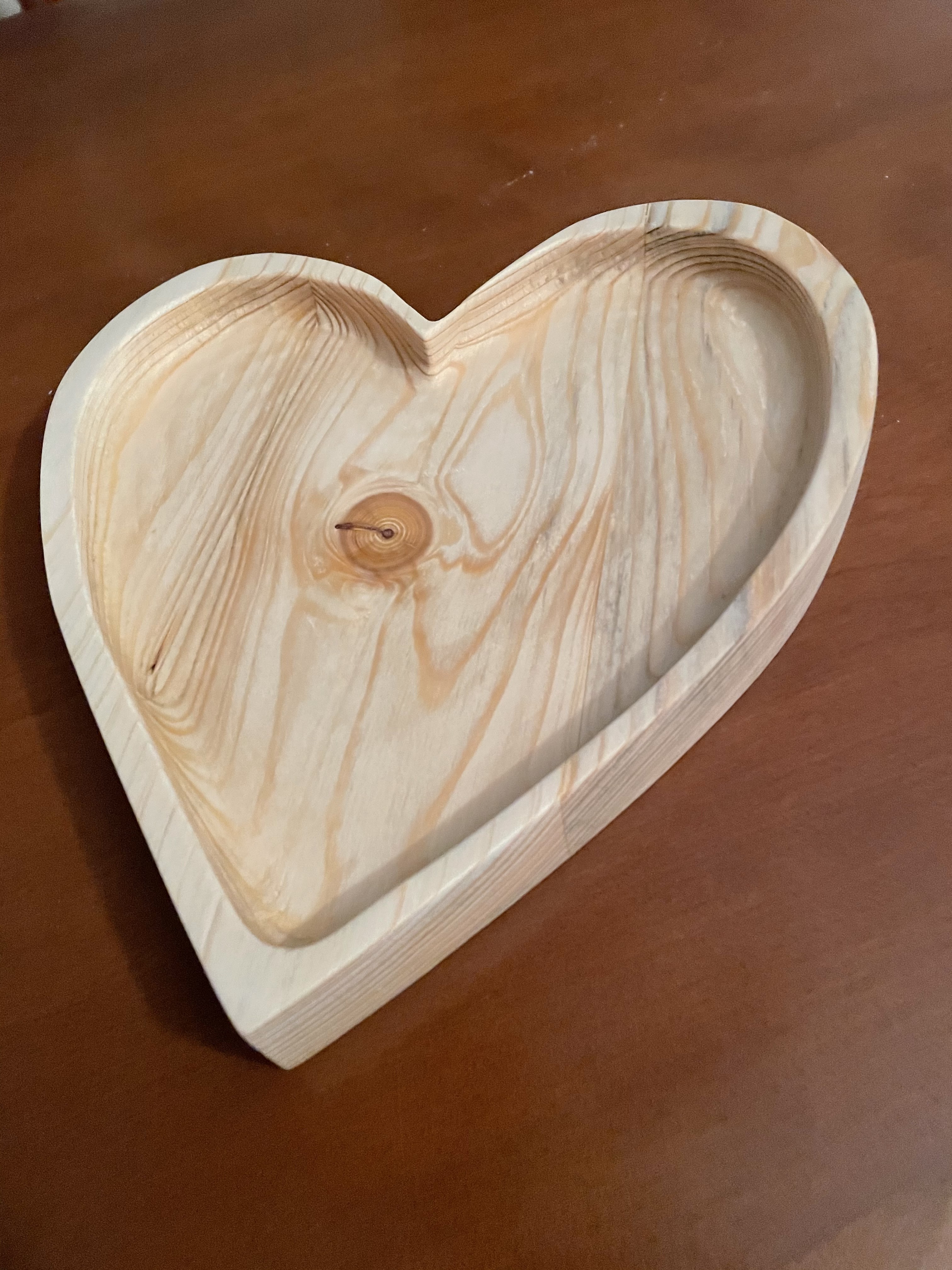
I was able to transform some glued together 2x4’s into a nice piece.
5 Likes
In addition to the pipes moving when I relocate the machine I’ve had a few of the bolts and screws that mount the router loosen over use. In addition to checking 0,0 I’ve now learned to check everything is reasonably tight before starting a work session.
My machine is probably not perfectly aligned but for these initial projects in wood it’s good enough and exceeding my expectations.
I also had one table crash with the auto z function. (I forgot to put the plate below the bit). For the curious what happened was the z stepper motor was stronger than the clamping of the plastic parts on the vertical conduit and pushed the machine apart. I was able to press the reset to stop the motion. It took a little effort to put everything back to its proper place, but luckily nothing broke.
Related to that I put the Rambo 1.4 lcd in a control tower using leftover conduit and the main board is mounted to the side of the MPCNC table.
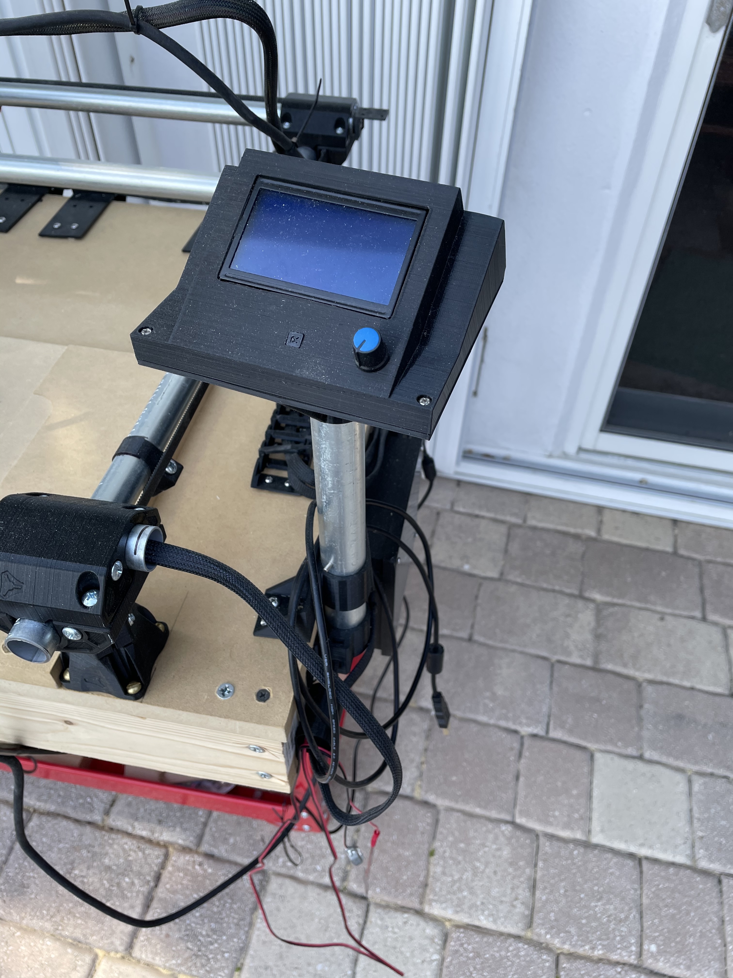
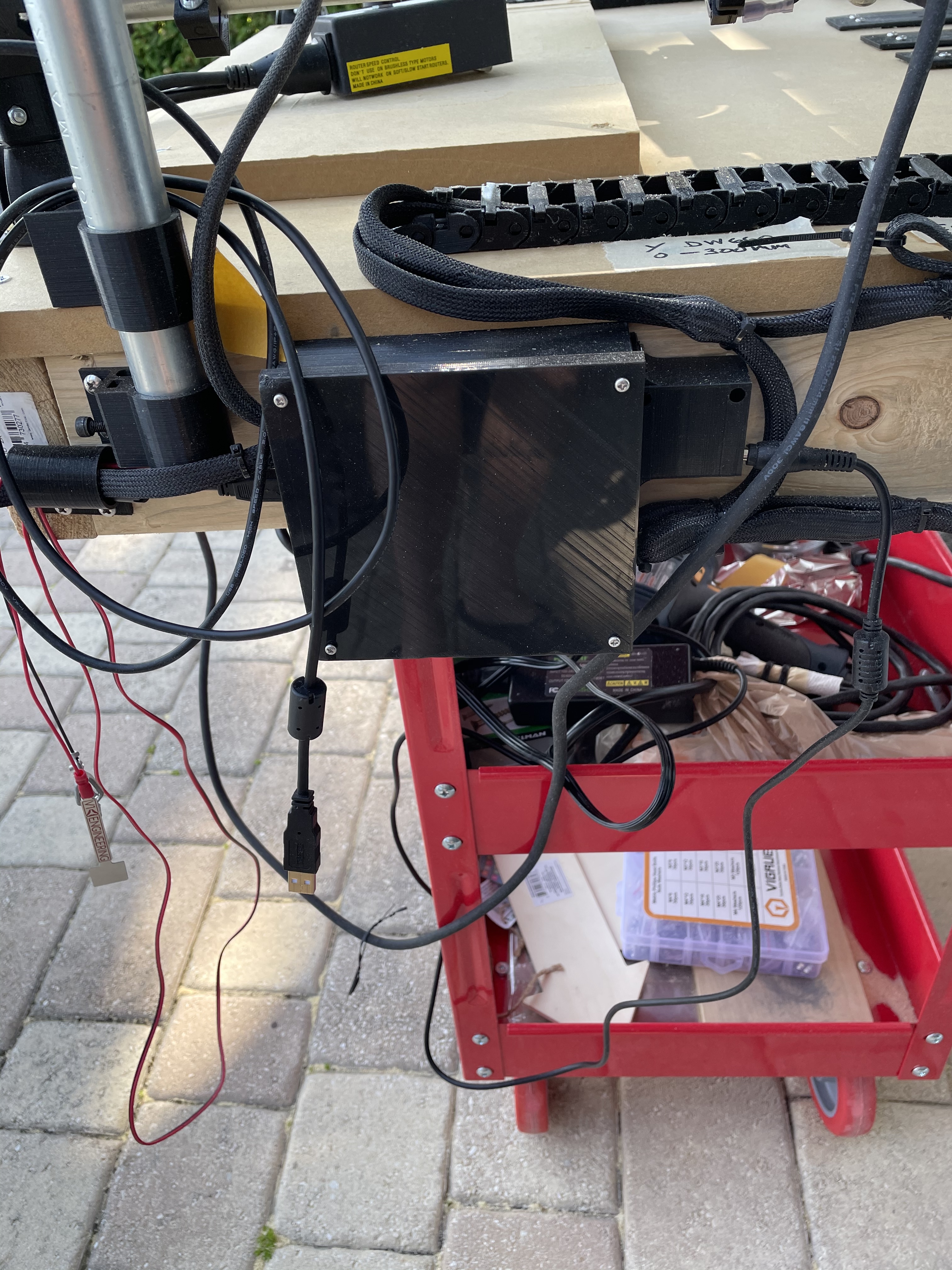
This is based on a Rambo case design by Lindh3D on Thingiverse and making 2 flat plates to make it 2 boxes.
2 Likes
FYI, I have that exact same speed controller and I found that the DeWalt 660 wouldn’t go much below about 20,000 rpm when at the dial’s minimum setting. This was at no-load, I didn’t check it with a load but I would assume it would be a bit lower like maybe 17,000 - 18,000 rpm.
1 Like