MPCNC Made In China: New Build!

Soldering directly is probably the strongest. But adding 0.1" 90 degree pins would mean you could plug it right into the motor.

It really looks great though.

Are those kind of usb cables common? All the extras I have are A to B and I have a ton of micro and mini cables now that everything is usb c.

1 Like

I am not seeing any 24 pin breakout boards. I am seeing lots with 12. I would like to find one like this, but with the female port at a right angle. I think that would make it easier to wire everything up. Maybe it would depend on the printer though:

Amazon wouldn’t be my first choice. There are a few more options on aliexpress (for much cheaper). But it is useful to still check there.

The 12 24 thing is probably due to duplication because of no up or down?

2 Likes

I have to look into this more to be sure I let this slip away on me

The one I bought is a 24 pin one. It looks like a 12 pins at first glance, but the board is double sided, one face has 12 pins and the other face the 12 other ones :wink:
It doesn’t have through holes though, but the soldering pads are not too tiny so it shouldn’t be too hard to solder.

The cable is fairly common, but maybe less common than the traditional printer USB cables with one bigger end. But they could be used too, just need a different plug on the board side!
Best of all, those cables are really, really cheap and can be sourced anywhere.
Can’t wait to make the first real tests to see how it performs!

2 Likes

Some nice progress these past days!
Almost all the hardware is done, only the carriage remains to be printed as well as a few little stuff.
I added the top frame. It’s not a structural thing so it’s not there for rigidity, i’ts mainly here to support the drag chains and provide an easy way to enclose the whole printer if I feel the need to do so later. I can also put some kind of plank over it an use it a a giant, expensive and uncomfortably high table.

Anyway, here is how it looks now:

By the way, on the above picture, all the motors are wired. You almost can’t see any wiring, it looks super clean.

Also worked on my electronics. So I built this enclosure for the Duet2:

It’s really small and compact, it features a 25mm fan (but I might change that for a bigger one if it turns out to be too noisy), and a dust filter, so that hopefully the inside stays free of metallic particles and other nasty stuff.

The USB plugs made wiring this thing a walk in the park. The double ones are for each axis (they are paralelled), and the small ones for the endsstops. There is also a tiny one on the right that you barely can see, this will be the USB-C for the whole hotend assembly.

They fit pretty well in there, but I added those little red parts so they re well secured. The lid then presses on these, which presses on the plugs, which maintains everything in place.

I still need to find a good spot to put this box in the frame.
Also I’m still waiting for my ball screws to arrive, my supplier is taking forever to make them…

9 Likes

Magnet, ball bearing, baking soda… how frivolous!

2 Likes

That controller box looks really good. Wow.

1 Like

Great news: the crazy machine made its first moves on all axis!

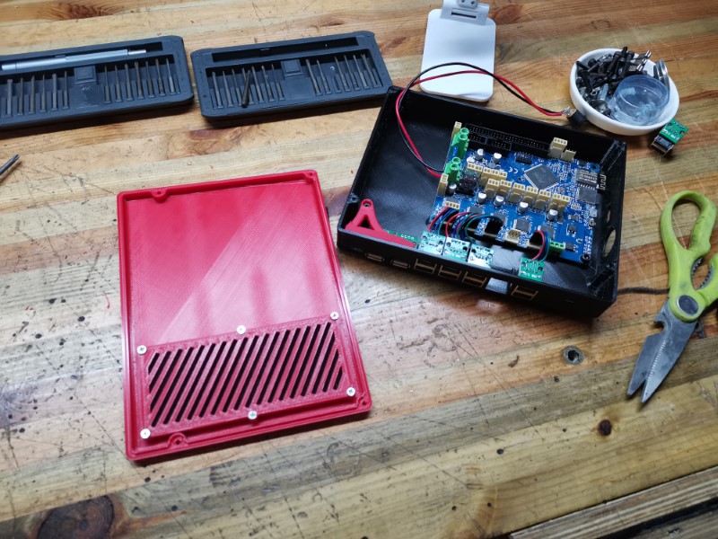
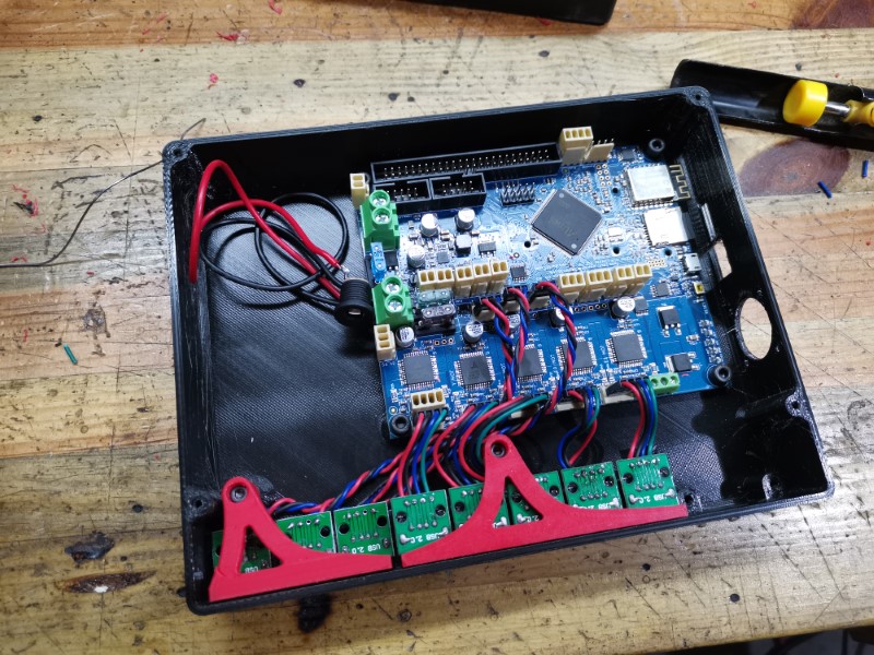
So, first I had to make the Duet work. It wasn’t particularily difficult, but I had a few trouble at first because the supplier I got it from installed a very old version of the firmware for some reason, which took me a really long time to figure out and correct.

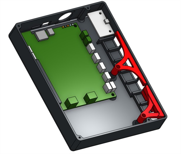
In case you’re wondering what a Duet is: this board is kinda next level stuff: you can control everything from your compter/phone/tablet remotely, using the browser. Kind of like octoprint, but it seems to be easier to use. It features some really great stuff, like the fact that you can change things like your stepper direction, driver currents, steps per mm and basically everything that would normally be present in the Marlin “configuration.h” file in just a few clicks!
It also features more drivers protections, which is a good thing otherwise I would probably had fried tthem already. It seems like you can disconnect the steppers without too much risk. You’ll even get an alert if one stepper phase is disconnected or doesn’t work properly!

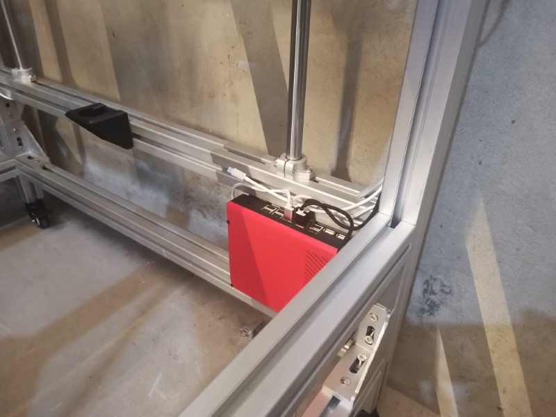
So far I find it really awesome, the wifi connexion is stable and very responsive too, no delay whatsoever. It was a bit expensive, but so far I find it worth every penny.
Still a lot more to experiment on this though, let’s wait until it prints before getting too enthusiastic!

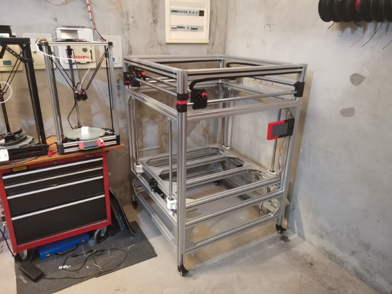
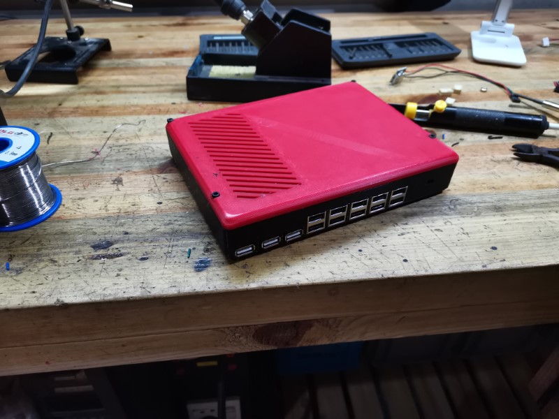
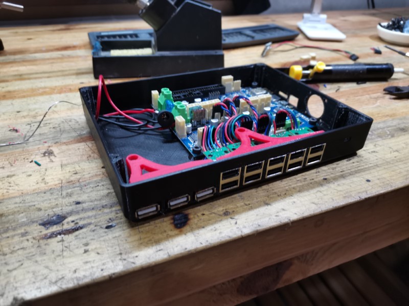
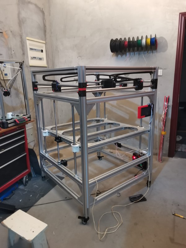
Anyway, I installed the enclosure here and made sure the wires could physically connect to it. So far so good!

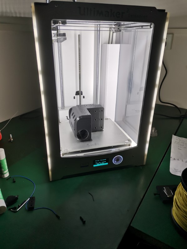
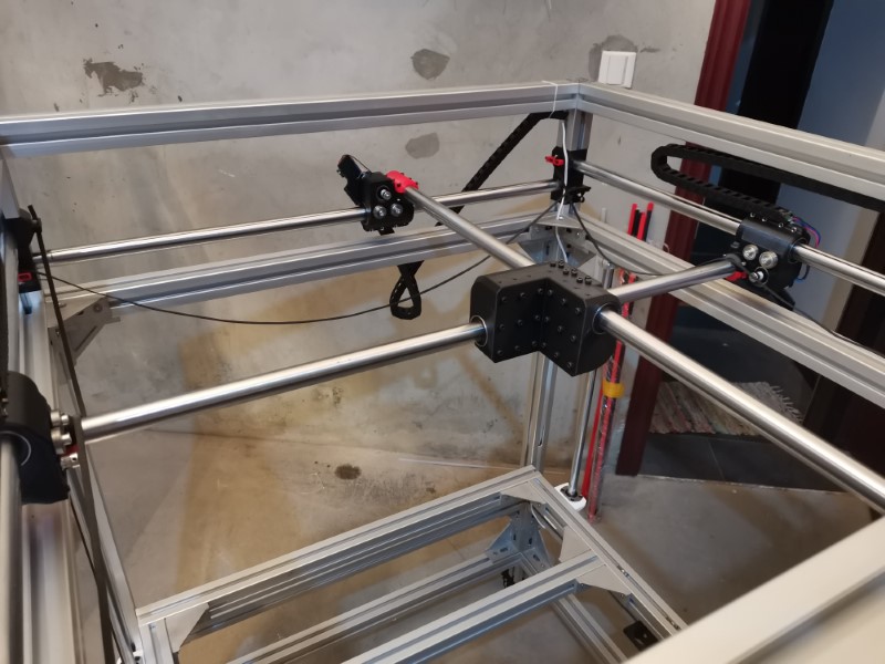
Also printed the central carriage. This thing is massive, it took litterally more than half a spool of plastic to print (550g according to my slicer)! It was printed with a 50% infill and 5 loops and took about 22 hours to print. Used the ultimaker at work to hopefully get it squared better than my delta printers could:

Weird thing is, after installing it in the frame it looks tiny:


Total weight including the linear bearings and the screws was measured at 1.3kg… That will have some inertia for sure… Hope it won’t be an issue, but I guess it will be similar to when I had this giant Z axis moving around before.

So anyway, I finally received my ball screws, so at first I installed just one because I had to wait for a second belt to arrive:

…But in the end, I couldn’t really wait so I just gave it a quick shot, just to see if it had a chance to work… And as it turned out, it worked well behond my expectations: One relatively small nema 23 stepper was enough to lift the whole bed structure with really decent speed!!

So that’s really great news for me, adding an other motor will double the power which should be more than enough to lift the whole thing with the added weights of the bed, glass and everything!
The other axis are much more silent and they are fast and responsive too.
Next step is to design a print head system and start working on the bed.

16 Likes

Nice! Are you using Marlin 2.0 or something else?

1 Like

No, I think it’s using something like reprap 2.xx or maybe 3.xx firmware. So far it seems nice.
That was my biggest fear actually, having to ditch Marlin.
Now that I think about it, I need to check if my slicer is compatible with it, I’d hate to have to ditch my good ol’ kisslicer, not a big fan of the other ones.

Currently building a CoreXY printer as well but not thaaaat big! :smiley:
Really nice work so far!

1 Like

Reprap firmware is good, just need to get your head around the fact it’s almost entirely Gcode, even the setup.

1 Like

No heated bed? Or are you going to use multiple of heatpads?

The bed will be heated, that is not optional on such large machines, you get a lot of warping otherwise. So far my plan is to buy a large aluminum plate and probably use several silicon heat pads. Not entirely sure yet, I need to finish designing my print head first and then I’ll start tackling the bed.

I find this solution to have several advantages: a large thick plate of aluminum should be rigid, transfers heat well so it should remain uniformly heated and it is not as expensive as I thought it would be. Using several heat pads instead of a single large one means I should be able to install some adjusting screws all over the plate to correct its flatness in the middle as well as the sides. I see very few downsides aside from weight, which hopefully won’t be an issue. And even if it turns out to be an issue, I can overcome it by using larger motors with external drivers.

I don’t want to cut corners on this machine to save a few bucks, this time I intend to do it right!

Keenovo (I think I’ll buy my heating pad there) can make custom silicone heating pads, or on AliExpress for instance you can write the sellers if they can customize their pads as well.
But I think for that bed size you’ll need some Watts… :nerd_face:

1 Like

Yea, that’s who makes my heater as well. Works beautifully. Still on the fence on whether I should physically attach the heater, or keep relying on the adhesive. It’s an acrylic adhesive, which I’ve read that gets stronger the hotter it gets, so :man_shrugging:. Mine is 110 with a ssr doing the switching off the heat bed pins on the duet.

I’ll go with 220V. :nerd_face: Respective SSR is already installed but the rest is missing…

Since you have a mill, then you can mill out a channel, add a gasket and a back plate, and pump hot water or glycol through it.

I’ve never seen anyone do that for a 3d printer, probably because it’s a bad idea.

Not really hot enough.