MPCNC Made In China: New Build!

Hi Mr. Dui. Congratulations for your build!
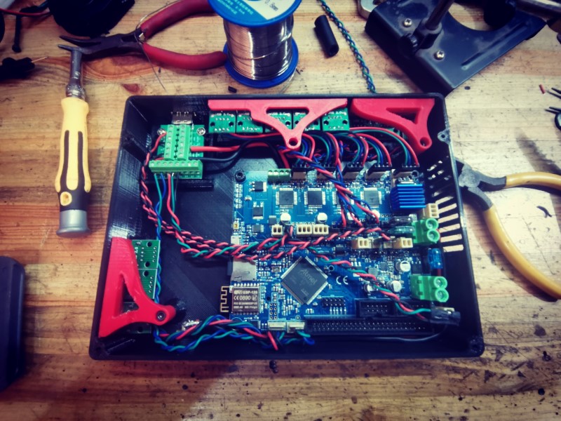
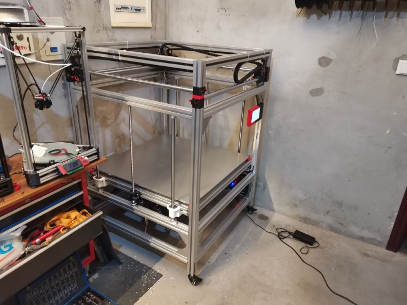
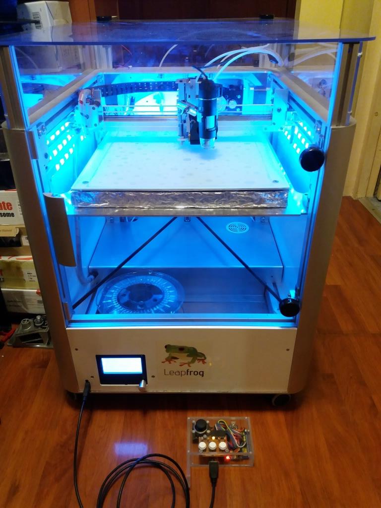
Some time ago I have upgraded my Leapfrog Creator (a big printer, similar to your build; ok, not that big…:slight_smile: ). Even attached Armin’s controller to it…by USB cable.

So been there, did that.
If you take my 2 cents, here they are:
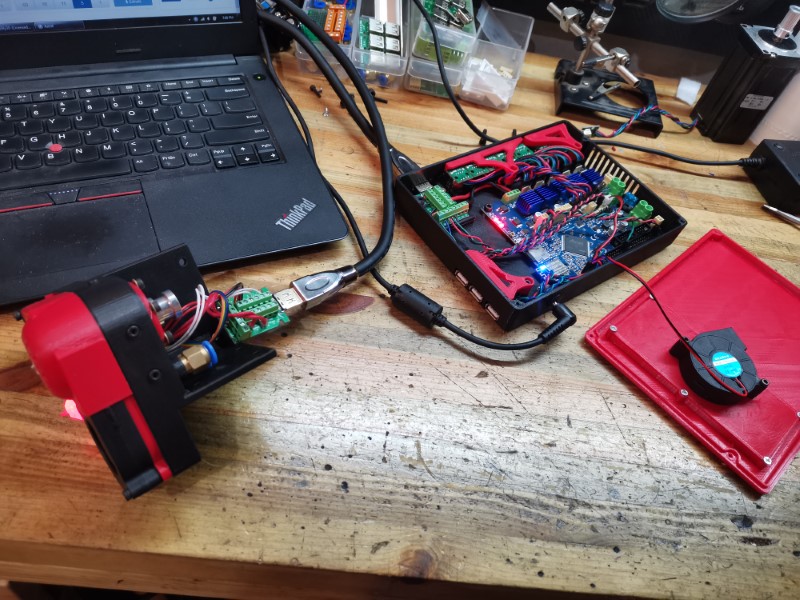
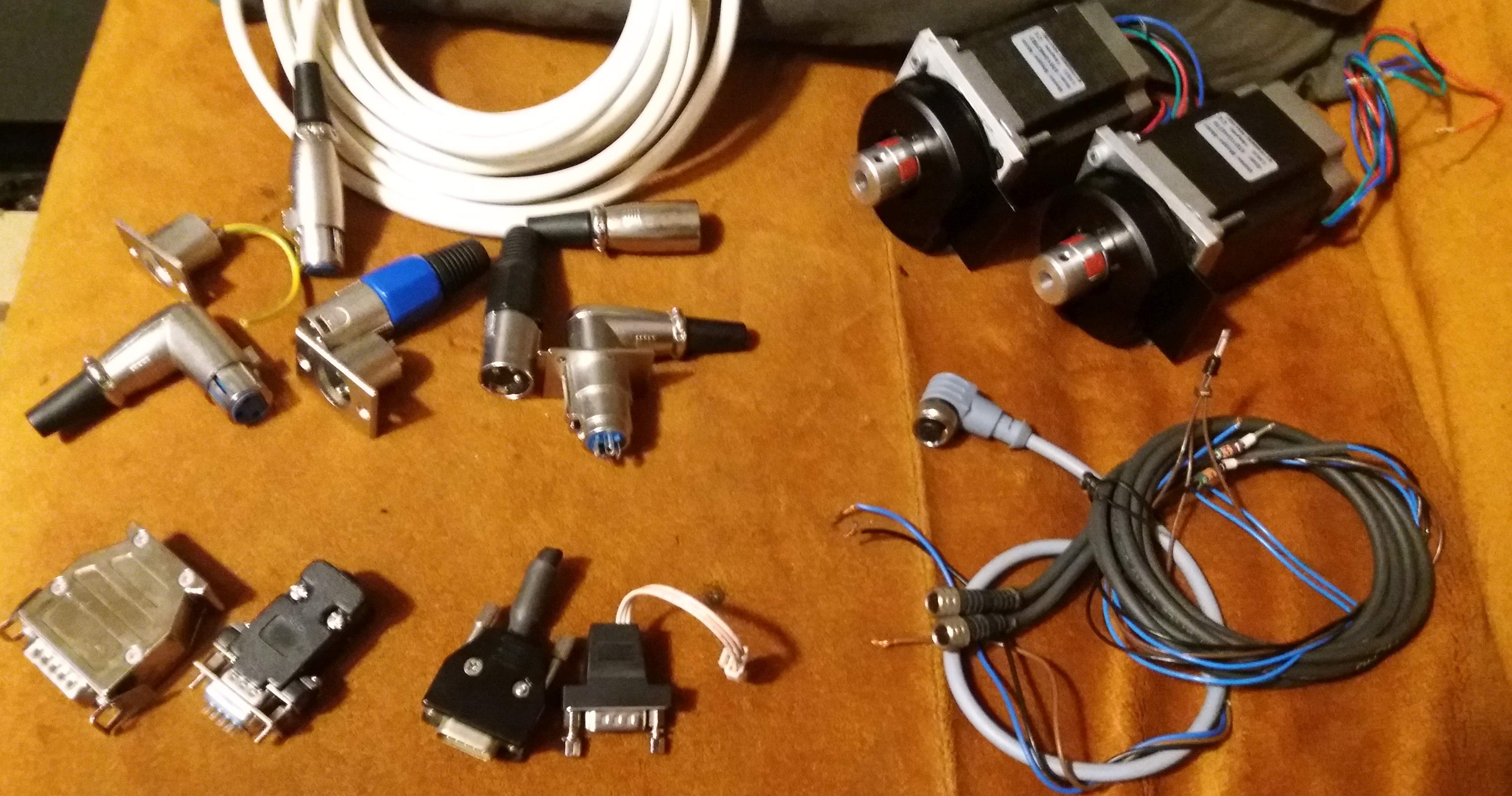
I have thought of using USB cables allaround for connections of different modules but I gave up. If you have been somebody else with a regular printer I have had adviced him to try it -maybe fix USB connectors with hot glue or zip ties.
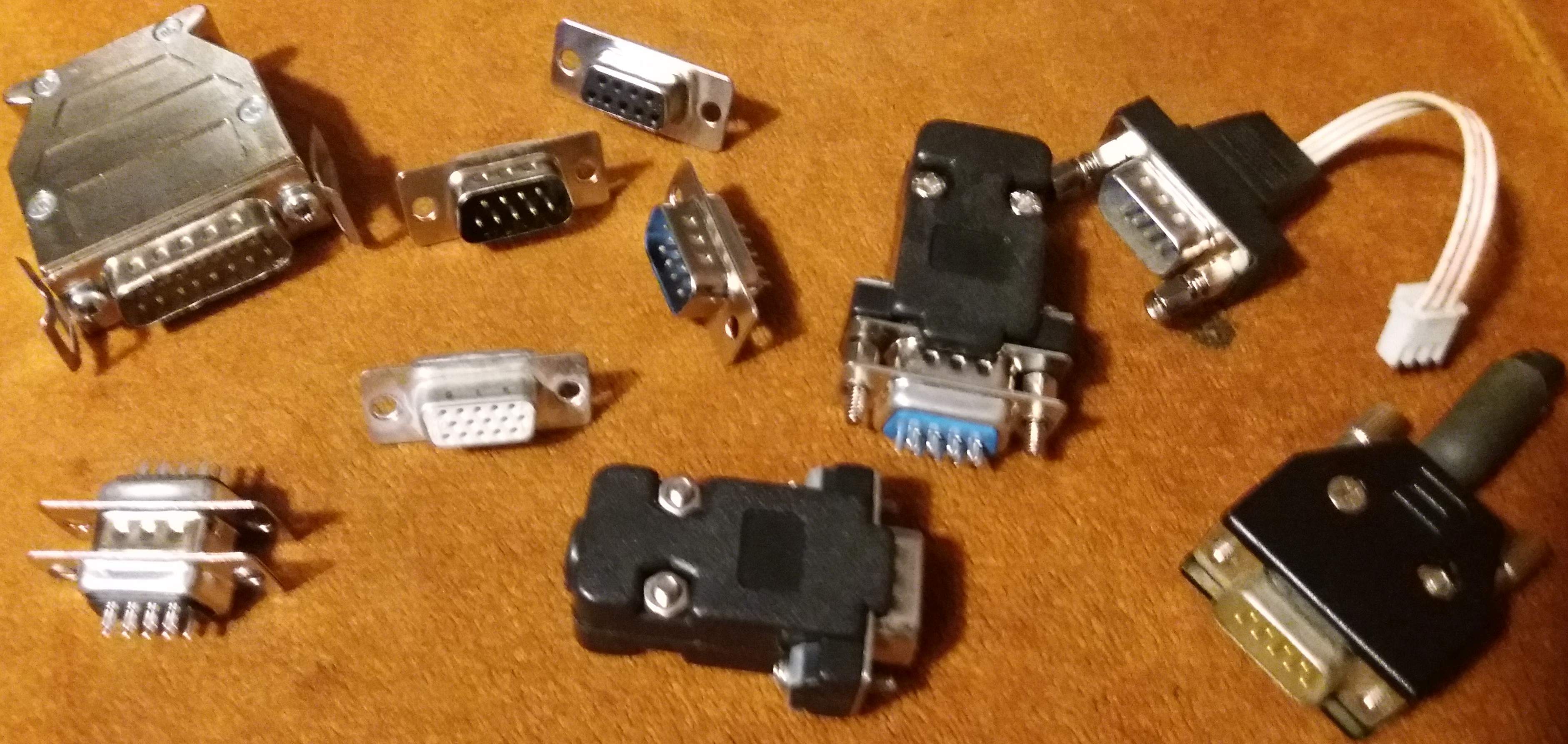
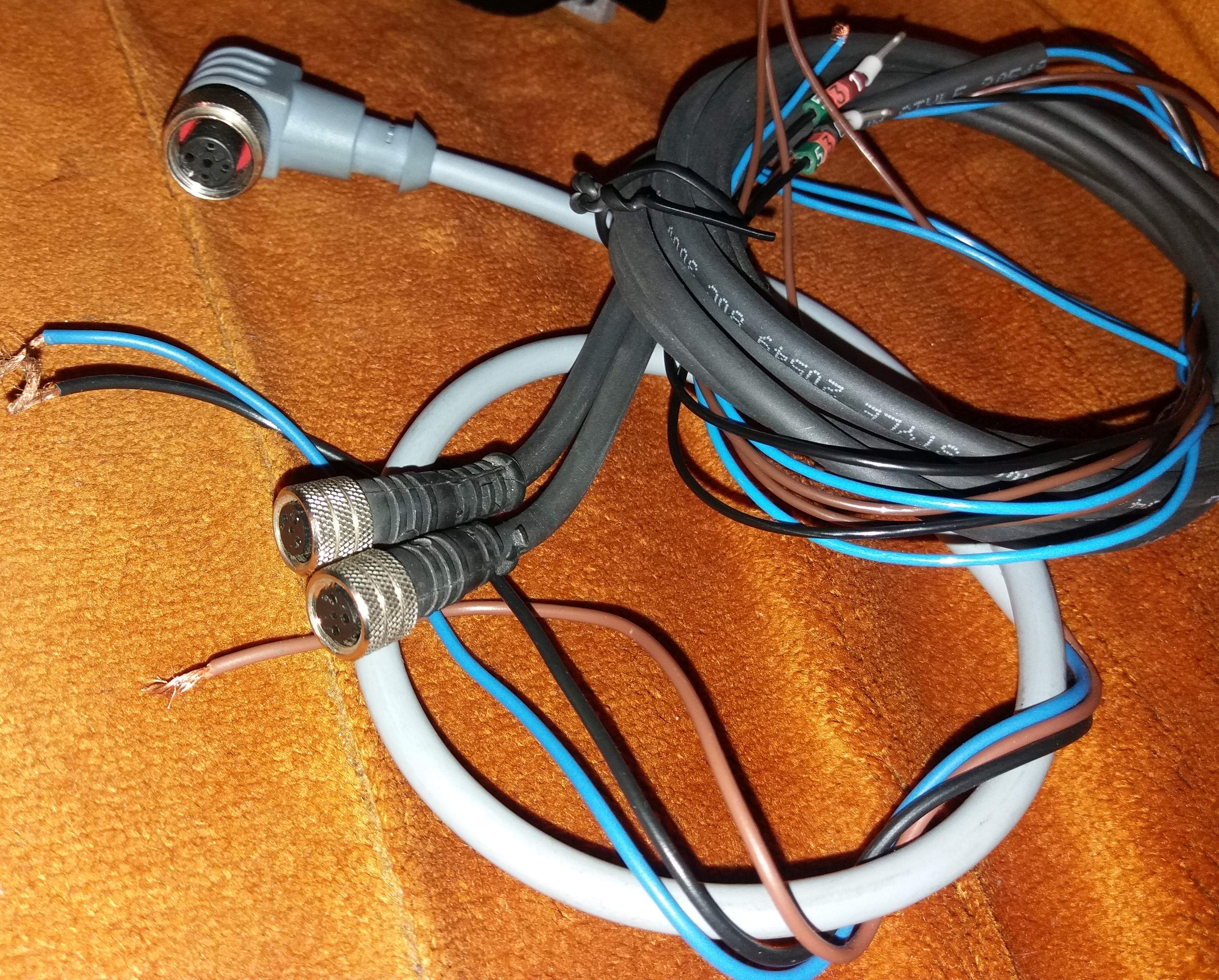
But you want to build an industrial grade printer and everything should match that. Here are downsides of USB cables, Wires inside are too small for power requirements. Never calculate wire section to the limit. Stepers need bursts of current to give their best, so the larger the better (copper section). Cables might suffer damage-even from assembly stage -which reduce effective section. Normal USB cables are not built for all arround the clock bending/ pulling/ shape change. Most exposed in the cable are the terminals where change in stiffness appear. This concentrates mechanical stress.The USB cunnections themselves are not made to compensate long time these kind of stresses so they might loose the good contact. From my history I can tell I have lots of old USB cables that don,t work properly -either interupted, or making random contact. This is a killer for robust design. Best from USB family would be Micro-USB which have hooks to keep connection secure and are made for frequent connection and certain mechanical stress. Never evaluated USB-C but I know I have connection issues with USB 3.1 sticks. HDMI connector retention seems to be better, but how it will work - I don’t know. I prefere DB15 where you can customize a lot concerning wire section, order of wires, and you have a lot of pins available. There are also small size versions and I guarantee -fitted on your machine- they won’t look that bulky. but if you look for small size and modularity, there are lots of FSC8 and alike cables and connectors for industrial proximity sensors. They ar built for industrial processes and match the intent.


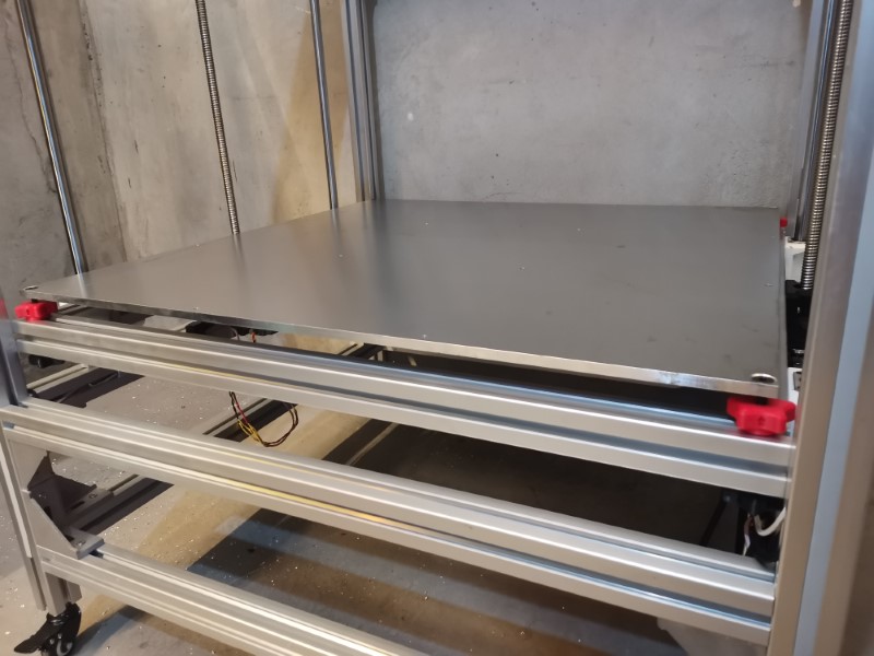
Regarding Heat bed, though i think motors can cope with 40kg weight, ball screws have high degree of reversibility. That’s why I would use counterweights/pulleys to compensate dead weight.
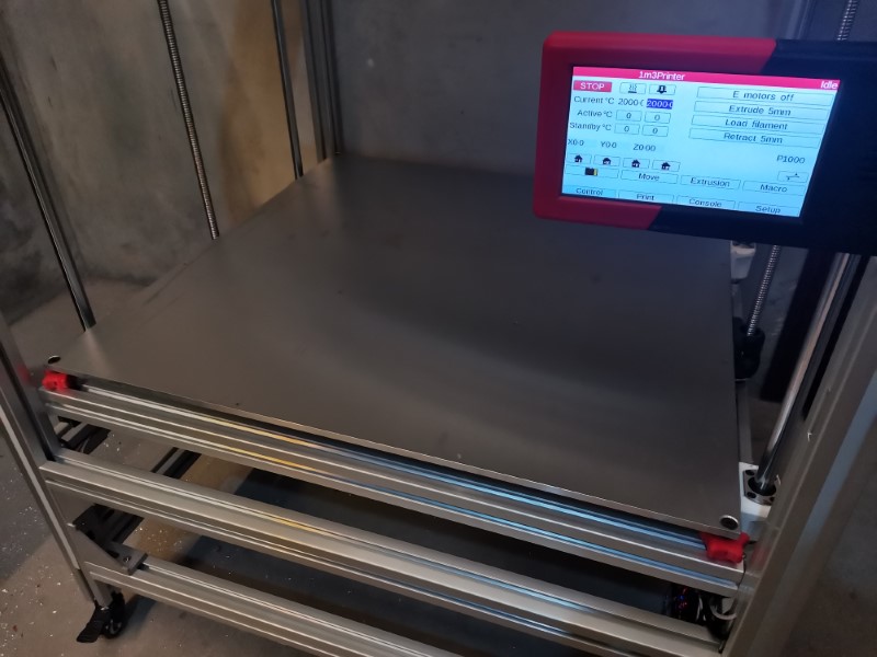
About heating time/first layer calibration, I think you’ll have a real head-ake. Though You might obtain a fast heat-up- which i doubt, considering the layers: silicone/air/alu(40kg)/air/glass, will be a lot of inertia. indication of thermal sensors(near silicone) would be meaningless for actual real time temperature of glass surface. I have seen a lot of thermal maps in printers bed surface and all have the borders green and middle yellow-red. What I mean it is a transient process and even if thermistors/bed reaches 60 degree in 4min, sabilisation will take 15-20 min on such a big bed and only after you can make a reliable bed leveling.
If I were what I’m not :grinning:, I would make a real-time ultrasonic bed level sensor. I would make first a pre-calibration with quite a dense grid (with ultrasonic, carriage does not need to stop for probing). After that, I would make a real time reading and correction for first layer, each 4-5 seconds (probe should be quite close to nozzle). Other than that you might have thermal bowing - 0.1mm/ 100mm leading to 0.4 mm in the middle of bed. This is not noticeable for human eye but does matter for first layer.
For the first layer adhesion, at least for non-good looking, large parts, I would reccomend perforated board - or kind of 3D UP-mini style board, fixed on all its edges. Together with raft, there is no match for print’s adhesion. Imagine in a 500mm diameter print thermal constriction generares forces of tens of kgf.
Good luck and hoping to see more.

3 Likes

Hello Mihai,

First of all, thanks a lot for taking the time to share your experience and suggestions, that’s much appreciated!

You mentionned some interesting and valid points:

-USB wires: I’m indeed not entirely sure that this will work yet. So far it seems like it does, but I have no idea about how long it will. So I guess the only way to know for sure will be to test. I can always revert back to something better later if it turns out it was a fail, so no biggie. One thing I tried to make sure of was that no effort should be put on the plugs at any give moment.
I hope it’ll work fine because it helps designing such nice electronics enclosures…

-Counterweights for the bed: thought about it, it’s not entirely ruled out yet so I might do that. Only issue being that my frame doesn’t make implementing such a system an easy task. I will see if the motors have enough power. It might be necessary because my motor drivers were already heating too much without the aluminum plate when I made some tests yesterday (but there was no active cooling on the board and it was super hot in the shop too)
The bed’s weight is my main concern right now,I’m not sure the Duet boad’s driver have enough power to deal with it, even though I’m using one driver per motor right now. Two things I still can try before such dramatic changes though: to go for a higher belt demultiplication , and/or for a planetary gearbox on the stepper motors.

-heating speed: we’ll see, but I think it won’t be a problem. My previous bed was able to heat in 30-45 minutes with a measly 150W of power… this one will have nearly 3000W so that should be more than enough. I’m quite confident on this.

-Heat sensor: I probably won’t use the ones installed on the heat pads. I’ll drill a hole in the aluminum plate and put at least one in there.

-Heat homogeneity: The plate will be between 10 and 15mm thick so that will help a lot to spread the heat. Most of the time I won’t make prints gigantic enough to reach the sides of the plate, so the most important part really will be the center. For really gigantic parts that will reach the sides, I’ll wait a bit more until the bed stabilizes. My previous heat bed was very much not uniformly heated but it worked okay anyway so I guess it’s not too much of an issue,

-Bed planeity while heating: I don’t think this should be a big concern, I’m doing a full bilinear bed leveling before any print, so there will be maybe a 1 minute delay between the probing operation and the beginning of the print, probably not enough to see some significant size variations on the plate. On my previous machine the build plate was really shitty compared to what this one will be, it was not very flat and poorly secured but it still worked fine. Never needed a raft or anything.

-Print adhesion: From all the things I’ve tried, glass with glue stick was by far the best. Actually, my concern is not bed adhesion but quite the opposite: how to remove a sticky print from a fragile mirror without exploding it…

Again, thanks a lot for your inputs, it’s nice to get some from people who experimented with such things!

1 Like

With pleasure Mr. Dui.
Just a wild guess, Z motors/drivers should cope. Only need to tweak them. Last solution should be another pulley ratio.
My Leapfrog has for Z a Nema 23 motor with pololu driver and it-s OK, well, not mentioning weight difference.
But I’m looking at SIEG X2 mill which is a heavy cast iron build with higher friction in its guides. In some CNC conversion kits the Z motor Nema 23 1.9Nm /3A direct drives the Z ball screw - mill head (not to mention belt reduction versions). Your 2 Z motors combined - I’m sure - exceed these specifications (except, maybe, voltage supplied). But a CNC Mill has much higher work load rating on Z during a job than a printer.

I’m following you as you are a real source of inspiration and I’m glad you share your work.
Good luck!

And - about Zmotors /drivers heating , as I thought further ;
In printers Z motors are used maybe only 5% to drive and the rest in break mode. Don’t you have posibility on your board to de-rate motor current in break mode? I think on some boards is possible.

One idea. You could add another frame on the left and right sides, giving you more space to fit a counter weight. Then you’d have to create a really dense volume to take at least a large fraction of the weight. I’m imagining something like weight lifting plates, but they would fit within those extra frames.

Definitely not there yet. Steppers are pretty strong when you move slow and your Z doesn’t have to break any speed records.

1 Like

Haven’t thought of that, thanks Jeffe. It’s doable, but I’d like to avoid it if possible because I’d like the machine to remain space efficient and also it will cost me more to build (that would be a lot of extrusions again).
If it ever comes to that, I could cast counterweights out of lead, I already did that for a project at work so it’s no biggie.

Good thing is, I tested a bit more yesterday and I think the power might be enough. My test wasn’t scientific at all since it consisted in me putting most of my weight on the bed while it was going up and down. I’ll make some real tests with real weights, but it seems like it has plenty of power and it did not overheat this time with the heatsinks and the centrifugal fan installed in the electronics box.

So during those past days I made a few things:
First, I made a new version of my enclosure. Looks very similar but it’s a bit bigger, it features 3 more usb ports on the side and I replaced the USBC with the HDMI port.

Printed it and installed the electronics, everything is wired now:

Installed the HDMI port on the print head side, it was real easy, took me less than 5 minutes. Super convenient. Then I connected both together with the 5 meters hdmi cable:

Works very well!
Heating works fine, temp sensor works fine, the fans blow much more than I would have expected which is awesome, the BL touch deploys and responds to commands… Great!

Also added a LED light under the print head, to better see the first layer:

It’s very bright, so that’s cool:


Almost everything is ready now electronics wise:

Only thing that sucks is that the HDMI cable I ordered is super thick, So I’ll search for a thinner one or at least easier to bend, but meanwhile I guess I’ll just strip the outside insulation and replace it wit a nylon sleeve or something. Right now it’s too stiff to allow the cable chains to work normally.

The HDMI seems to be a really good solution for now. Best of all: after wiring all that stuff I still have 5 or 6 wires available on it, so I’ll use them to pass the current to the extruder motor too. This way I’ll only have a single cable going to the carriage, nothing else!

So far so good, I still have to wire my endstops and the water cooling system. After that It will be time to tackle the bed.

7 Likes

Haven’t done much this weekend, but I found a lazy way to measure how much weight my Z motor will be able to lift.
So, basically, I’ve put a plank on the bed’s profiles, a scale, and then I’ve simply pressed on this scale to simulate a load.

The maximum I’ve seen before the motors started losing steps was a bit more than 50 kilos.
So that seems to be great news, the aluminum plate I plan on using will be somewhere between 20 and 30 kilos, plus a 3-4 kilo glass plate and some hardware (screws, nuts, washers, etc). Well within what the motors should be capable of. Also, with the added heatsinks and a fan blower, it seems like the motor drivers didn’t overheat this time.

I still hesitate on the aluminum bed plate thickness. One one hand, I’d like it to be at least 15 mm thick, but I can’t really think of any pragmatic advantage of having something thicker than 10 mm except for looks (would look beefier).
It would make sense to have a super strong plate if it wasn’t supported in the middle, but since the system I designed should allow me to physically adjust planeity on a 16 point grid I guess I shouldn’t need something that crazy.

So maybe the wisest choice would be to go for 10mm maximum, this way I save a bit of weight, which then can translate into higher Z axis accelerations.
Any thoughts guys?

1 Like

That is the amount it can lift while not moving, I would expect it to lose a little when it tries to move that behemoth plate. I hate to nay say without at least having math to back me up, but I worry that a 30kg plate with a 50kg max static load capacity is cutting it close.

That wasn’t static load, sorry if I wasn’t clear. I programmed the bed to go up and down continuously, while pulling my own weight on the scale. So it was moving and changing directions the whole time :slight_smile:

3 Likes

Ok, I came to my senses and ordered a 10 mm plate. Dimensions will be around 900 x 900 mm and it will weight close to 22 kg. 6061 Aluminum (7075 was 25% more expensive and it wouldn’t make much difference anyway)
Was much cheaper than I expected, “only” 75 bucks, including some basic machining (drilling the holes essentially).
So I’ll wait for it to arrive and hope it’ll work!

4 Likes

Small update: working on the X and Y endstops.

I’m using these micro switches, which I was already using on my previous MPCNC:
61IO8XIzvfL.SL1000

So I designed a small clamp system as well as an enclosure to protect it from dust. It includes a micro USB port on the right side so I can connect it easily to my motherboard:


Installed it on the machine:

8 Likes

I am going to name your machine the “BOx” as in Big Ox.

5 Likes

Haha, nice name, love it!

So, the BOx came home by itself for the first time yesterday, after I installed the second endstop:

The Duet2 board is really super convenient for tuning the firmware. No need to connect the usb since it can be done directly over the network on a nice browser interface, doesn’t take forever to compile, just hit save, the board restarts and a few seconds later you’re good to go again. That thing makes firmware edition a real walk in the park. Or maybe a football game on a sofa with beer and chips, because walking in a park can actually be exhausting and boring.

Only thing that needs a bit of getting used to is that the config files work using gcode, which is a bit less intuitive than tweaking the Marlin program using C. In Marlin, you can guess what stuff is doing, with the duet you have to google the gcode command to know what it’s doing. A bit intimidating at first, but you get used to it.
On the other end, that makes it less bloated and it looks cleaner.

Anyway, that’s an awesome board, still need to see how it handles an actual print but so far I’m impressed.

11 Likes

That thing will be sick!

1 Like

My printer is running on a duet board. Really like them.

2 Likes

Yeah so far I like it. But I have a problem with my BL touch, I cannot get it to work…
It seems to work fine at first glance:
-It does its self calibration at startup
-when I ask it to deploy or retracts, it obeys just fine
-No weird light or strange behavior

Problem is, it doesn’t detect any position change.
I can detect position change if I use a regular switch instead, so I don’t think the problem is coming from the duet board.

Tried everyting, even the resistor trick (which is not necessary on my board since it is a recent version), no luck.
It is to be noted that I tried to save a few bucks getting the “3Dtouch” instead of the BLtouch. So I’ve ordered the real deal this time, to see if it is any better. it’s 4 times more expensive, so it better worth the price.

Also, my aluminum plate should show up today or tomorrow,

1 Like

The only problem I’ve ever had with my bltouch that wasn’t my fault is it occasionally collects filament wisps and gets jammed. You have to be careful that you’re platform is low enough for the power on test, or it will error out. M280 P3 S160 becomes your friend then, that resets it.

2 Likes

Good news everyone, I received my aluminum plate, and it is awesome!

The plate has been CNC cut and drilled, so everything is where it should be. Moreover, and I really wasn’t expecting this, it is extremely flat! I was not able to measure any significant gap betwenn my spirit level and the plate, so I expect it to be within 0.1mm flat out of the box and possibly entirely perfect once I’ll adjust the 16 levelers! Also, I was afraid it would be a bit flimsy and bend easily in the midle with “only” 10mm, well it doesn’t, even though I have no support in the middle right now.
That is, for sure, much better than my old floor tile setup!

So anyway, I just installed the screws on the 4 corners so far. I had to tap and chamfer the 4 holes first. Then I drilled the bed’s frame, passed the screws and adjusted the knobs. Adjusting the knobs is easier than I thought, I was afraid it would be hard to turn by hand but it’s actually really easy.
Both knobs (red on top and black on the bottom) act together for moving up or down the platform and securing it firmly.

I will need to do that for the other 12 holes as well as to install the heating pads, so still a lot of work to be done, but so far I’m super happy with the result.

I had a bit of binding yesterday while testing the Z axis though, not sure what was the reason but one motor skipped steps. Last time it happened was because of a loose pulley, hopefully that’s just a simple mechanical issue like that. I still have a smaller pulley to install, to give it slightly more torque because I don’t really need speed on Z axis, what I need is acceleration.

Anyway, super happy with this aluminum plate, it makes the printer look massive and almost professional, love it. Much better than I thought It would be.


11 Likes

I am getting really excited to see the first giant part come off that thing!

5 Likes

4:1 scale core, with a tiny infill. Heck, even doing a vase print might take nearly a full Kg spool…

Alternately, the architectural model of your choice. Big Ben, Eiffel Tower, Sears Tower, Burj Al Arab, Tokyo Skytree, Oriental Pearl Tower, Petronas Twin Towers, etc., etc.

Oh! Think of the spacers you could print! A whole field of them at once!

2 Likes