Good day, everyone! I am a materials engineer and extremely into carbon fiber – these cool things that are 5x stronger than steel, but 2 times lighter than aluminum. Carbon fibers are utilized in the industry by combining them with resinous materials (plastics) and creating a rigid composite structure. I have worked with cutting-edge technologies for the advanced manufacturing of composite materials (carbon fiber + plastic) in Silicon Valley. However, through an unfortunate series of events, I needed to return to my country in the Philippines.
To continue developing technologies for composites manufacturing, I decided to build an MPCNC to be used as a low-cost robotic system for the automated placement and controlled deposition of carbon fiber in a process called pre-forming. This step controls the orientation and position of fiber reinforcements, a parameter that is essential in composites engineering. The mechanical performance of composites is anisotropic and is heavily influenced by the orientation of the fiber within the structure. By aligning the direction of fiber reinforcement along the local stress vectors, the mechanical performance of the part fabricated is optimized.
I am using the MPCNC to create preforms, aligning fibers according to the design, prior to subsequent processing to manufacture carbon fiber-reinforced plastic composites. I know this was not the intended function of an MPCNC, but it is an interesting venture and a budget-friendly one, so why not!
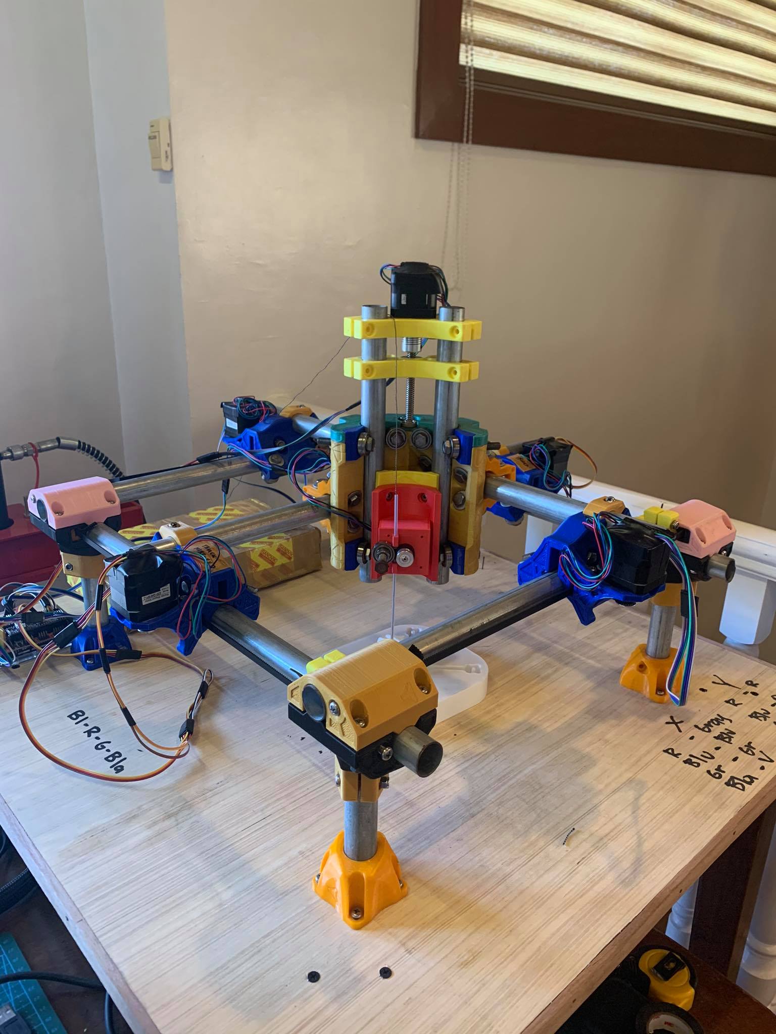
Here is the MPCNC Primo Machine that we have now (build and development to follow):
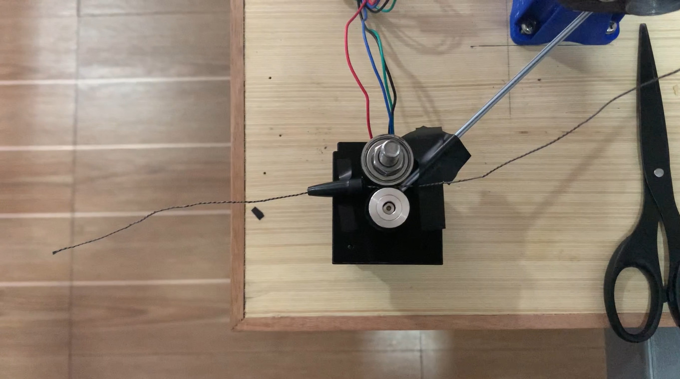
Here is a video of the primitive carbon fiber dispenser. The general idea is simple. Just two rollers (1 bearing, 1 motor-driven) and some guides. It’s like the 3D printer extruder but without the heating element. The dispenser would then be mounted on the Primo Core and function similarly to a 3D printer head.
Version 0 was just a carton box with some household objects.
Version 2 was also 3D printed and can be mounted onto the Core. We used the blank mount STL file that was available in the PRIMO build as a base design and incorporated our box design to it. We used a ballpen case as a filament guide.
Version 3. Adjusted the guide to minimize movement of the carbon fiber filament and achieve more precise placement. Checkout the carbon fiber spool at the back! The blue 3D printed mold was filled with carbon fiber material.
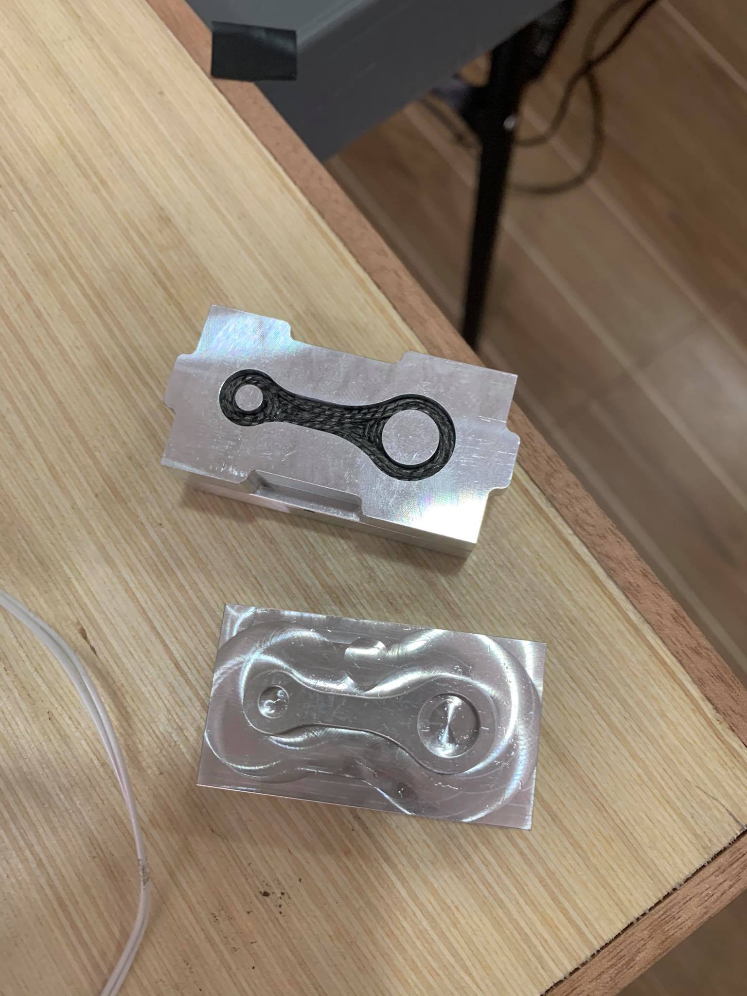
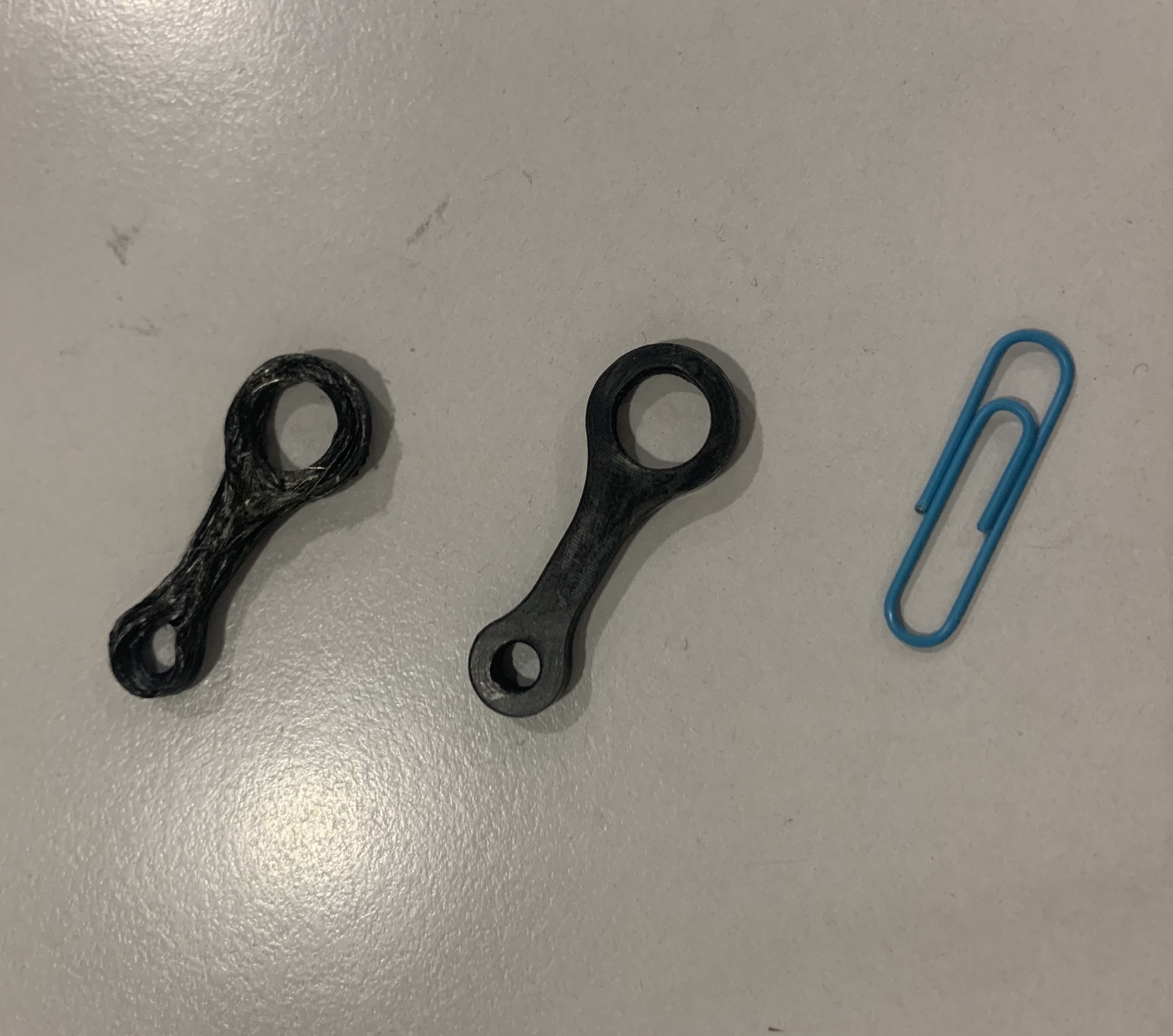
Some processing steps, et voila! This is the first part we have ever fabricated using our MPCNC-based Automated Fiber Placement system. The connector rod structures will be used for the mechanical testing of the part (coming soon). We will test it against CNC Machined aluminum and CNC Machined CF plate of the same structure.
(Left: under-processed. Middle: just right. Right: a paper clip for size reference)
You can notice the fiber filament going around the holes of the connector rod. This is the power of preforming. It allows you to control the fiber orientation according to how you anticipate the material will behave under stress. By having fiber reinforcements go around the hole instead of just having randomly oriented fibers/reinforcements, you strengthen the structure. (of course this is all in theory and still need to be validated!)
This is super impressive! Here I’m at the north pole trying to make fingerjoints, while others are using the MPCNC for cutting edge continous carbon fiber parts! This community is great What do fill the moulds that contain the fibers with, epoxy?
Hi! Greetings to you from the equatorial part of the world
It really is! This community is awesome!
We are using thermoplastic materials (plastics that melt as opposed to epoxies that just disintegrate under high temperatures). So what we do is we have small bits of thermoplastic material integrated into the filament, compress them inside the mold, raise the temp to melt range of the plastic components – subsequently resulting in plastic flow and wetting of fiber, and then cool them off resulting in a rigid structure. The reason is that this process is faster than waiting for epoxy-type of resin to cure.
Sounds like you know what you are doing, to put it modestly! Integrating the thermoplastics in the filament sounds like a great approach. Epoxy would be problematic in terms if keeping the strands in place as well.
Haha. Thanks! The MPCNC is an awesome robot to simply move around 2.5D space. Its ease of build and availability of materials allowed me to explore this idea. Hopefully, it materializes and we can get continuous carbon fiber composites in 3D structures! There are so many benefits to gain from lightweight and high-strength properties.
This is only the beginning and hopefully we’ll get more things done. I will continue to update you with the developments, and will try to post interesting parts that we’ve made and other experiments that we perform on these parts. I am also hoping to gain from the feedback of awesome folks back here, this is why I shared this project.
Lots of different plastics are actually really difficult to get to stick to anything, which is nice in some cases but a lot of times in industry it can cause issues when building composites (you want a touch of sticky in lots of situations to hold things together till cure/further processing).
@pceralde I am also curious what plastic is impregnated in the fiber.
LOL! Yep, just ask anyone who has tried to superglue broken plastic anything back together.
I would add that I’d also like to know what the 3D printed molds are made of, and does it undergo some post-print processing that makes mold release easier? I imagine that most of my prints would have a heck of a time releasing in the Z axis because of layer lines, for example.
Yeah, that is true. A friend who was working on robotics research suggested the MPCNC to me when I asked him what robotic system might be an easy way in for the application. It is a 3DOF robot and because of how it’s designed, it opens up a lot of opportunities for makers all around the world to create innovative robotic solutions.
We are using a variety of nylon plastics (PA12, PA6, PA66) and other thermoplastics (PPS, PEI) which have melting temperatures ranging from 180C to 300C. Just to clarify, the FDM-3D printed molds shown above were only used to test the pliability of the carbon fiber filament against features (curves, bends, etc.) of the cavity during the fiber placement process. The FDM-3D printed molds were not meant for production due to reasons you, along with others, have mentioned.
When it was time to make the part, we used other types of materials (this is still experimental and subject to optimization, but proof-of-concept shows it works) to avoid fusing together. We have done high temp resin and fabricated the mold using SLA printing. We have also used CNC machined aluminum. We are still exploring the best way (in terms of price) to make molds and (in terms of energy efficiency and uniformity) to raise the temperature. Here is a sample photo of a CNC machined aluminum filled with fiber:
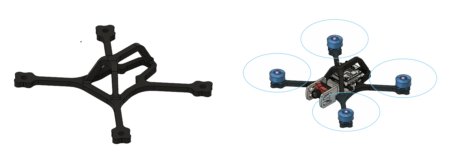
For CAM and tool path generation, we originally used a modified 3D printing profile and slicer. Like for the 2.5D connector rod above (2.5 basically means 2D object with extruded thickness), we simply used CURA with some mods. However, when we had to move into fully continuous 3D, we realized we cannot use the slicer algorithm for tool path generation anymore because it is not possible to move along XYZ plane simultaneously (the slicer extrudes layer-by-layer). So we developed one ourselves. Here is a sample photo of a continuous carbon fiber-reinforced drone frame we want to produce soon:
And you can imagine that if we upload this design on a slicer, the program will slice the 3D structure in XY plane which won’t allow us to place fibers along the beam longitudinal direction.
Yes, I totally agree! Wettability and adherence are two of the biggest compatibility issues in composites manufacturing.
We are using a variety of nylon plastics (PA12, PA6, PA66) and other thermoplastics (PPS, PEI) which have melting temperatures ranging from 180C to 300C. The carbon fiber filament was sized for these particular thermoplastics, hence, upon melting, these would easily flow into the interstices of the fibers.
hahaha! exactlyyy. Bonding/welding/sticking things together is really only as strong as the interfacial strength between the bonding surfaces.
So, to clarify, the FDM-3D printed molds shown above were only used to test the pliability of the carbon fiber filament against features (curves, bends, etc.) of the cavity during the fiber placement process. The FDM-3D printed molds were not meant for production due to reasons you, along with others, have mentioned.
When it was time to make the part, we used other types of materials (this is still experimental and subject to optimization, but proof-of-concept shows it works) to alleviate any microstructural abnormalities that persist (such as layer lines). We have done high temp resin and fabricated the mold using SLA printing. We have also used CNC machined aluminum. We are still exploring the best way (in terms of price) to make molds and (in terms of energy efficiency and uniformity) to raise the temperature. Here is a sample photo of a CNC machined aluminum filled with fiber:
")


 What do fill the moulds that contain the fibers with, epoxy?