Although I’m a perfectionist, I know this is not the machine to chase zero’s. For now I’m pretty happy. I’ll do some MDF cuts first to learn my machines limits.
1 Like
The results look good…tramming is certainly not the basis of the issue you originally posted. I suggest you rerun the test at a much slower cutting feedrate…say150mm/min and compare the results. You only need a couple of passes. If you see improvement, then the scalloping may be more about deflection than a tramming issue. Even with a shallow DOC, a router bit that big provides a lot of resistance.
1 Like
Yes I will try that… I’ve read on the ‘Shapeoko’ website that you can’t go below a certain chipload… if I go to 150mm/min, is that not too slow?
From the Shapeoko website:
Shapeoko chiploads guideline
For the minimum chipload value to avoid rubbing, there is a large consensus in the CNC community that a value of 0.001’’ (0.0254mm) is a good absolute lower limit guideline, at least for 1/4’’ endmills and larger. It may need to be lowered to 0.0005’’ for 1/8’’ and smaller endmills.
Also what about RPM? What I can remember when I used a router by hand is that the larger the bit is the faster (correction: slower) your RPM, I guess that applies here as well? What RPM do you suggest?
Also I might have solved the problem by making the machine more rigid, tightening bolts and screws. Before my gantry has a lot of room, now it doesn’t. Do you think the original problem is solved?
I’ve only been using the MPCNC for a year with no prior CNC experience, so take my suggestions in that context. As for chipload, the main issue is heat. I don’t believe you will damage your surfacing bit with a few shallow passes even at the slow feedrate I suggest. There is not enough time nor enough friction with the material for heat to be a problem.
Also what about RPM? What I can remember when I used a router by hand is that the larger the bit is the faster your RPM, I guess that applies here as well? What RPM do you suggest?
If you are concerned about chipload, the slower the rpm, the slower you can move the router and maintain a specific chipload. Of course you lose torque when you slow the rpm which can cause other problems. Loss of torque seems to especially be an issue with external speed controllers.
Shapeoko chiploads guideline
Chipload is still something I struggle with…not because the concept or the math is hard, but because there is such a huge variation in suggested chip loads plus it seems to be that much of the cutting using an MPCNC falls outside/below manufacturer recommended chiploads.
So take the Ryan’s recommended cutting recipe for every material and a recommended DW660 router. This recipe falls just inside the .0005 lower limit of Shapeoko’s chipload guidelines for 1/8" endmills and probably well below the recommended chipload from the endmill’s manufacturer. Single flute bits are not common. If I go to a common double flute bit I’ll have to double the feedrate to stay inside the recommendations. And If I go to a 1/4" bit with two flutes, I’ll have to have a minimum feedrate of 1500mm/s just to stay (barely) inside the recommended lower limit for 1/4" endmills. And for many of the endmills I’ve purchased, this lower limit is nowhere near the chipload suggested by the manufacturer of the endmill. I think a lot of cutting with the MPCNC is done well outside the manufacturer’s suggested chipload for specific endmills and perhaps below Shapeoko’s minimum chipload guidelines.
BTW: This video is the first place that speeds and feeds were explained to me in a way that I felt I got the concepts.
Do you think the original problem is solved?
Only you can tell, but slop in the machine can lead to the problems you show/describe.
My favorite hack for someone that didn’t have a 3D printer was to chuck in a wire that was bent to resemble the 3D printed one. It doesn’t have to be perfect, you just rotate the collet and see where the tip is low and where it is high.
I wouldn’t worry about chipload until you have a good starting place. Making dust instead of chips is fine. There are no chip police. Some materials can work harden, but if you’re just learning in some softer wood, it’s not a problem. When you get just a little experience with the machine it will be easier to spot issues and you can increase the chipload.
So I did another test in MDF, I think the result is pretty good.
The Z-axis looks more stable now, but still I notice a little bit of vibrantion, do you guys notice it also in the video?:


Info:
Single flute 6mm Carbide bit (it’s sharp when I put it in the collet it cut my finger).
10.000 RPM
DOC: 1mm
Cutting feedrate: 1000mm/min
Plunge rate: 333mm/min
It plunges in 90 degrees and I had a look in Fusion and I can get it to come in at a degrees.
The plunging doesn’t feel so good to me.
I think I understand what you mean, just put in a bendable steel wire?
But this one I can probably make:
Tramming
But is it necessary to tram the CNC at this point?
What I understand about chipload, is if you go to slow you dull your router bit.
Is the Shapeoko comparable to the MPCNC in terms of rigidness?
What you could try is move your router further up. I Had mine as low as you have yours, the thicker part touching the upper holding bracket, I moved it up later so the collet is only marginally lower than the Z rails. Might also help a bit with stability.
That is a good I dea, and raise the material…
No. The worry was that it was so far off that it was causing big bites. I don’t think you’re that far off.
I don’t know anything about the shapeoko.
It depends. You will need to replace your bits. They are consumables. They will make more cuts to remove the same amount of material, and they can get hotter, which can dull them faster, but only if you exceed the temperature where they get softer. It really isn’t something a beginner should worry about, IMO.
You have to see there are people who think things have to be perfect, and they end up spending $15k on a machine and follow all the rules. That’s fine. This is a different beast. This is about opening a door that was previously closed to the rest of us. If you can cnc something, then you’ve got a lot of projects that open up. You won’t be able to do it fastest or with the most precision. But you can do it.
The remaining chatter doesn’t look too bad. A finishing pass would clean that right up.
Good to hear, then I will leave it like this for now, I first want to do some projects.
It’s also a hobbiest oriented machine like the X-carve. But they cost around $2000,-
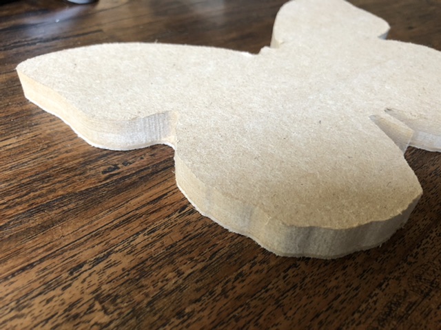
I’ll do some testing, what do you think about the Feeds & Speeds I used for the butterfly?
Yes exactly, I’m also on the Dutch cnczone forum. Sometimes it’s easier because I can write in Dutch. But the machine most of the guys at that forum have are more (semi) professional.
The first advice someone gave me is that my DOC was to low… it should be at least 9mm or so…
I’m pretty happy with my machine, I still can’t believe this budget machine can do great stuff.
Yes I should have done a finishing pass, I’ll do that next time.
Hey guys,
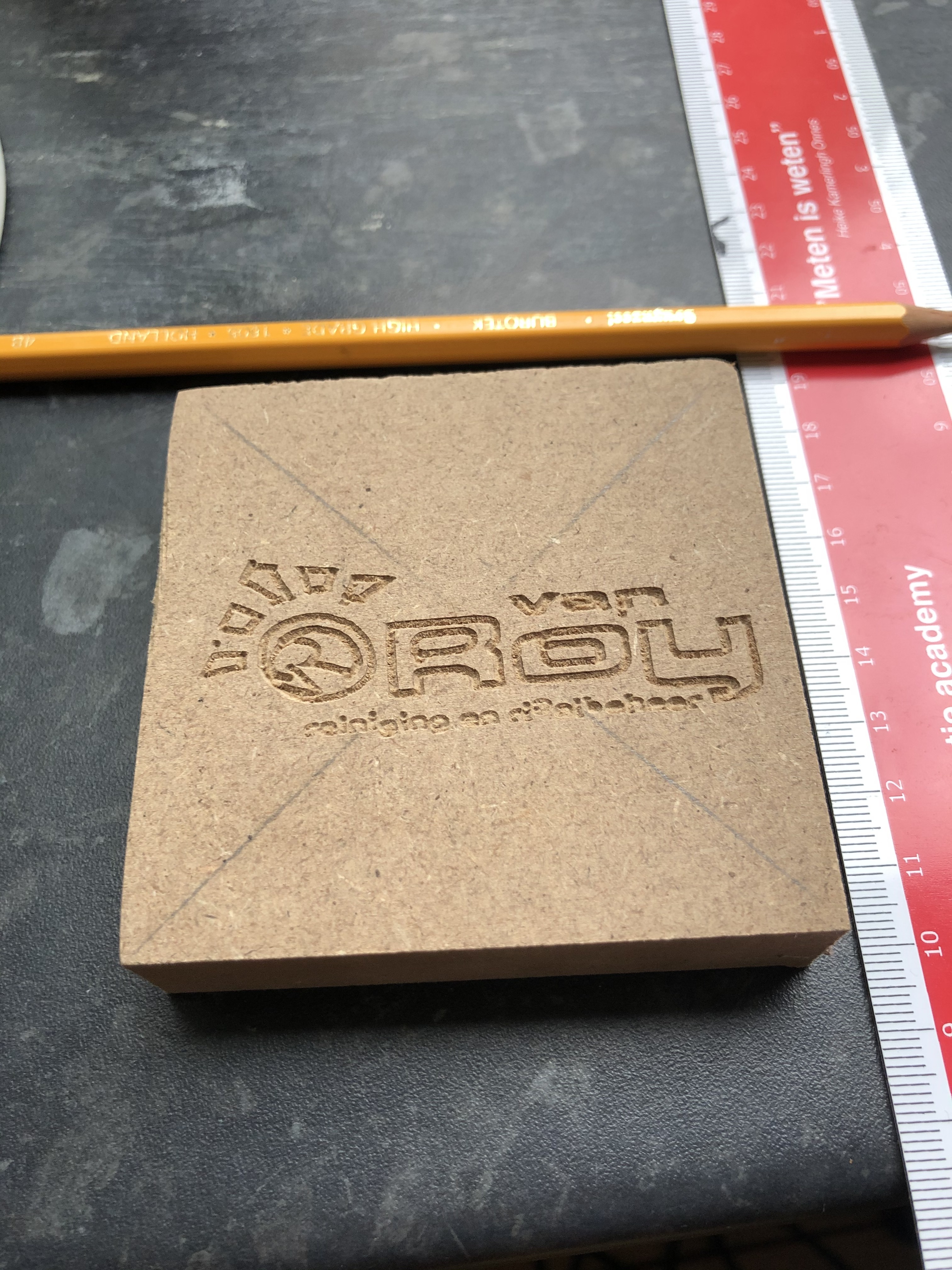
So someone asked me to do an engraving on some coasters so I was trying to do this on some MDF first. The result is pretty good, although it’s really small 80x80mm.
What I do notice is the circle isn’t a circle but more like an egg shape and not everything is straight (like the small letters). It’s a bit squased in the height/Y-axis, so the ratio between the x and y isn’t correct.
How can I improve this?
I did improve some things in Fusion 360 already.
I haven’t tried anything yet, but would it be better to set my microstepping a bit lower? I think it’s set to 1/32 microstepping now. Is 1/16 better for the MPCNC?
No. IMO, there isn’t any significant difference between 1/16 and 1/32.
This looks like a mechanical issue to me. Loose pulley, or loose belts, or a long Z or something.
I will check everything when I’m home… could it be that the bolts are too tight? I’ve tightened everything. The X and y axis doesn’t have to be really tight right?
And what about firmware settings of my stepper motors? I saw this thread:
https://forum.v1e.com/t/skr-v1-3-tmc5160-voltage-question/11988
Is this possible for the MKS Sbase board?
I have these stepper motors, 17HS19-2004S1
What kind of drivers do you have? Drv8825s have a little screw on the top to adjust the current.
Yes those drivers, but they are on the board I think… they can’t be taken off or something.
Maybe a jumper?
Ah. It probably has digipots. But I’m not familiar with that board.
Oké, so I should be looking in the firmware somewhere?
This is what I found on a google search:
https://www.modelbouwforum.nl/media/50095652_598514860601811_7200556317201661952_n.244408/full
Hey Jefe,
In my first thread you also mentioned digipot, I didn’t understand it at the time but I still don’t know what you meant by it. Could you have a look again please?
In ‘Configuration_adv.h’ is where I find the settings of digipots, btw how do I post the code like you do in the other thread?:
/**
-
@section stepper motor current
-
Some boards have a means of setting the stepper motor current via firmware.
-
The power on motor currents are set by:
-
PWM_MOTOR_CURRENT - used by MINIRAMBO & ULTIMAIN_2
-
known compatible chips: A4982 -
DIGIPOT_MOTOR_CURRENT - used by BQ_ZUM_MEGA_3D, RAMBO & SCOOVO_X9H
-
known compatible chips: AD5206 -
DAC_MOTOR_CURRENT_DEFAULT - used by PRINTRBOARD_REVF & RIGIDBOARD_V2
-
known compatible chips: MCP4728 -
DIGIPOT_I2C_MOTOR_CURRENTS - used by 5DPRINT, AZTEEG_X3_PRO, AZTEEG_X5_MINI_WIFI, MIGHTYBOARD_REVE
-
known compatible chips: MCP4451, MCP4018 -
Motor currents can also be set by M907 - M910 and by the LCD.
-
M907 - applies to all.
-
M908 - BQ_ZUM_MEGA_3D, RAMBO, PRINTRBOARD_REVF, RIGIDBOARD_V2 & SCOOVO_X9H
-
M909, M910 & LCD - only PRINTRBOARD_REVF & RIGIDBOARD_V2
*/
//#define PWM_MOTOR_CURRENT { 1300, 1300, 1250 } // Values in milliamps
#define DIGIPOT_MOTOR_CURRENT { 138,138,138,138,138 } // Values 0-255 (RAMBO 135 = ~0.75A, 185 = ~1A)
//#define DAC_MOTOR_CURRENT_DEFAULT { 70, 80, 90, 80 } // Default drive percent - X, Y, Z, E axis
// Use an I2C based DIGIPOT (e.g., Azteeg X3 Pro)
//#define DIGIPOT_I2C
#if ENABLED(DIGIPOT_I2C) && !defined(DIGIPOT_I2C_ADDRESS_A)
/**
-
Common slave addresses:
-
A (A shifted) B (B shifted) IC -
Smoothie 0x2C (0x58) 0x2D (0x5A) MCP4451
-
AZTEEG_X3_PRO 0x2C (0x58) 0x2E (0x5C) MCP4451
-
AZTEEG_X5_MINI 0x2C (0x58) 0x2E (0x5C) MCP4451
-
AZTEEG_X5_MINI_WIFI 0x58 0x5C MCP4451
-
MIGHTYBOARD_REVE 0x2F (0x5E) MCP4018
*/
#define DIGIPOT_I2C_ADDRESS_A 0x2C // unshifted slave address for first DIGIPOT
#define DIGIPOT_I2C_ADDRESS_B 0x2D // unshifted slave address for second DIGIPOT
#endif
//#define DIGIPOT_MCP4018 // Requires library from GitHub - stawel/SlowSoftI2CMaster
#define DIGIPOT_I2C_NUM_CHANNELS 8 // 5DPRINT: 4 AZTEEG_X3_PRO: 8 MKS SBASE: 5
// Actual motor currents in Amps. The number of entries must match DIGIPOT_I2C_NUM_CHANNELS.
// These correspond to the physical drivers, so be mindful if the order is changed.
#define DIGIPOT_I2C_MOTOR_CURRENTS { 1.0, 1.0, 1.0, 1.0, 1.0, 1.0, 1.0, 1.0 } // AZTEEG_X3_PRO
This is what I fine on this website:
https://git.x2d2.de/3D-Printing/Marlin-Firmware/blob/1dad6e754b1fc09e9018e663c7afc5da1794d0ae/config/examples/Mks/Sbase/Configuration_adv.h
So I think I have to alter this line:
#define DIGIPOT_I2C_MOTOR_CURRENTS { 1.0, 1.0, 1.0, 1.0, 1.0, 1.0, 1.0, 1.0 } // AZTEEG_X3_PRO
to something like:
#define DIGIPOT_I2C_MOTOR_CURRENTS { X.X, X.X, X.X, X.X, X.X } // MKS SBASE: 5
Fill in the Current of my stepper motors in the ‘X.X’