Multi-sided milling fixture

I am working toward 4-sided (or maybe more) milling.

The goal is a “kinematic” mount where each degree of freedom is constrained, but not over-constrained, so the mount doesn’t fight itself if the dimensions are not perfect.

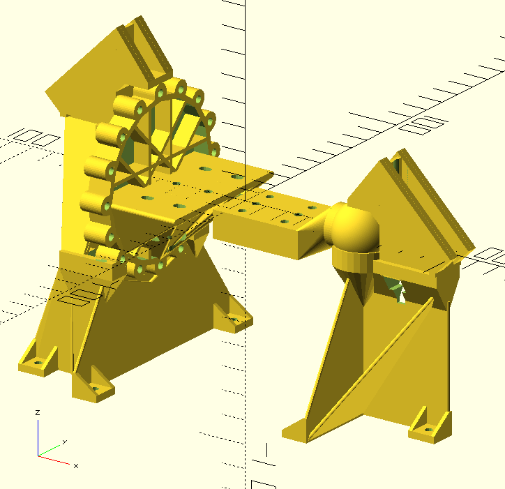
One end is a sphere in a spherical cup, so it constrains x, y, and z position of one end, but doesn’t attempt to constrain rotation in any axis.

The other end has N cylinders (in this case 8), two of which rest in cylindrical cups. This constrains the position in Y and Z, but not in X, while also constraining rotation about the X axis.

Together the two mounts hold the workpiece and allow removal and re-mounting with accurate re-positioning with rotation around the X axis.

Technically the mount is not kinematic. The system is over-constrained because the two cylindrical mounts could have an error in the distance between the cylinders, or the orientation of the cylinders might not be collinear with the workpiece, but those errors should be small or have minimal effect.

This setup can support 8 sided milling as it is now, and up to 20 sides is possible by making a new end piece with more cylinders.

I thought I would start with some two sided milling to get my feet wet. The flipping is shown here:

I’m still working through the steps to achieve multi-sided milling in Estlcam, which I’m pretty sure is not the easiest way, but so far it is doable with some hacks to trick Estlcam into giving the right Z height.

The fixture needs some better features for touching off the bit against for homing, and some areas could be a bit thicker, but the stiffness is already pretty decent.

7 Likes

That is really slick work. I can’t get the video to play. But it is probably something in my end. Very clever.

Cool idea and big props for scripting this contraption in openSCAD.
I’m also having trouble with the video though.

Ok, try again, I think the video is fixed now. Not sure how it got broken.

2 Likes

Cool contraption and lovely sense of details about constraining the right amount everywhere

But, I’m wondering how you can guarantee alignment between the (two, for now) faces?
When you flip the part in the mount, if the small spherical joint is not properly/perfectly centered on the piece (slightly off on the y or z axis), you would end up carving a little off from the other side wouldn’t you?

Would a self-centering jaw on the spherical end help wih this kind of stuff?
Or flipping the piece around the Y axis (exchanging the spherical and “disc” ends in the supports)? This one would at least guarantee the Y axis references the same edge of the workpiece (although you could still get some Z deviation)

The video is fixed for me. Very cool. I like the project too. Brass knuckle wooden spoon.

I am thinking about Fabien’s point. If the two ends are not cut square to each other. Or even if they are, but there is a curve in the board, flipping the board will result in an offset in +Y turning into an offset in -Y.

Maybe the slop in the 1/8th side mount will account for that (which explains why you were alternating tightening the two ends). The middle may still get out of whack, but there isn’t much you can do about that if the board is significantly warped.

1 Like

Right, these opportunities for misalignment is the reason for the kinematic-ish mount, and I tried to think these through but it’s possible I haven’t thought of something.

If you consider an imaginary line from the center of the octagon to the center of the sphere, this should define the axis of rotation. If the octagon is not perpendicular to this line, then that can produce issues theoretically because the octagon might “want” to square itself with the mount. Let’s consider that later and first imagine that the line perpendicular and centered on the octagon goes through the center of the ball.

The end of the workpiece where the ball attaches doesn’t have to be square to the axis of rotation. That’s part of the reason it’s a ball and not a cylinder. Wherever the ball ends up defines one end of the axis of rotation.

The length of the workpiece is also one of the places where the mount (on the octagon side) accommodates some error. As long as the ball side is tightened first, the octagon side can move a little bit axially. The length needs to be accurate to within a couple mm, but that is okay because I’m able to cut to within a couple mm.

Now if the end of the workpiece on the octagon side is slightly out of square, so the axis (between the center of the octagon and the center of the sphere) is not perpendicular to the plane of the octagon, then the cylinders on the octagon will not be parallel to the mounts that they sit in. This can put a torque on the workpiece, but since the cylinders are relatively short, the hope is that it would be relatively minor. If the octagon side is tightened first, then it could lock it at a bit of an angle, which is probably not a big deal since the ball end will push it into position, but where it does matter is on the X axis length. If the octagon end is locked and the ball is out of position axially, then it will fight itself when both sides are tightened. This is why the ball end should be tightened first.

Now as for how the mount is aligned with the sides of the workpiece, that is not controlled accurately. This could be a tree branch that is irregular on all sides except the ends, or if it is a perfectly square workpiece that’s been jointed and planed on all four sides, it can still be mounted wonky. The current system is uncontrolled.

Currently the ball end and the octagon are mounted flat to the ends, but a modified version of those end mounts could impose some alignment with the surfaces of the workpiece. One thing I am already considering is if the workpiece is flat and relatively thin, an “L” shape on each end could mount to the face of the workpiece on both ends, instead of mounting on the end. Or if it had a “U” shape with thickness to match the workpiece, then a 1/2 inch plank could be mounted centered.

That is messing with my head…I feel like as long as you homed the bit to the centerline, in all three axis (you could use a defined point with offsets) it would not be able to cut incorrectly? The mounting system seems to not over constrain (maybe a tiny bit on the hex end but that could be spheres locked into a cylindrical slot instead of cylinder on cylinder)?

Right? If you mount something in a lathe off kilter and cut it with a tool it leaves a perfect circle with a cooked clamped surface.

This feels like one of those brain-teasers. I am twirling ones off axis to think about it.

1 Like

I believe so. Or that’s the idea. The axis has to be aligned physically with the machine and after that it should remain on axis with predictable increments of rotation.

If the workpiece has its own axis (like a cylindrical object) or some datum that maters, then it can be mounted improperly and there would need to be other features in the mounting points in order to reference the existing features on the part.

I could potentially use a “sphere in slot” on one side and “sphere on flat surface” on the other side and it would be more tolerant to being out of square on the octagon side, while still constraining y and z location and rotation about x.

1 Like

It is a lot easier to mill one side flat, than trying to get two sides parallel (especially if they are 18" apart). Referencing one face for both ends might be better. But you still have the issue with the octagon face not being perpendicular to the axis from the octogon to the ball. If I was trying to mill (jointer, planer, table saw) a piece, I would joint one long edge (probably the 1.5" side) and then put that securely against the fence on my table saw sled and cut the two ends perpendicular to that jointed edge. The accuracy of the table saw and sled would determine the accuracy of the flip. But they are pretty close on my TS. I think that is as close as I can get to making those two ends be perfectly parallel and roughly perpendicular to the main axis of the wood.

In the end, there is always error. So the question is how much from these “easier to find” errors vs. stuff like warping wood or whatever.

2 Likes

In the world of Woodturning you’d use an indexing plate. A series of holes around a disk at specified intervals. Fix the disk to the work in this case. A pin goes through a hole in the plate and the support fixture to hold the work steady. The opposite end just needs a standard tail stock for support. With a properly squared CNC, making the disk is easy. You virtually have that with the 8 cylinders already.

@jamiek I don’t know how I missed this. Pretty cool! Any updates on your progress or did you abandon the concept? I’d also like to see the finished spoon. :grin:

I somehow missed this topic. This is cool Jamie. It reminds me of the 3-side and 4-sided jigs used by Dennis van Hoof for his Shapeoko which has always blow me away:

1 Like

The finished spoon was not a success because somewhere along the line my offsets were off and it was very thin.

I don’t think I’ll be doing much more with this concept, and a motor-driven rotary axis is probably where I would put my effort instead. I have a surprisingly low tolerance for mucking with the workpiece or tool during a job. And in addition, this is motivated more as an exploration of an idea rather than the need to get something done, and the exploration has gotten far enough to satisfy me.

I just post the files here on Printables in case anyone wants to explore with this further. It looks like I did add the radial mount instead of axial mount, but I don’t think I got to the point of printing it to try it:

4 Likes

I strolled in on this a bit late… I like the thought process going in to this. Too bad it didn’t turn out to be very feasible in reality. Sometimes I wonder if it wouldn’t all be so much simpler if we just had a solid robotic milling arm for diy. Alas, I’m still not even 1/4 the way up the learning ladder with just 4 axis. Wishing you luck on the motorized method!