Hello there!
I’m not sure if this is the right category, because my build is neither Lowrider or MPCNC. I designed myself everything, and thought I share it on this forum. I used design solutions from V1 engineering and I want to give credit where is due. I used the guide tubes idea, the ball bearing tracks, also the electronics advise and firmware from this site.
See a few pictures below
Maybe off topic is better, but I like it. I see a little bit of at least 4 or 5 V1-inspired builds I’ve noted on thingiverse. Influence, I mean, or at least similar thinking. Your parts and implementation are definitely unique.
Now, go get it dirty and post some video!
Thank you!
In a few words I will describe some maybe unique features:
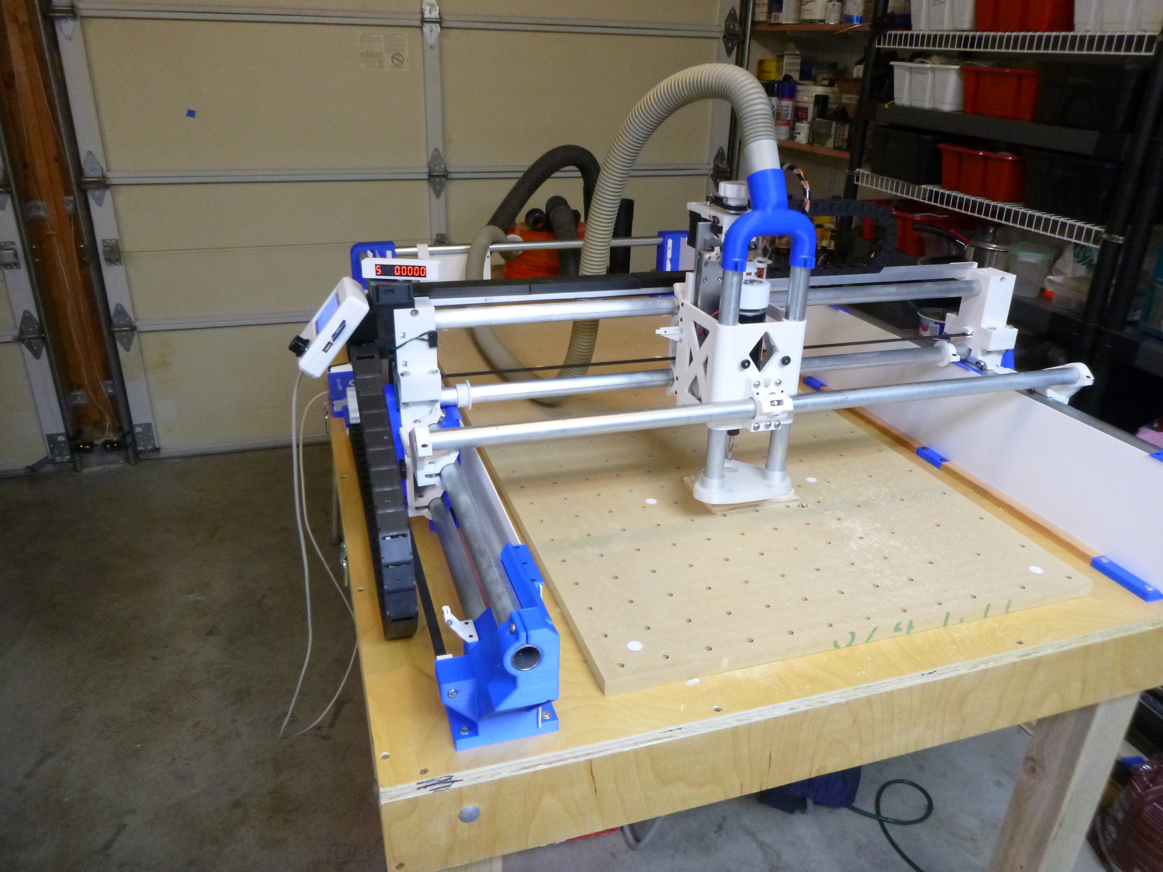
The Y axis is riding on 2 parallel bars, supported in multiple places.
The X axis riding on 3 bars for increased rigidity (I intend to cut aluminum too).
The spindle is controllable in the program, using the FAN_0 port, printed a new cooling fan for the motor with 2 magnets incorporated for a hall sensor for speed display
Motor speed display, but not as an active feedback for the controller.
The Y axis motors are mechanically synchronized with a bar thru the lower X axis tube
Integrated dust collection with adjustable height from the workpiece, independent from Z axis movement
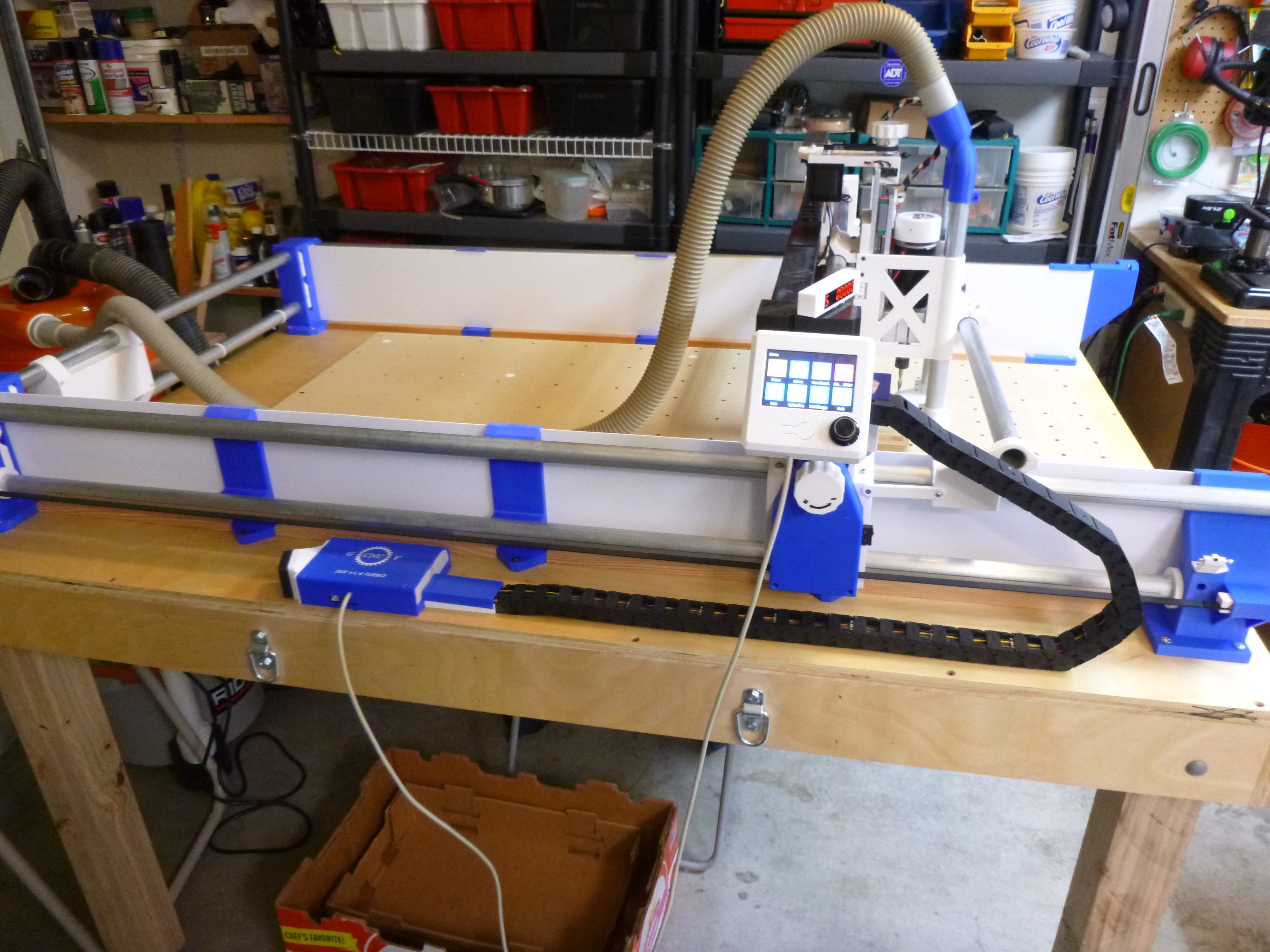
Using exclusively the TFT 35 to control the machine as a pendant, or docked on the carriage
The white protector side panels in the pictures are in channels, easy to slide them out for cleaning.
At this point I made only some test cuts to prove my post processor also check the rigidity.
More to come.
I forgot to mention the travels: X axis 620mm Y axis 1240mm Z axis 100mm. (The goal was to fit a full sheet of 2x4)
Looks like it will work well. I like to see any printed robot. This one has a lot of neat tricks in it.
The MPCNC and LR have stepped motors that just always move in lock step. I am not criticizing, because I am sitting on my couch and this is a lot of excellent work. But I am curious (and trying to be a little helpful). Why not just control them to sync up electronically?
Hi Jeff!
I’m a retired mechanical design engineer, and just believe that sometimes a simple mechanical solution is more reliable than the electronic ones. In this case I have only one limit switch on each axis, and if I move anything with the system powered down will not lose the alignment.
I have a lot more features not described yet, but if interested I can go in details. Also some of the issues I found with the off shelf components.
Sorry, I did not answered your question. The DRO displays the spindle RPM as described above
George
That is a pretty good reason. The V1 machines move pretty freely with the system powered down, so they need some way to make sure that they’re aligned when the system is powered up. Dual endstops does a pretty good job of that, IMO, or power-on proceedures where you hold the gantry against stops to ensure that it powers on square, but both can be subject to human error, and there is valu in a machine that does not lose square when powered off.