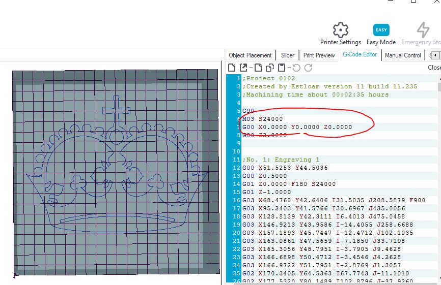
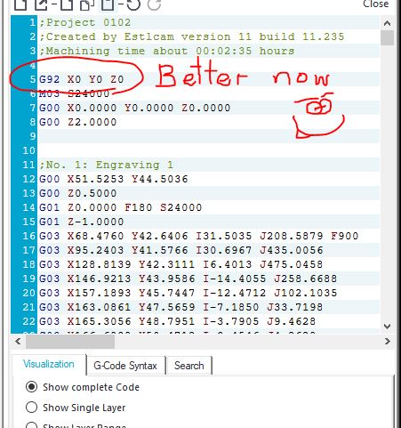
I think it is setting to 0,0,0, before printing (as per image) … but before this it moves up in Z axis first ( 30cm or more up) Could it be that it’s going to a home position first ?
The circled line is a move command telling the machine to move the tool to what the machine thinks (really, “knows”) is the tool’s 0,0,0 coordinate, also known as the origin. Unless you change this, it is the location the tool was at when the machine was powered on. G00 (or sometimes just G0) is a straight line travel move. G01 (or sometimes G1) is a straight line move while cutting. Travel moves generally go at a higher feedrate (faster) since there’s no need to account for the drag of the cutter in the material.
G92 is (one of) the command(s) that can be used to reset the coordinate system. Move the tool to the desired start point and issue G92 X0 Y0 Z0 to reset the origin so that the current position is known to be 0,0,0.
If end stops are installed, the homing routine will also reset the coordinate origin for the axes included in the homing routine. You don’t need end stops, G92 can be used to set the current machine position to any arbitrary coordinate values.
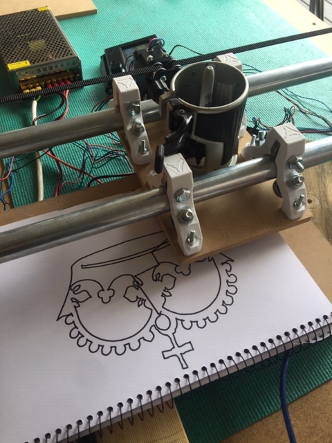
I had some difficulty getting the Sharpie pen to stay in place so I held it down from time to time… so the retraction lines are still there since I was pushing on the pen… Not a bad effort for a newbie I say.
I sure I hope I can get some cuts done before Christmas as I’d love to build my little boys a few toys.
In all honestly… it feels damn good to reach this milestone… damn good
Congrats it looks pretty good. There’s some wobble in it but that sounds like the pen mounting. It is a big milestone, next comes brave pants for the loud button.
Regarding the car - yeah I decided to downsize ( keeping in tune with global warming and all ) It was that or ride a horse & as you can see grass is scarce.
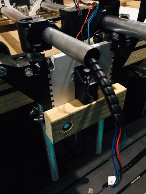
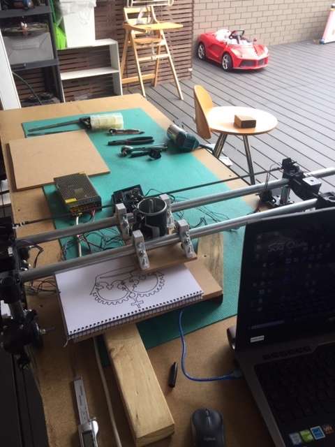
I’m busy threading each stepper motor cable through X-Axis tubes. I extended each wire and soldered them and am now wrapping them in spiral cable protectors.
Am wondering where best to mount the power supply and driver board ? I’m thinking of having all sit on the X-axis tube ends a there’s approx. 10cm over hang. Hope this is OK … not too heavy or offset the motion ?
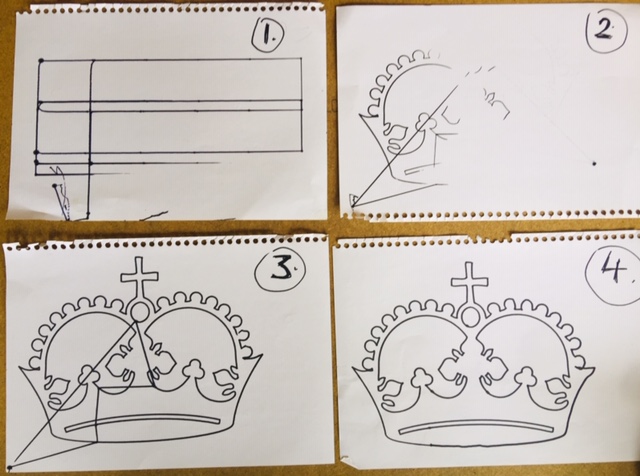
Here’s several iterations of the CROWN using a sharpie.
Starting from my first movement in X / Y manually to adjusting the Z to final crown image.
Worth noting, my table surface is badly out in terms of the Z height on one side being a full 1cm lower. That’s massive !! so to compensate till I purchase a nice piece of board I’ve adjusted the Z screw on one side. I know not the best but it’ll suffice for now
I picked the crappy board up off the street (it’s just for my inital build). Later I’ll swap it out & use that piece for sound proofing.
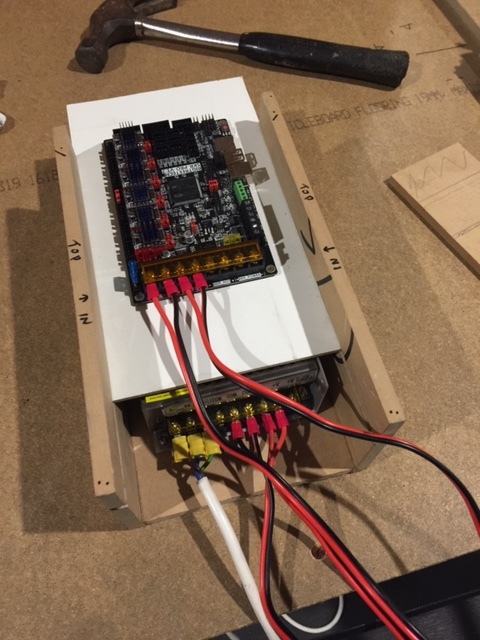
Started building the Controller / Power Box today.
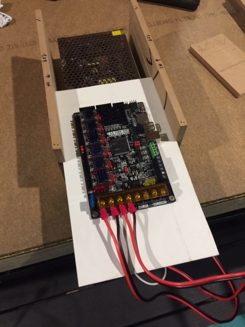
I decided to add a sliding plate that the driver board will be mounted on for easy access.
The power supply I’m not overly worried about, as it sits under the driver board.
I made sure there’s enough room for air flow while keeping the top half fully sealed to avoid dust.
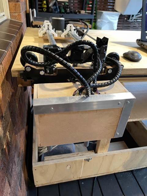
The box will be mounted to a block of wood attached to the Y-Plate (as per image below)
I notice a USB port on the side of the TFT screen. Does this allow me to disconnect from the driver board and control the machine via my laptop through the TFT screen ?
Next up:
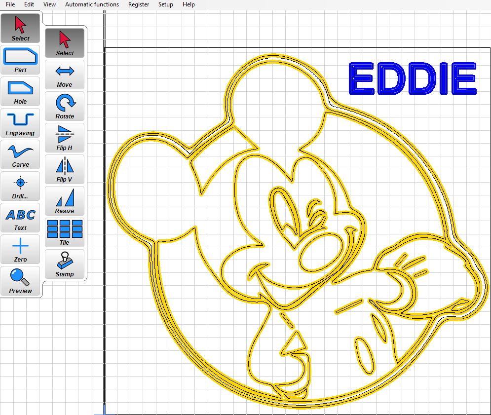
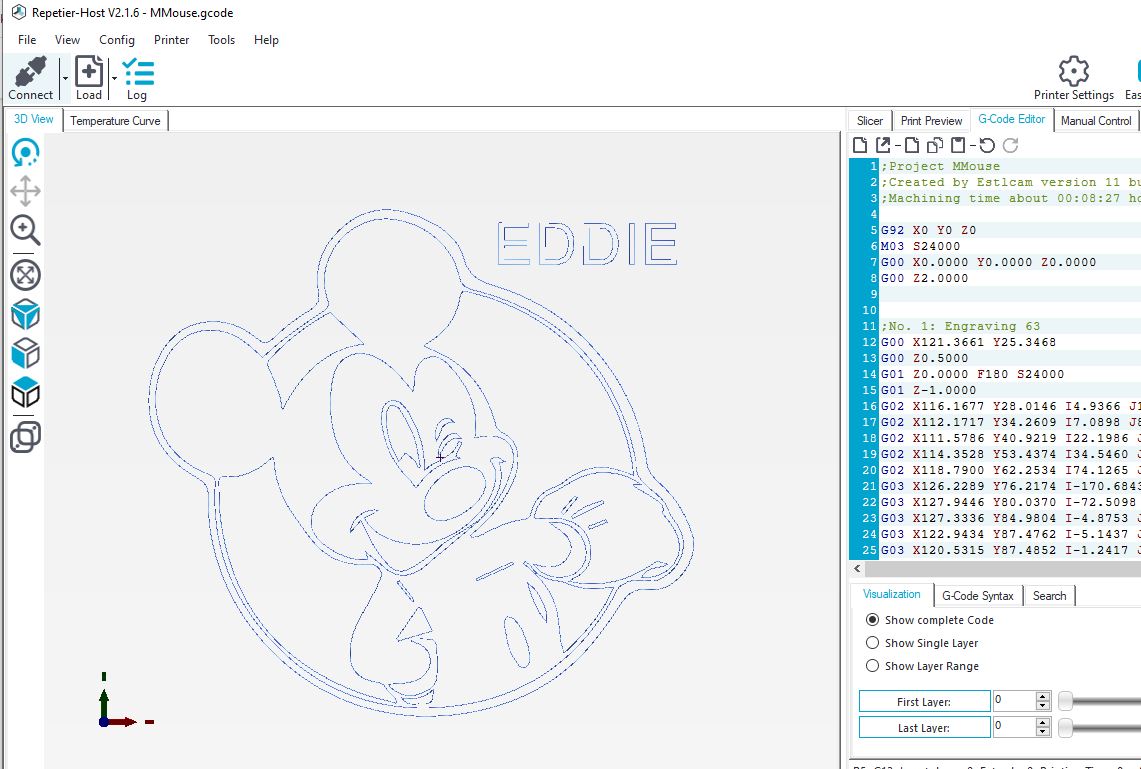
I’ll try my hand engraving -
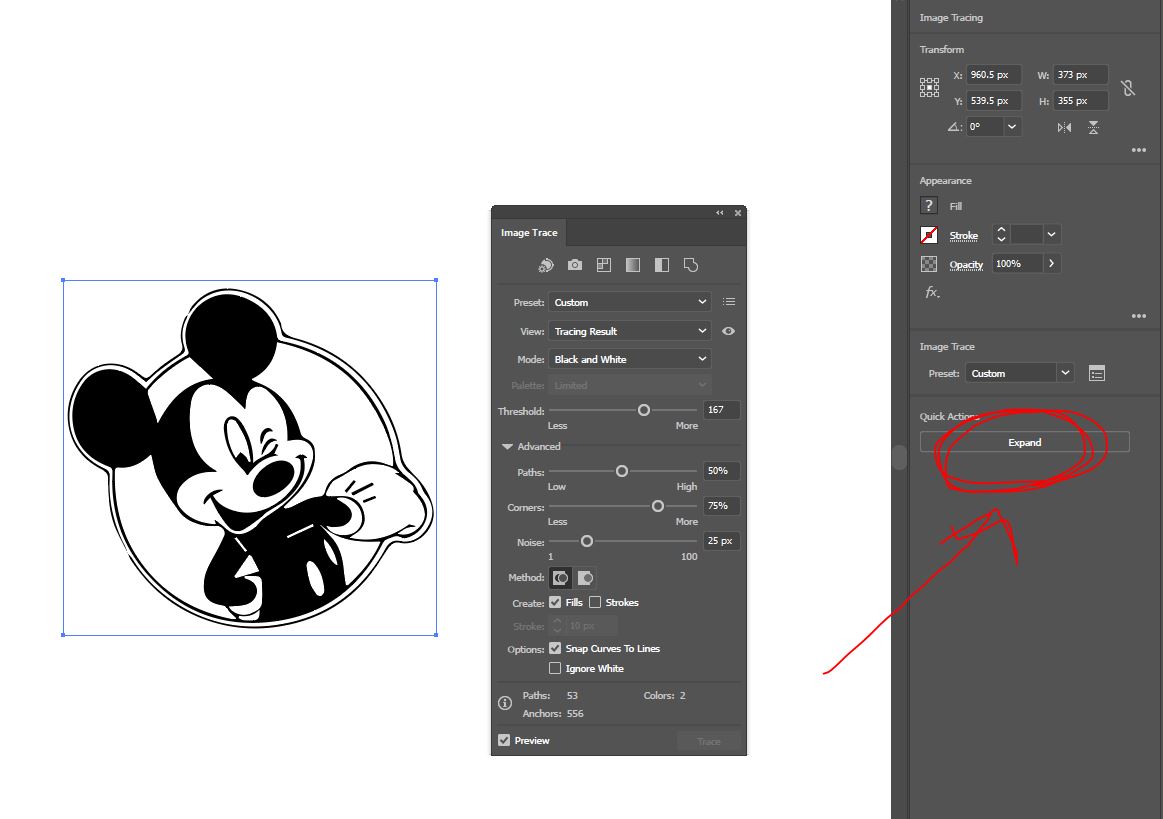
I’ve taken a vector illustration of Mickey Mouse out of Adobe Illustrator & into Estlcam.
Illustrator Tip: I started with WINDOW >> IMAGE TRACE & then had to select " EXPAND " which allowed me to select the path.
I then saved this out as a DXF file.
 test 01")
 That’s massive !! so to compensate till I purchase a nice piece of board I’ve adjusted the Z screw on one side. I know not the best but it’ll suffice for now