I finally got around to putting together a LowRider “Lathe” attachment that I’ve been pondering for some time. This was essentially a “I wonder if I can do this” type of thing.
So, it DOES work. It doesn’t work great, but I think it only needs minor tweaks to make it a little more robust. Securing the stock is the main area of concern, but after the first test, I’m pretty sure of what I need to do to remedy the shortcomings.
On with the pics…
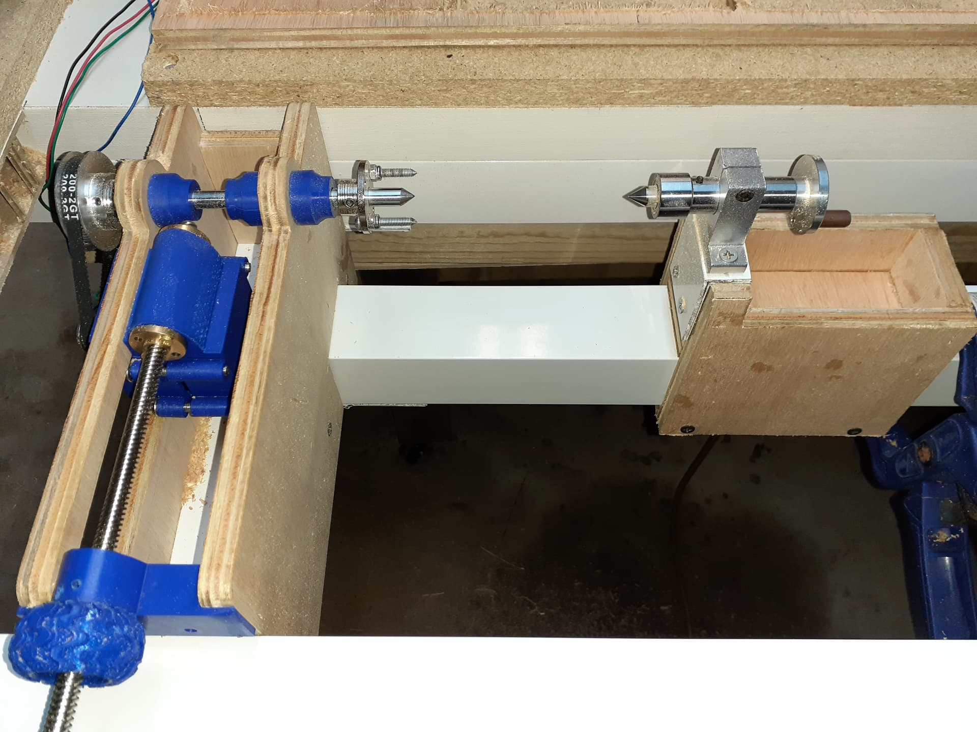
This is the headstock side. I have the stepper turning a larger timing gear which is mounted on an 8mm rod. This rod is held in the wooden frame with thrust bearings (thank you, niget2002) which are held in place by collars (thank you, vicious1)
These bearings and collars are covered by the blue dust caps to keep sawdust out of the bearings.
The stepper can be adjusted toward or away from the rod via the lead screw. This will allow for timing gears of various diameter and belts of various lengths. I simply unplug the LR Y motors from my board and plug in the stepper from the lathe. Then I park the LR directly over the stock in the lathe and secure it in place.
Thrust bearings take care of the axial load, but the rod still has a little play radially. I will be adding more (different) bearings to handle radial play.
Entire assembly needs to be supported better so as to remain perfectly solid when stock is loaded.
I think a little piece of aluminum angle secured to the table to the left of the frame will take care of that.
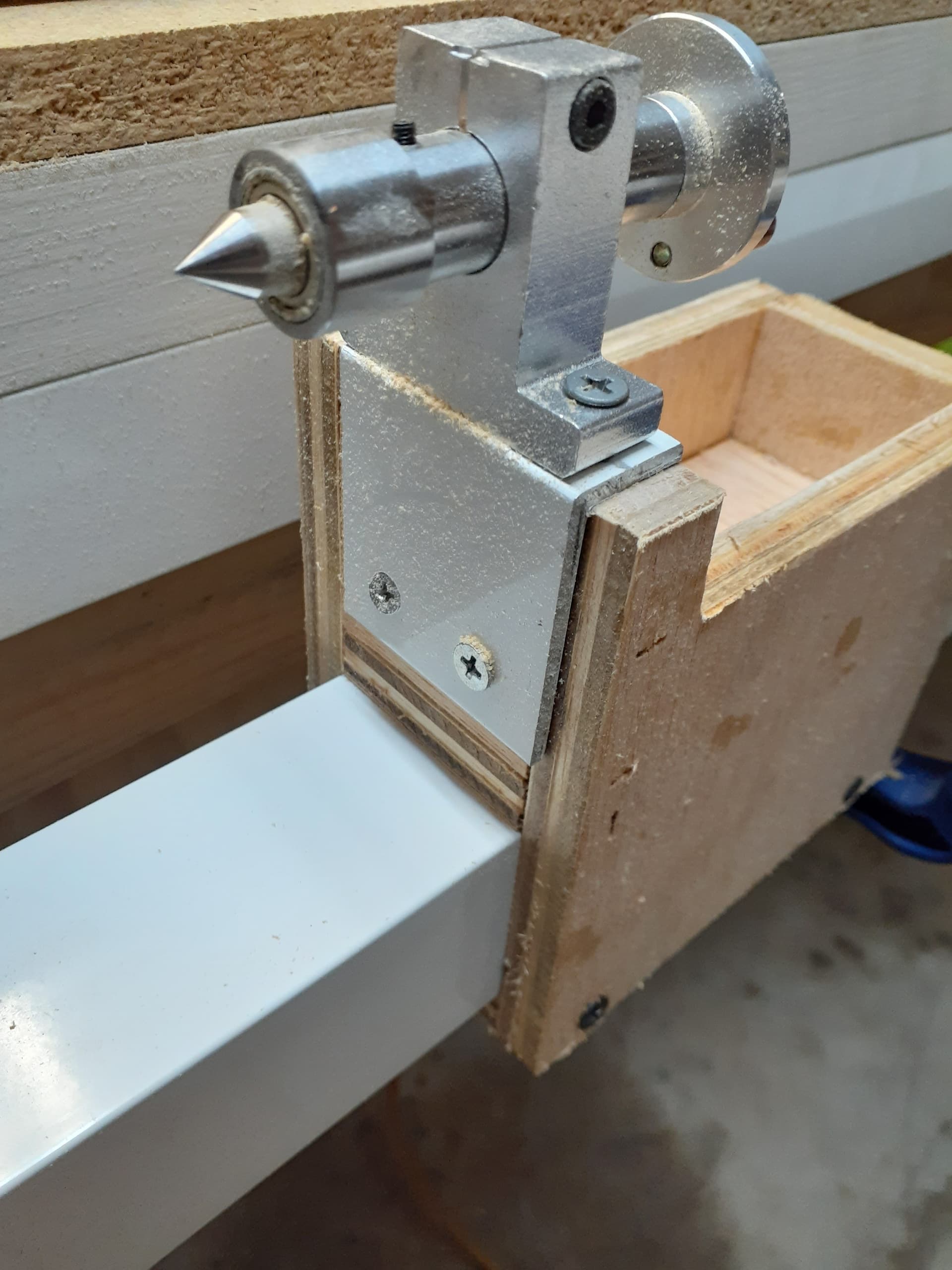
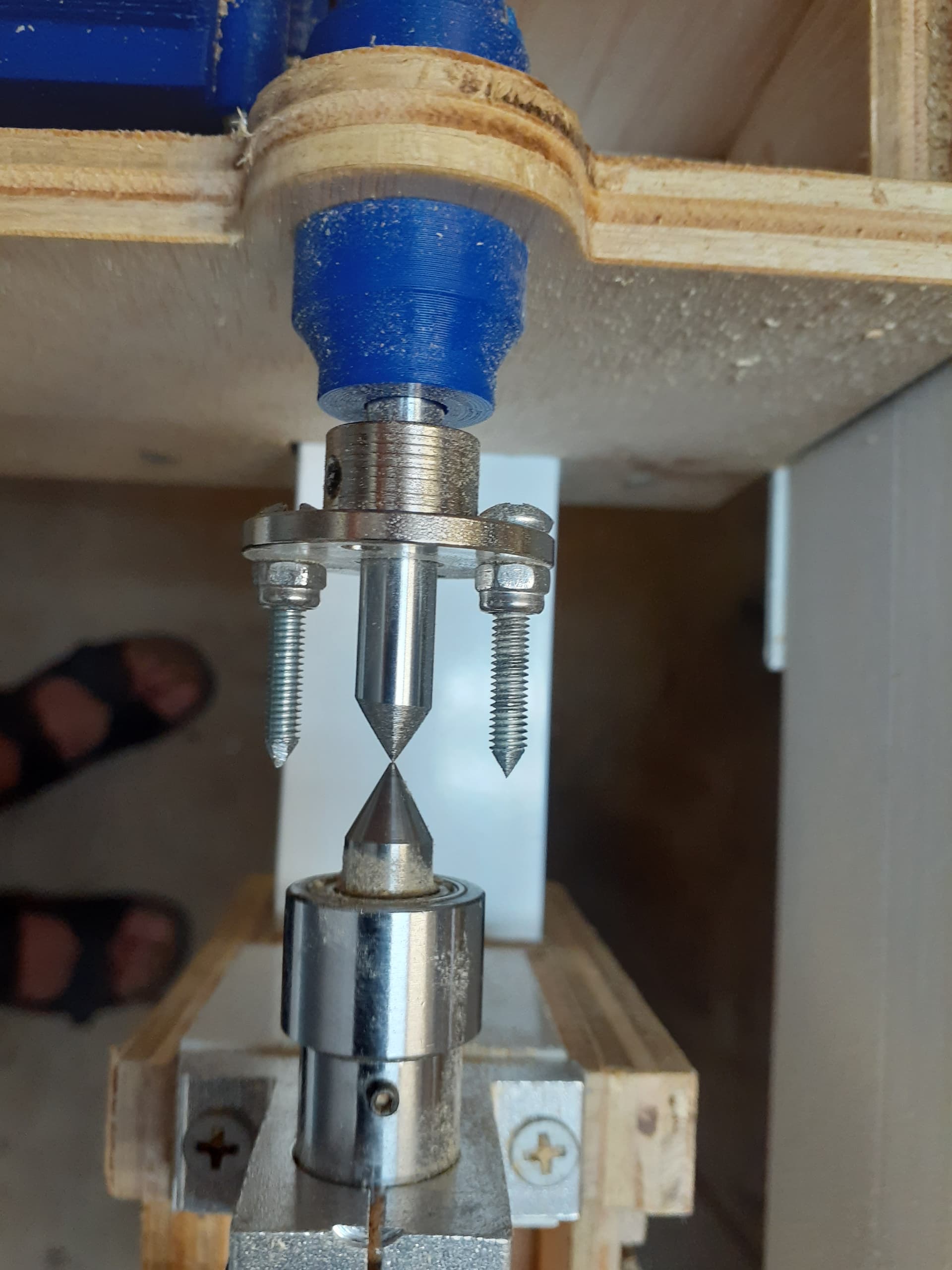
The pointy bits securing the stock are completely inadequate. Will probably eliminate the sharpened bolts, secure the flange directly to the stock and secure the flange to the rod.
No real problems with this. It slides on 2" aluminum extrusion that was meant to build screen rooms.
(My entire LR table top is constructed from this). I just need to find some sort of clamp to secure it in place when I’ve mounted the stock. Some sort of hold-down clamp should work.
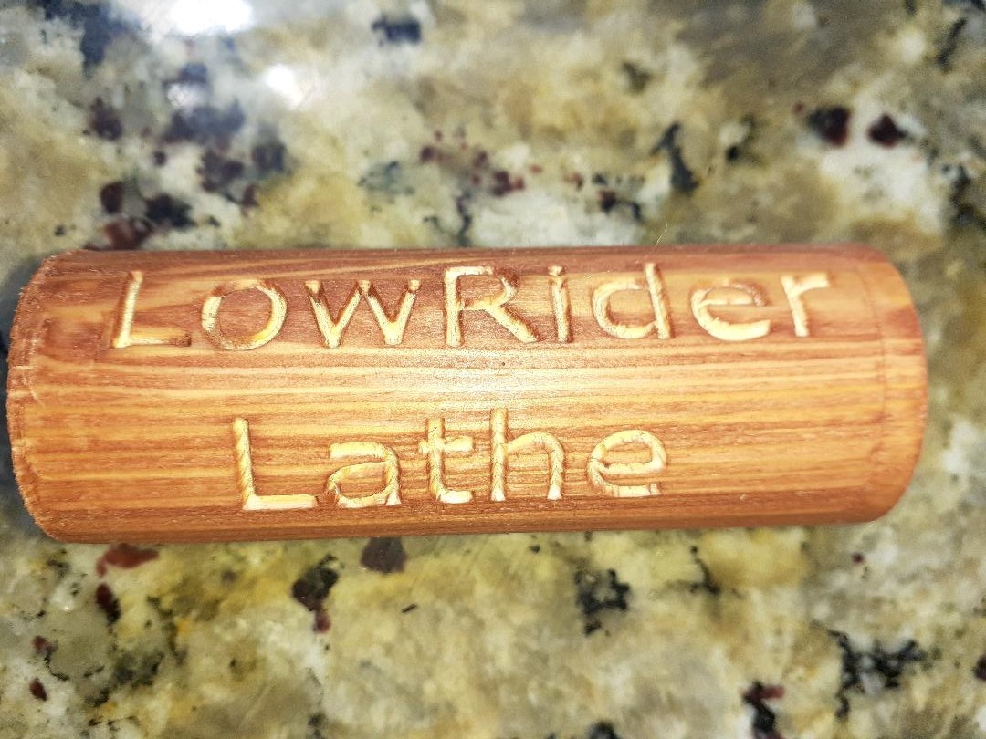
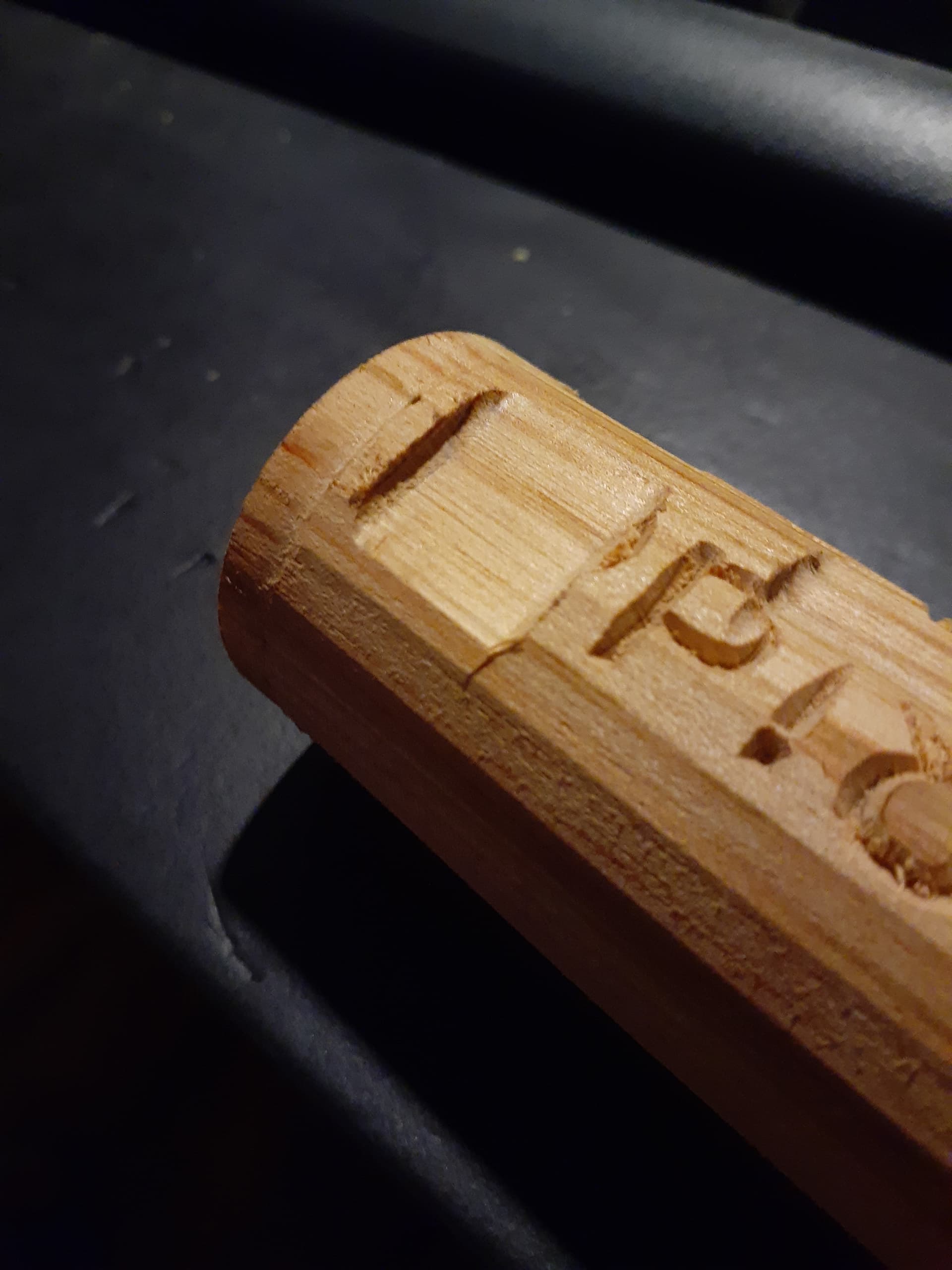
It started out as flat-sided lumber. We cut it down to a cylinder on the lathe, then did the little carve.
I dabbed on some stain AFTER the cut to better emphasize the carve, but got some of the stain got into the carve. It’s actually a pretty clean carve.
I have a video of the first cut, but I have to clear it with Ryan before posting. It may show a bit too much of the LR3.
There is a lot I love about this idea and design. Very cool. I happen to have a big opening at one end of my CNC table. This project, or something similar, may be on my future project list.
Something I would very much like to be able to do is “switch” motor control from the LR to the Lathe without physically unplugging the Y stepper wiring from the board. I’m worried about wearing out or damaging connectors.
I’d like to maybe have an extension coming from the board into a “switch”, possibly mounted on the board box, that would allow me to choose to route control to the LR or to the Lathe. The LR wiring would always stay in place, and I could plug the lathe into the switch only when using it.
I have had no luck locating such a physical switch.
I’m sure someone on the forum could come up with a way to do this using alternative outputs from the board and firmware, but that is WAY outside my sphere of knowledge.
You can find “4 pole double throw” (4pdt) switches that have 12 connections (4 to the driver, 4 to the Y, 4 to the lathe). They will be controlled by one switch. A couple things to keep in mind:
The load in most of our machines, to our motors is about 1A at 12VAC. If you have a 24v supply, it would be 24VAC. The switch doesn’t have to match, but make sure it can handle more than that. Most should. Switches made for automotive or boat applications are probably best. The first result I see at McMaster-Carr is 125VAC@15A. That is probably huge.
Don’t ever flip that switch while the driver has power. It is probably safe to swap it if the driver is disabled. But to be safe, I would mount it where I can’t bump it, and only swap it when the board in unpowered.
2pdt switches are more common (6 terminals). Two of those would work fine too.
I saw some of the rotary ones, but they looked HUGE. Didn’t know if they would work for this application. I’m familiar with residential wiring, but don’t know much about circuit boards.
So after all this work to turn flat things into round things, my daughter and I spent a good part of our day figuring out how to cut a flat surface on the lathe.
We had a few theories, did a bunch of geometry (had to dig deep into the archives for that) and after a few attempts I think we figured it out.
It turned out to be some great father/daughter time. It’s been a fun project for us.
That is a big one. The switch I mean :). Picked up a 4PDT micro toggle at the local electronics supply for mine. It has a 1/4 inch hole requirement for the through mount. Its a “GC 35-036” on-off-on 12 pole for $8 US here. Using it on a rotary 4th axis here on a MPCNC dual endstop
Haven’t quite got the build done yet, rotary axis on the back burner for a bit. Been running out parts for the paying gig on the 2 MPCNC’s this week, quite a few parts. Been running them 8+ hours a day for the last week or so, frame and other parts for the biz out of 7/8" maple @ 100 in/min and low step down.
BTW, not a hobby CNC person. I go through 200+ bdft a month on average.
Very good actually, much better than I expected. Minor firmware issues, no problems.
I printed all the parts for MPCNC Primo J #1 (25.4mm, 1"), (17x24x4" Z), to the density/infill specified. After a year, some high stress parts, such as the router mounts, tube clamps to the trucks, Z axis bearings mounts, started failing. 2+ Years in on MPCNC #1. It started out as a Series build, then converted to Dual Endstops.
So they were all replaced with higher density/infill in PLA+. If these same parts fail again, no biggies, as I realize I use these machines far more aggressively then most will. Time is money after all.
I bought the printed parts kit for MPCNC Primo J #2, dual endstop (25.4mm,1"), (24x46x4" Z) from V1. So far those parts are holding up, but have a set of the stressed parts ready if needed.
Used .120 wall 1 inch DOM on both, neither needed span supports due to that tubes rigidity.
I had built a LR2, didn’t like it much. Sold it off to someone here that loves it for slab flattening.
Both the machines run SKR Pro 1.2’s and the BTT V3 E3 LCDs.
I just realized I’ve never attempted to upload a video to the forum. It appears I have to upload to a site that supports videos (like YouTube), then link to it. I will get this done when I get home from work.
Here are the videos of my first tests on the lathe attachment.
Nothing fancy here. The videos are raw, unedited, shaky and poorly framed.
First video is simply turning the square stock into a cylinder. I sent gcode to cut out a pocket the width of the stock. When one pass was completed, I simply reset my zero and ran the code again until I had a cylinder. (Pretty boring. Lots of air-cutting in this one.)
Here’s the carve on the now cylinder-shaped stock: