I think he is referring to just making sure you start with both sides down, without being driven past z=0 basically. The motors have enough torque that if you just keep hitting a down 1,10,50mm or whatever you use until the steppers skip, they will bottom out, and continue to wind down, twisting your motor coupler, whether it skips right at the end of the down motion resulting in a neutral coupler, or with a quarter turn of 'spring’s built in, will make 1 side come up faster than the other, and on parts that use a lot of the short axis, can result in pretty big differences one side to the other.
Oh, you know what, I see that now. I misread it the entire thing the first time, thank you for clearing that up. Basically like a 3D Printer, get the x level, manually, and in this case, don’t use the motors to go below 0 because it will tear some stuff up. Got it now, appreciate that! Very good to know ahead of time like this so I’m not having to reprint things haha
I dont think it will tear anything up, but it will allow your Z motors to be at different heights, albeit by a small amount. You will notice when you start engraving though, if your doing small text and so forth, if you’ve got a board that is only 1 or 2 mm from perfectly flat and coplaner with your gantry, you’ll miss some details and it will look weird. Think of your motor coupler as a spring, albeit kind of stiff. Driving the motors past zero will start to twist this spring, until the spring forces the motor to miss a step, and pop back, but if one side was slightly higher or lowe than the other side when you start this process, then one could be just short of skipping, and the other one could have just skipped. This allows a slight misalignment.
1 Like
Very clear explaination! I’m glad I’m getting all this info ahead of time, before I actually make these mistakes. Thank you!
In my experience, it doesn’t exactly tear things up, but it will stretch the spiral couplers on the Z screws. I’ve managed to stretch them repeatedly. When I can’t squish them back to something close to their original size, I replace them. At least they are cheap.
I keep those things on hand always. I buy them buy the 10 packs on amazon because I’ve stretched them, warped them, bent them so many times in the past on other machines. Alot of times when I’d buy a budget 3D Printer, those things would always get messed up in transit because of the way the top part of the frame would be packaged, so As soon as I unboxed, that was one of the first things I’d change. And when they need replacing, I’ll take the grub screws out, save those and chuck the couplers.
Welp. It happened today…
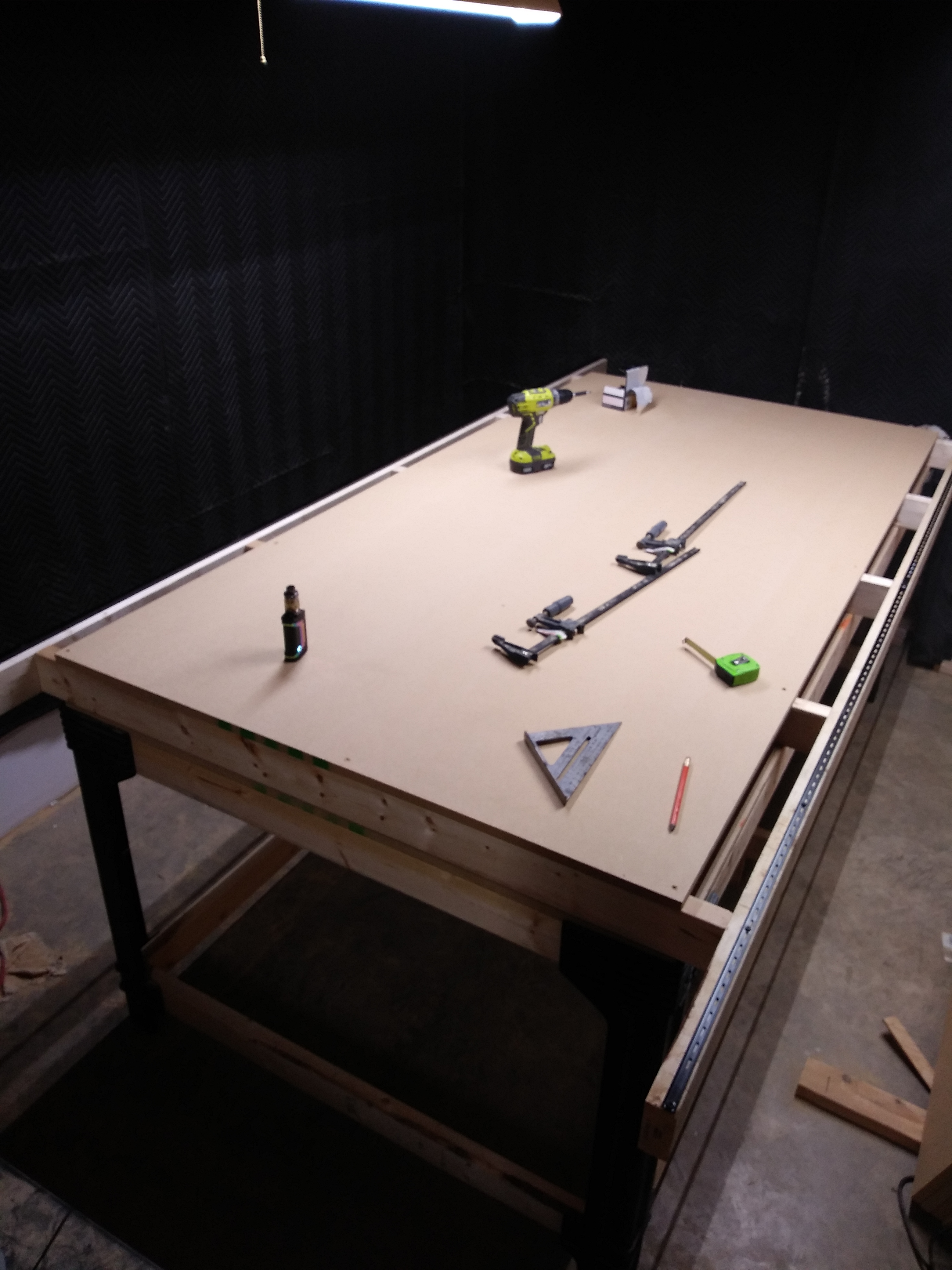
I FINISHED MY TABLE! Probably seems like I’m getting super excited about something hundreds of people have done, but I finally got MINE done! And that’s huge for me because it was honestly the hardest part.

So if all goes well tomorrow, I’ll start assembling the machine, and get those damn tubes cut to size and cleaned up. Not sure I’ll get to wiring it, but I’m going to plan on going by my shop in the evenings after the 9-5 and slowly make more progress. Hopefully by this weekend I’ll be getting her dirty!
4 Likes
Now the fun begins!
1 Like
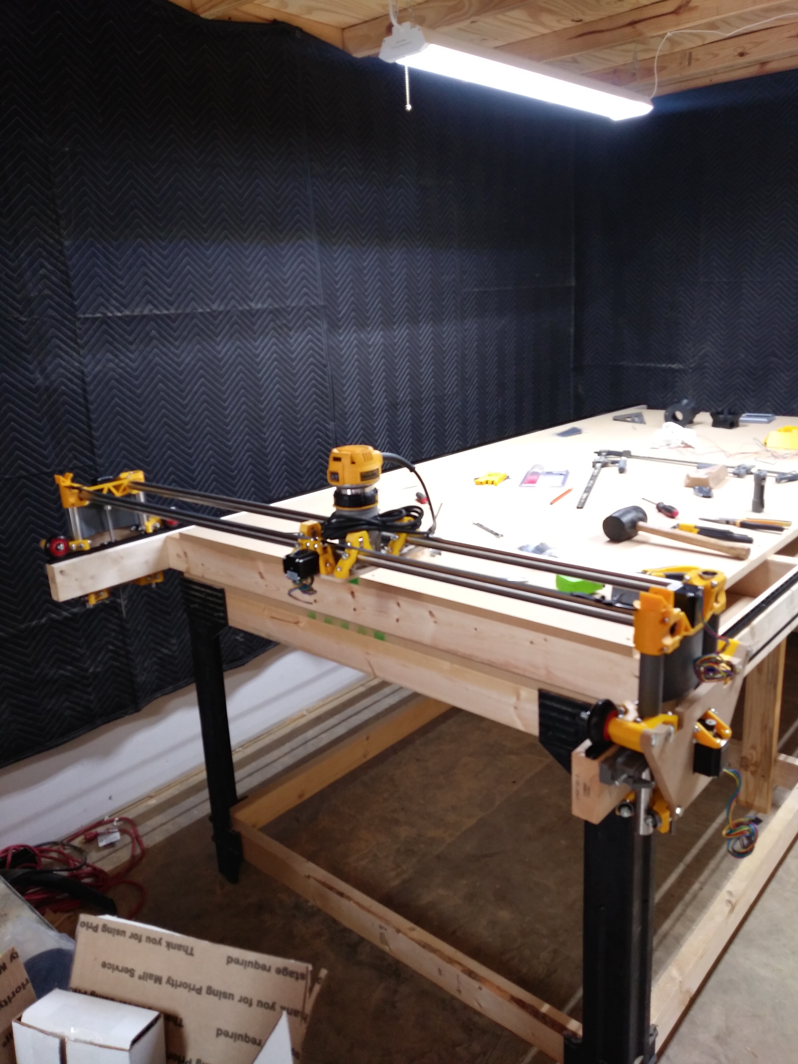
Fun indeed! I didn’t even get frustrated the first time. Thanks to the extremely clear instructions. What I have so far!
!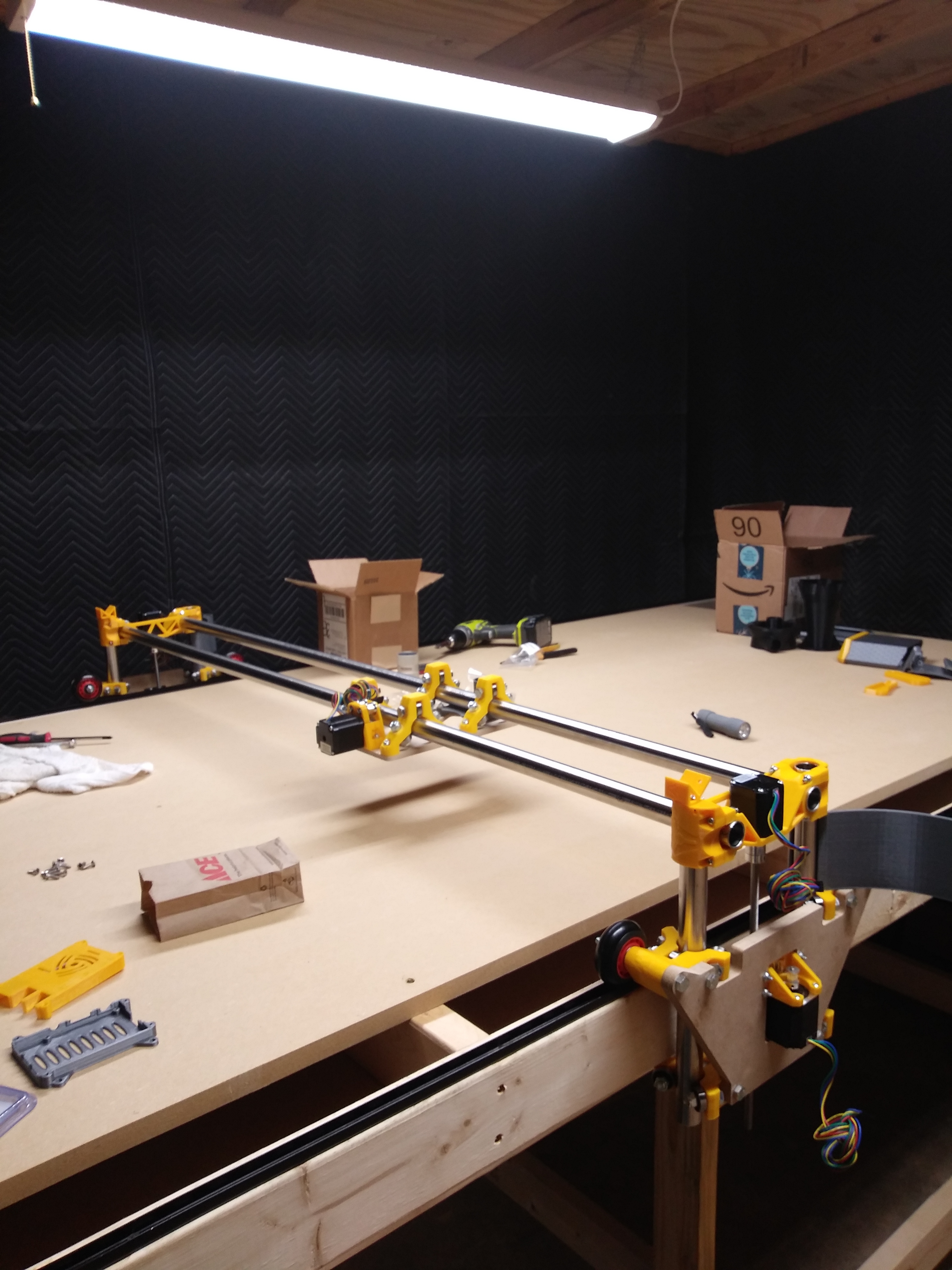
I do have one question about the assembly so far. What’s the best way to square up the machine? Not on the table, but with itself? Like is there a method for making sure the y plates are square with the longer tubes? I’m having some tube rubbing when running down the 2x a little and i think it’s because my y-plates aren’t exactly square with the rest of the machine. Or will the belts help it travel a more straight line? I feel like maybe it’s because I was moving it by hand too that it was getting out of line… Any tips or advice here would be appreciated.
Loving everything so far, can’t wait to wire this bad-boy up tomorrow!
1 Like
I do the best I can with a tape measure across the rails. Test drive it down the table a few times and look for obvious issues. The final test is plotting out the four corners with the machine and a pen. I shim the belt stops with tape to get it as perfect as possible.
1 Like
Thanks man! I also read the build instructions again, and I think I may have the XZ Side Belt, and XZ, a lil’ too tight. I haven’t put any real tension on the tensioners yet, except I realize now, that the Z rollers, the bolt that i tightened to mount it is actually the tensioner, So I will check that today when I get to my shop as well. Thanks for all of the help so far!
1 Like
@vicious1 man… Your layman’s terms always ‘just work’ for me. LOL Thanks for making it easy for me to understand! I did your advice, yet again and my gantry almost mowed me down it was moving so smoothly. Right now how it’s sitting it’s not level, I’ll do that once I move it towards the wall where it’s going to be permanently. For now It’s on an unlevel part of my floor and as soon as I started moving my rails, I look up, and here it comes like a freight train haha
I also loosened up the XZ & XZ Sidebelt pieces and it really made alot of difference, guess I had binding because they were so tight. For anyone building a lowrider, don’t clamp those down. Leave a gap between the 2 pieces. Trust me on this.
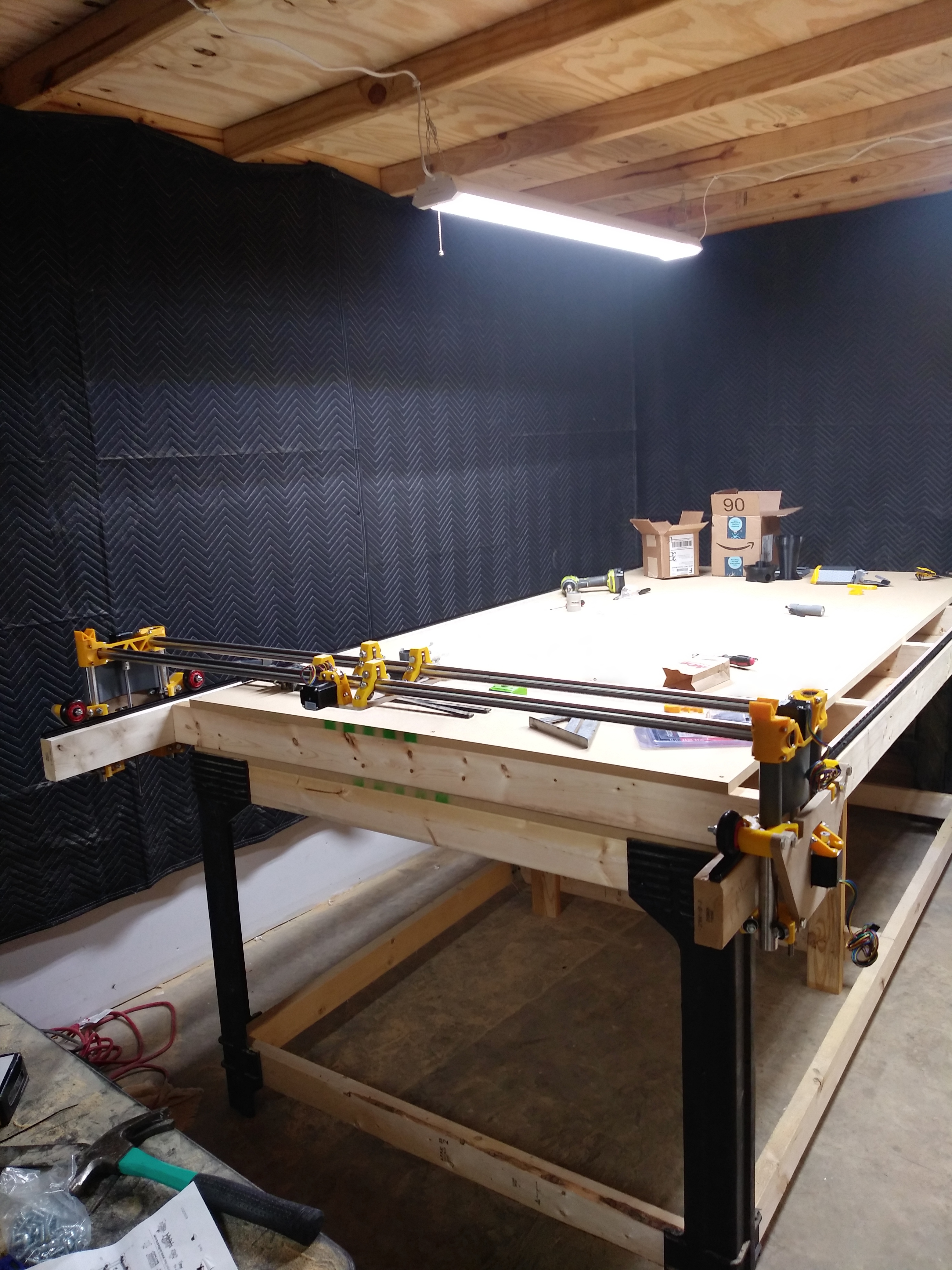
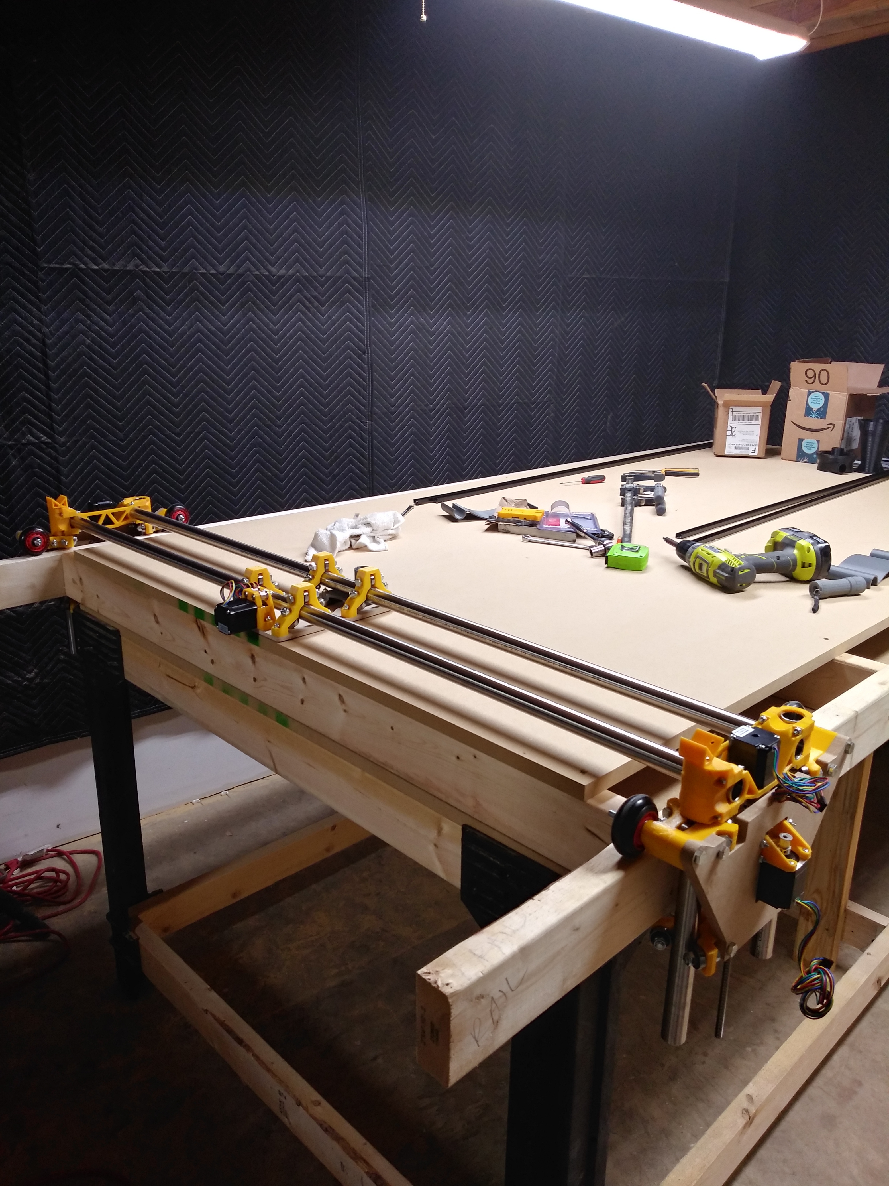
SO. On to my progress photos for the day!
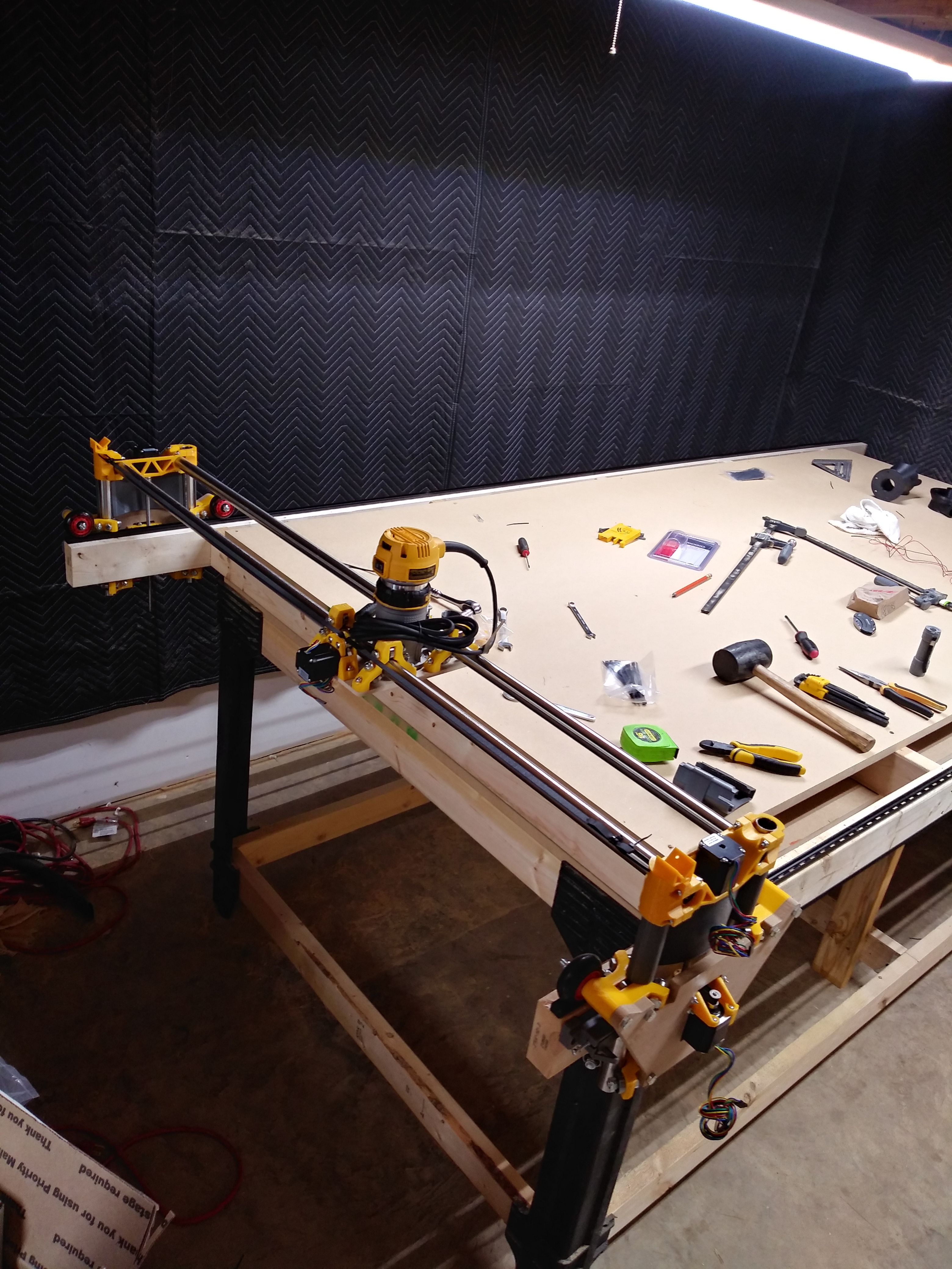
Got my belts on, and the dewalt fresh outta the box, and mounted on the 611 Plate.
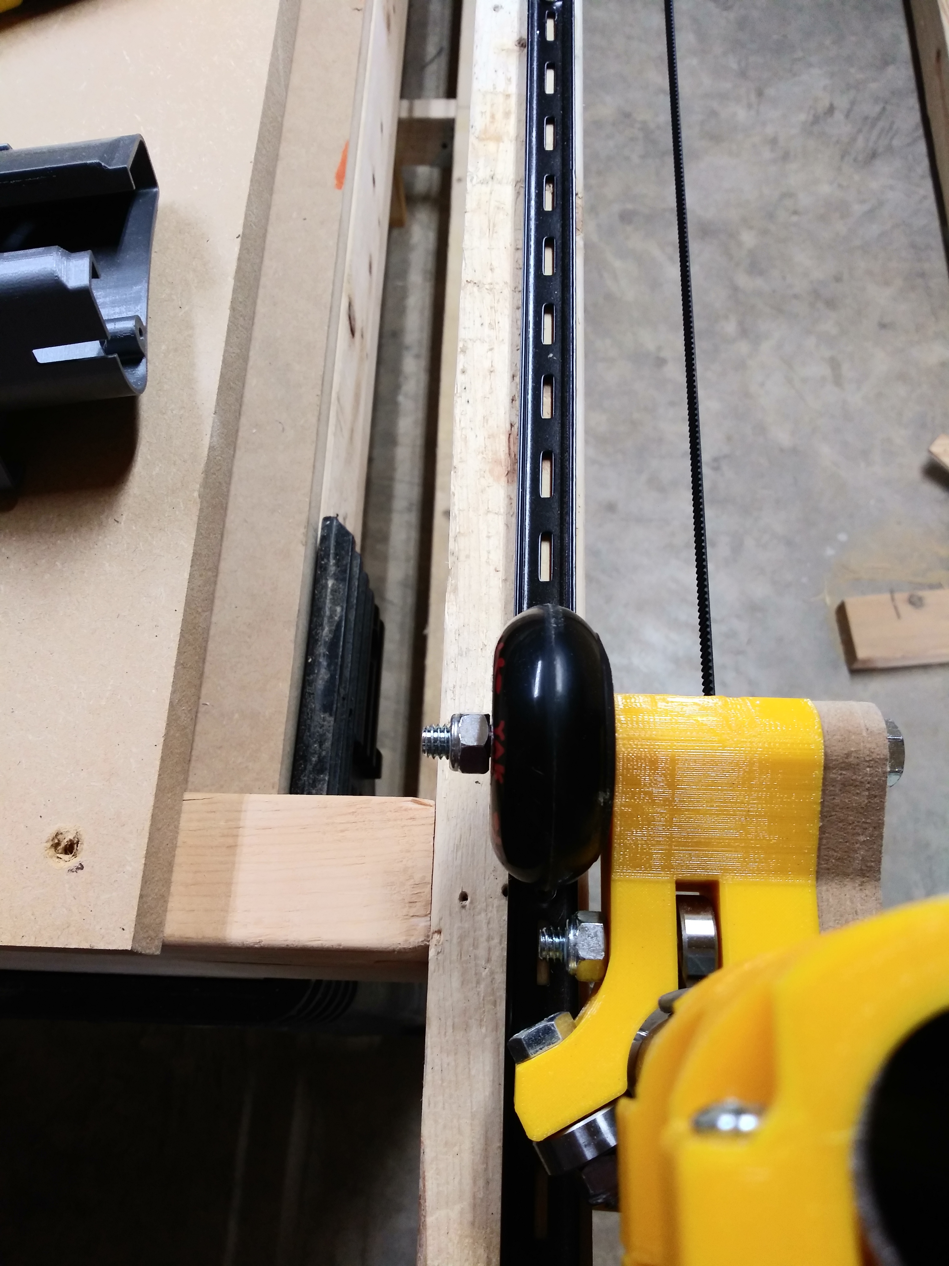
My makeshift rails that it now follows smoothly down the entire length of the table. No climbing any more, no rubbing, just smooth movement!
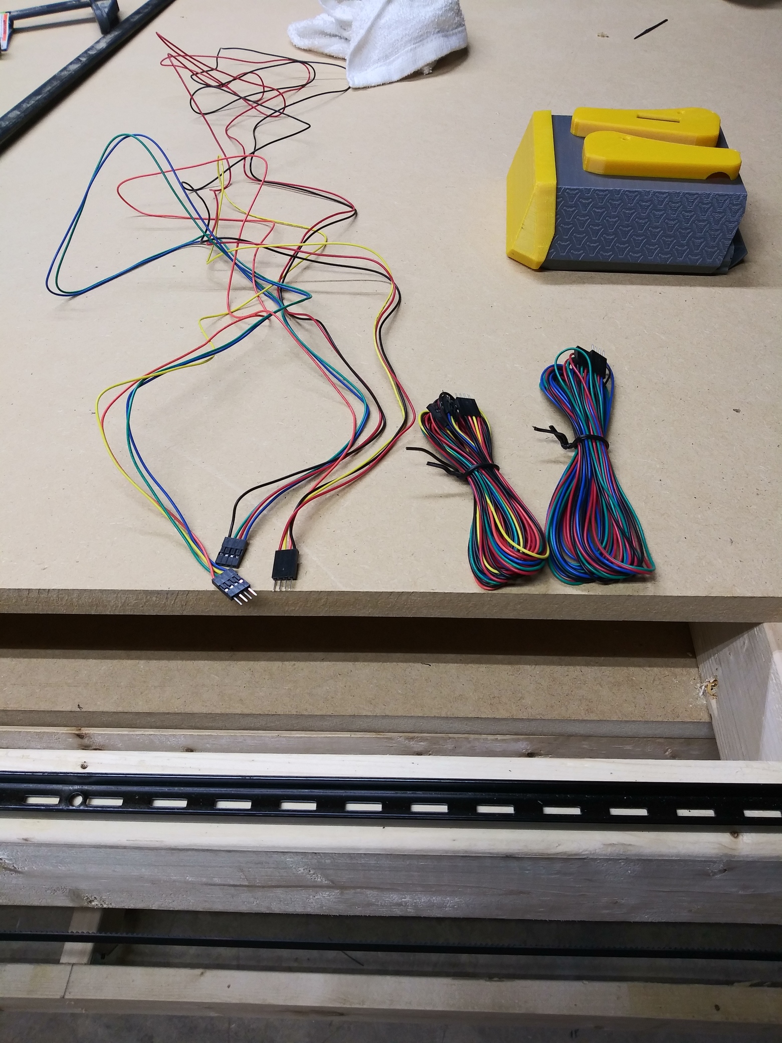
And now for my question of the day… What are these wires for? Are these the extensions? If not, how is everyone running their wires from the far side through the tubes over to the Rambo? Thanks! And thank you for all the help! This community never ceases to amaze me!
1 Like
Wires are for Z&Y, the extension is for the X. I have mine sitting on a piece of Aluminum angle and through the tubes. I think I have some pics of my wires in the instructions or thigiverse.
So the one on the far right in my photo is the extension? I’m actually using your photos on thingiverse as reference since your wiring is so cleanly done. I also have a piece of alum angle as per the parts list page, I just have to get it cut.
I was planning on wiring it all up tomorrow after work. I got some mesh sleeving, and heat shrink to keep everything nice and clean, just need to stop by Harbor Freight and grab another heat gun.
Yep that is for teh X and the other two will look like the first picture.
https://docs.v1engineering.com/electronics/steppers/
It is a little tricky to get them connected through a full sized build but there is just enough length, so tape them and be creative.
I have been chewing on a design for a new LR table, and the way those 2x4s stick out over the edges makes me really want that. I still want to try doing end joinery. I could add a cheap pipe clamp vise and then start cutting the ends of boards. Something like this:
https://jayscustomcreations.com/2015/08/easy-strong-huge-pipe-clamp-workbench-vise/
This is definitely going to be in the plans now…
5 Likes
That would be cool, and gives me some ideas to utilize that area!! Thank you! I actually did that for tool changes. Gives me room to work when changing bits. But you’ve opened up a whole new concept for that space as well! I was going to put the remaining length of the 2x’s on one end, but didn’t want any flex, so I split it, there’s the same amount on both ends. I have a job box that I was thinking about putting at the far end since the lid opens from the top, would clear everything. The possibilities are endless in this DIY world!
1 Like
One more question about the LR as a whole, since today I’m hoping to be actually moving this thing with the steppers, I have a question that’s been looming. So maybe it can get answered before I get to my shop this afternoon.
How does the machine know the size of the build area? I’m NOT a software guy by any means, so I’m hoping this isn’t going to be as challenging as I’m making it out to be in my head, and I can stay away from compiling firmware. I looked around the build pages but didn’t see any mention So I’m kinda hoping it’s something simple like estlecam will set the size or something. lol
And speaking of Estlcam… Can I run the machine off of estlecam without having to mess with Repetier? There’s going to be a usb connection to the machine, until I setup Jeff’s raspberry pi system.
It has “soft stops” in the firmware that you set before flashing. Or you don’t worry about it, and not try to cut anything bigger than it can actually cut.
Not with the controllers from this site. Estlcam requires a specific controller/motor controller combo, with estlcam firmware flashed. I have a 10 foot usb extension cable attached to mine and just run it from a laptop. I have a screen on it, but I don’t think I’ve ever run a job off one of the screens.
Thank you @barry99705 Barry. I was hoping that I wouldn’t have to do anything special for the size of the table. Relief there.
So when I had my Maslow, I would just build my design in cad, then take it to cam (estlcam) then from there I’d feed that gcode to the Maslow (because i set my cad to the full sheet, then create start points in cam so I’d know exactly where it was going to start).
That same principle can be used here? Like I’m guessing repetier would be good for jogging the machine around, but I also have that option from the LCD. I can put start and end codes in estlcam, so repetier isn’t a ‘must have’? Or do you need it for some driver requrements or something? Again, not a software guy at all lol So apologies if that question is dumb.