My new Core XY project [Timber Bot V1.0]

Still working on this in the background as I have time. Most of the work has been virtual in OnShape. So I figured I would share an update on the design status. I have figured out a very easy way to get this (and maybe several other) Direct Drive Extruder to mount up. Its a great Extruder design and I didn’t want to have to reinvent the wheel. So this is the one I will use for the 3D printers I am building. Here is a photo of it mounted to an early prototype. I have designed some better cable management but don’t have physical prints yet.

Then I started looking at the Z axes. So many options but none of them seemed like an easy fit for me considering I needed a design that can fit a few different bed sizes. So again I started to roll my own. I have not printed any of the prototype parts yet but that is next on my todo list. After I am convinced it will move correctly I will make the frame pieces that the Bed will attach to.

I also started to plan out the Wooden box frame. Nothing special.

It’s a fun project. But there is still a LOT to do. I need to add endstops and other wire management. I plan to cut the first full set of wood pieces soon. And start printing a full new set with better quality print profile. I have been using super thin hollow parts so far.

3 Likes

Inspired by your machine, Aaryn, and excited to revisit CoreXY… I’ve begun my own machine build. I, too, have a fair stash of parts and a Prusa printer always on the ready so I determined to try to adapt your design and use parts I have on hand, as much as possible. Not having appropriate length commercial rails in my stash, I’ve adapted and printed these BB-bearing rails and used some of the zillion or so 608 bearings I have on hand for idlers. I also had a few shorter 2020 extrusions on hand and have elected to use them, primarily just for support. Here’s the basic machine configuration so far…

I’m making just a basic CoreXY machine – probably just another laser engraver – as I don’t expect the printed rails would last too long in a 3dprinter. I’ll probably just add the Z-axis from my earlier post and mount one of the little Neje “6W” (~2.5W) laser modules I have.

I’ll start a new thread for my build. This is just a fun project (NOT a serious machine!) to keep me off the streets but I want to say thank you for the CAD design (your Onshape skills are way better than mine!) and the inspiration to get off my duff. Thanks, Aaryn!

– David

2 Likes

That is SOOO COOL! I love it. I am really interested in the BB rails. Such a cool idea. I think I will use that for the Z on the Laser machine I plan to make as well. I wonder if they would work well enough for a Sand table build. Or maybe just some fun robot plotter for my kids to play with. I love these kind of fun projects. I’ll be interested to see how your little machine turns out.

The 608 Bearings. I probably should have just used those as well. I have about 80 of them on my shelf. That was my original plan. Who knows. I like to tinker so much I may eventually redesign the CoreXY parts to use them instead. Because the bearings I chose are harder to find.

I enjoy OnShape. It is fun for me. I learn new stuff in there every week and it all keeps adding up. Just yesterday I figured out how to create one part studio that is used to hold all the variables I want. Then all my other sketches derive from that. So I can make changes to the size of the machine in one file and it will update ALL the other parts and assemblies. Still a lot to learn though. I want to learn more about curves and the sheet metal tools.

1 Like

replied so i can follow along. want to build a corexy next but cant make up my mind which one. First one was Railcore, then Voron and then GridBot. I have an Ender5 but hate the cantilevered bed.

Just as a note. You can change your watching settings without replying. The drop down is right next to or near the reply button.

A few steps forward and one large step back.

I made a lot of exciting progress on this project but then I broke my MPCNC. With my limited time that I can spend in the garage I am not sure when I will be able to get it fixed. It’s just a wiring issue for one of the Y steppers but that will take time.

Exciting progress. Here is a list of the features I have added since I last posted.

Named the machine

  • Instead of calling it “My Core XY” I now call it “Timber Bot”
  • Cool logo to laser engrave onto the side to follow
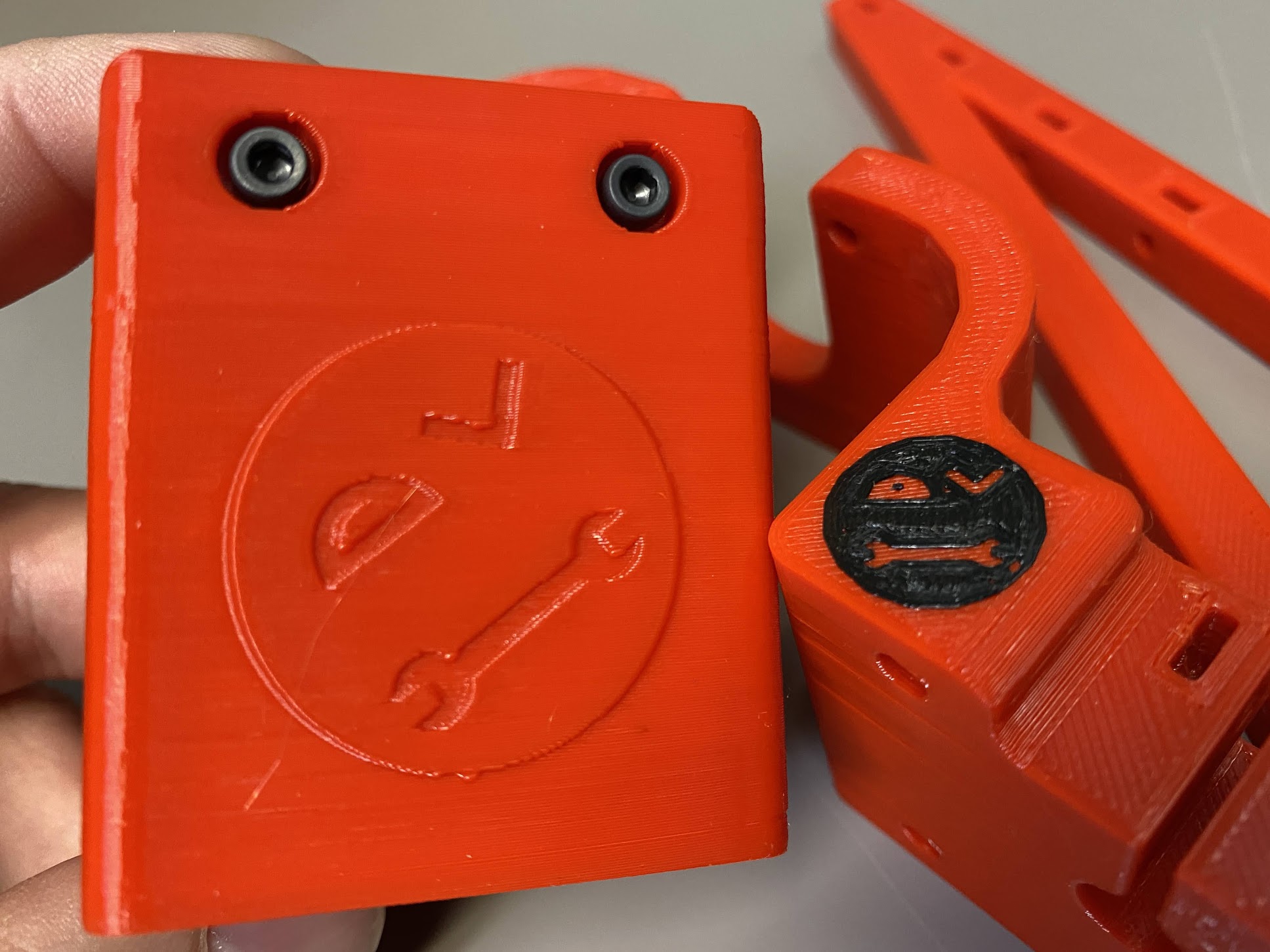
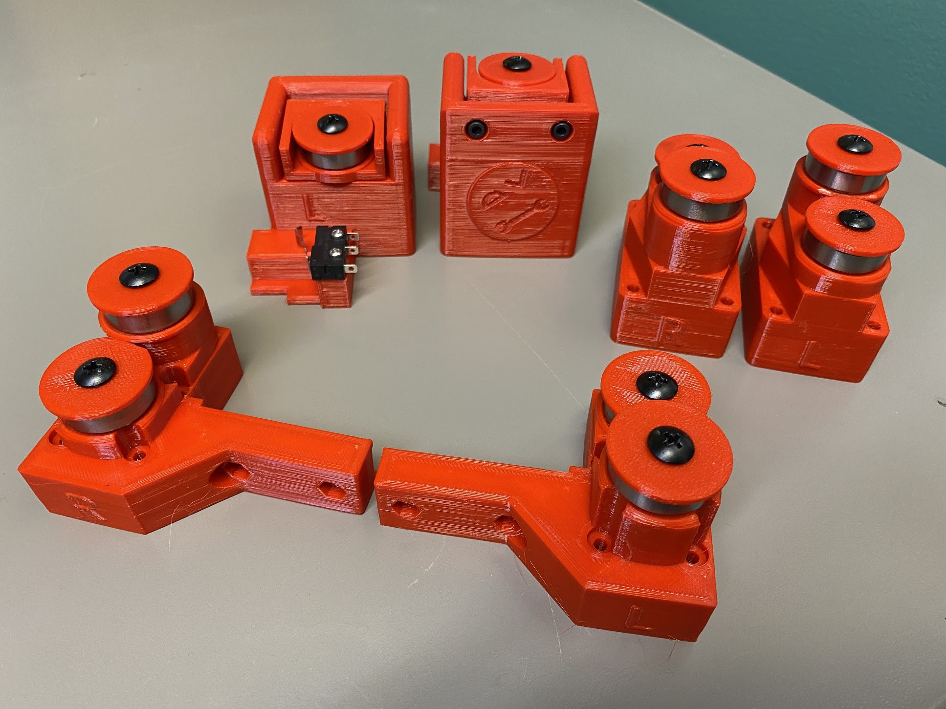
  • I added my personal Tinker Man Logo to several of the 3D Printed parts

Parametric Design OnShape Document

  • The Entire machine model size can be controlled by changing three variables in the document. Three Variables are X Rail Length, Y Rail Length, Z Rod Length
  • CNC cut Wood pieces scale to fit the variables
  • Assemblies (Renderings) Scale to fit the variables

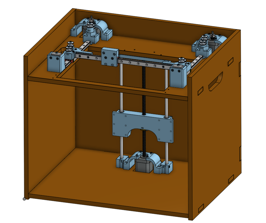
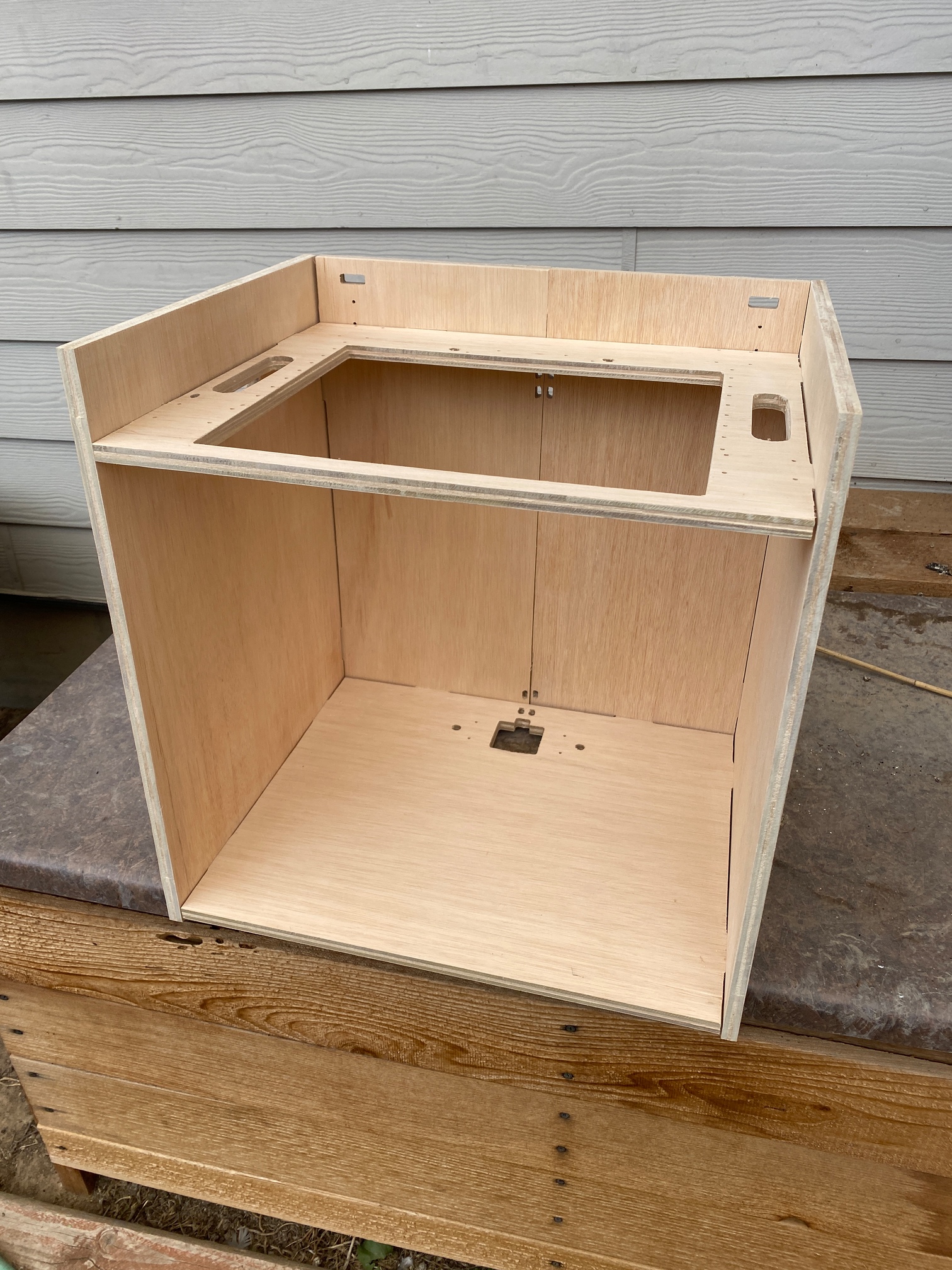
Added wooden box frame ← not tested yet do to broken MPCNC

  • All the pieces fit together with simple joints
  • Glue together rather than screws or angle brackets
  • Holes for screws, cables and zip ties
  • Uses 12mm wood (11/32 inch)

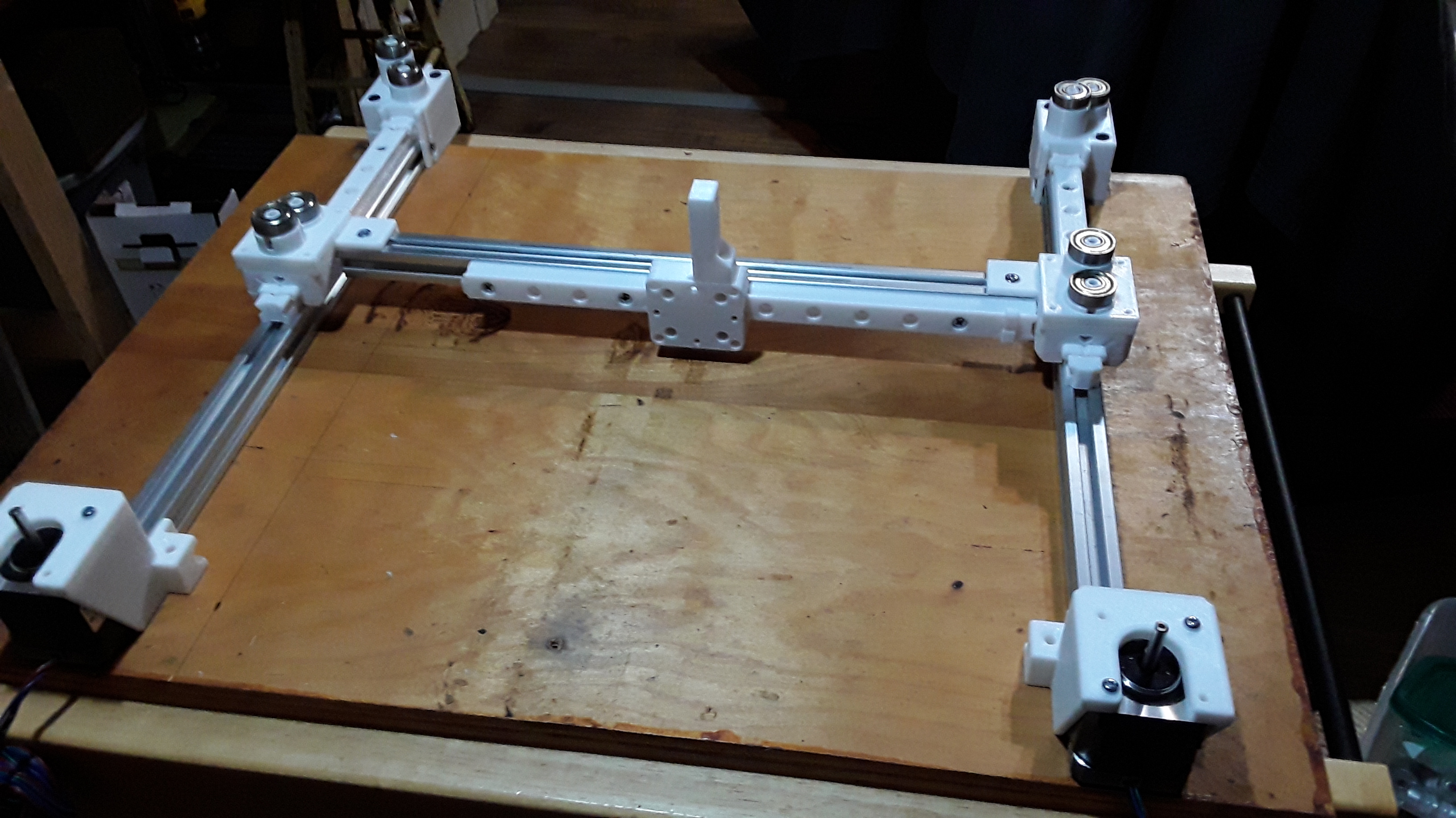
Changes to the Core XY

  • Added Mounts for X and Y Endstops
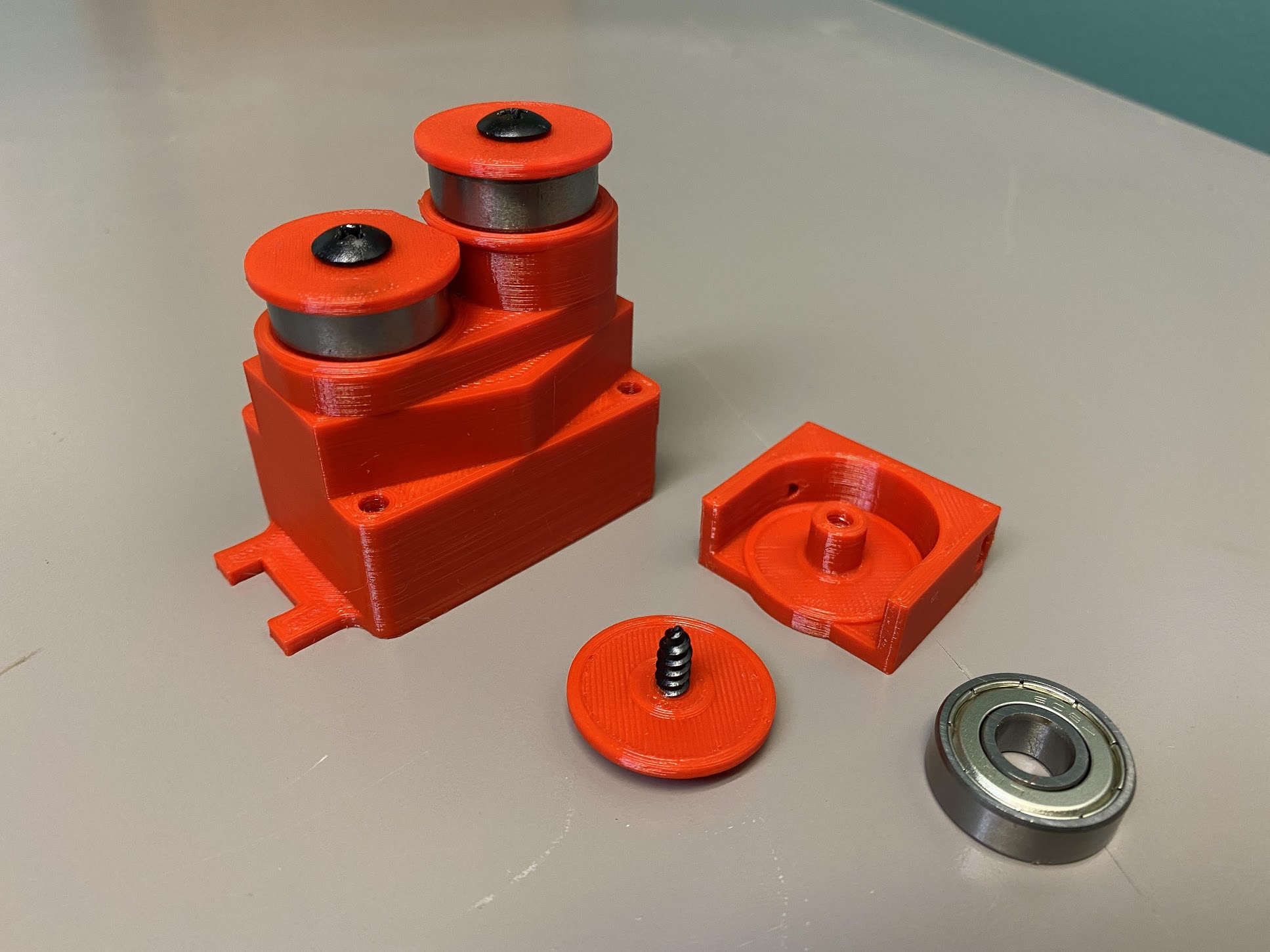
  • Changed out all the 3 mm bore Idlers for 608 bearings. (Special thanks to @dkj4linux. David’s Idea of the axle and hubcap design were Instrumental. See details below)
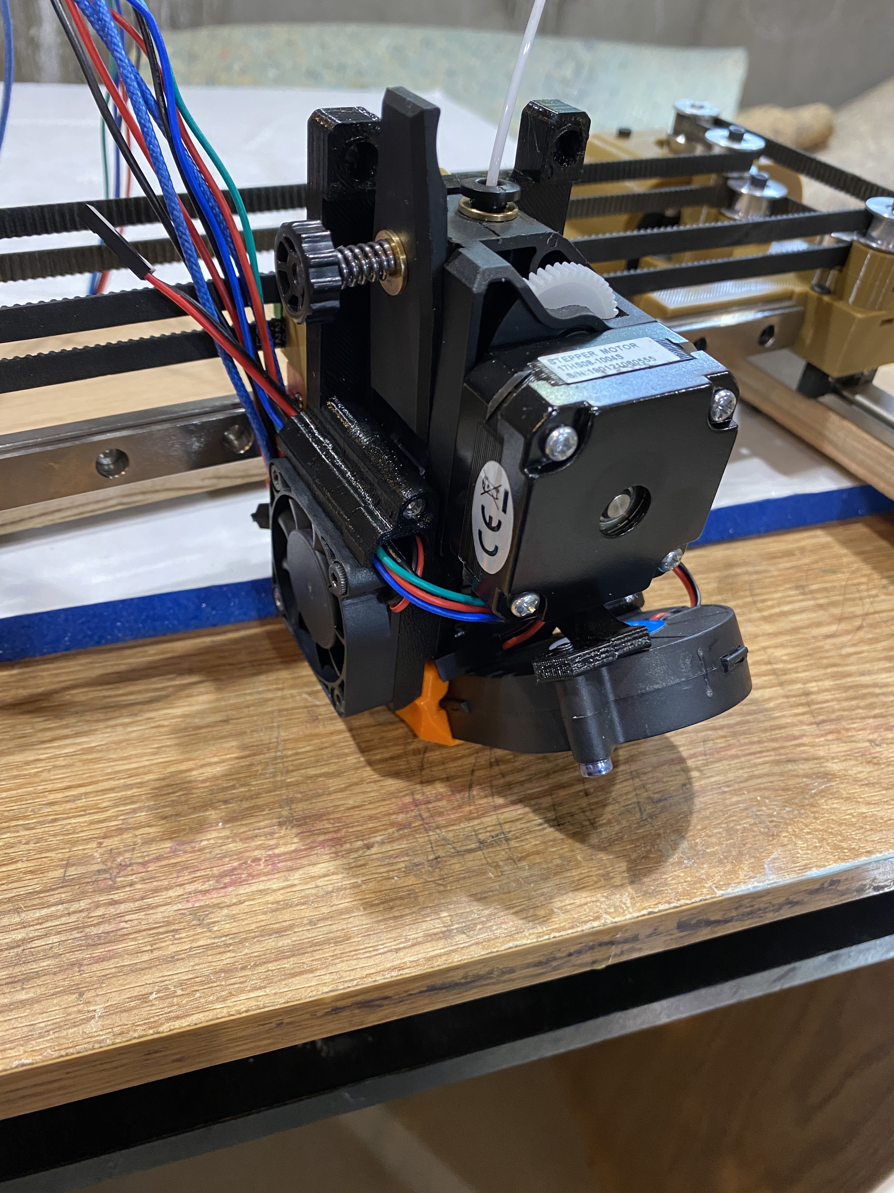
  • Added more space for the tool head
  • Added more space the rollers to move past the ends of the linear rails. (See below for details)

Added full Z axes

  • Uses Leadscrew instead of belts
  • Versatile design to fit many bed sizes & configurations. Uses a CNC cut wood piece to mount the bed to (See below for details)
  • This is a single motor build so it can probably only handle beds up to about 250x250. I’ll eventually test it with my 300 x 300 to see if I will work.
  • Smooth Linear LM8UU bearing motion (THIS IS FREAKING HUGE!!! See below for details)

Now for some of the details.

Some of my ugly Tinker man logos. Maybe I’ll eventually replace them with the Timber bot logo I am thinking about.

How to adjust the size of the Timber Bot
https://youtu.be/IUe8MdWHR5c

When I started working on this project I wanted to use 608 bearings but I couldn’t think of an easy way to implement them. So I bought some idlers with a 3mm bore. Bad idea. This actually complicated the design and made the build process even harder. Well copying David’s idea of how he uses 608 bearings on his core XY laser engraver made things really easy. It made the build bigger. Takes up more space but it is SOOOOO worth it. Much easier to design, print and assemble. They are also a lot stronger. Thanks again David.

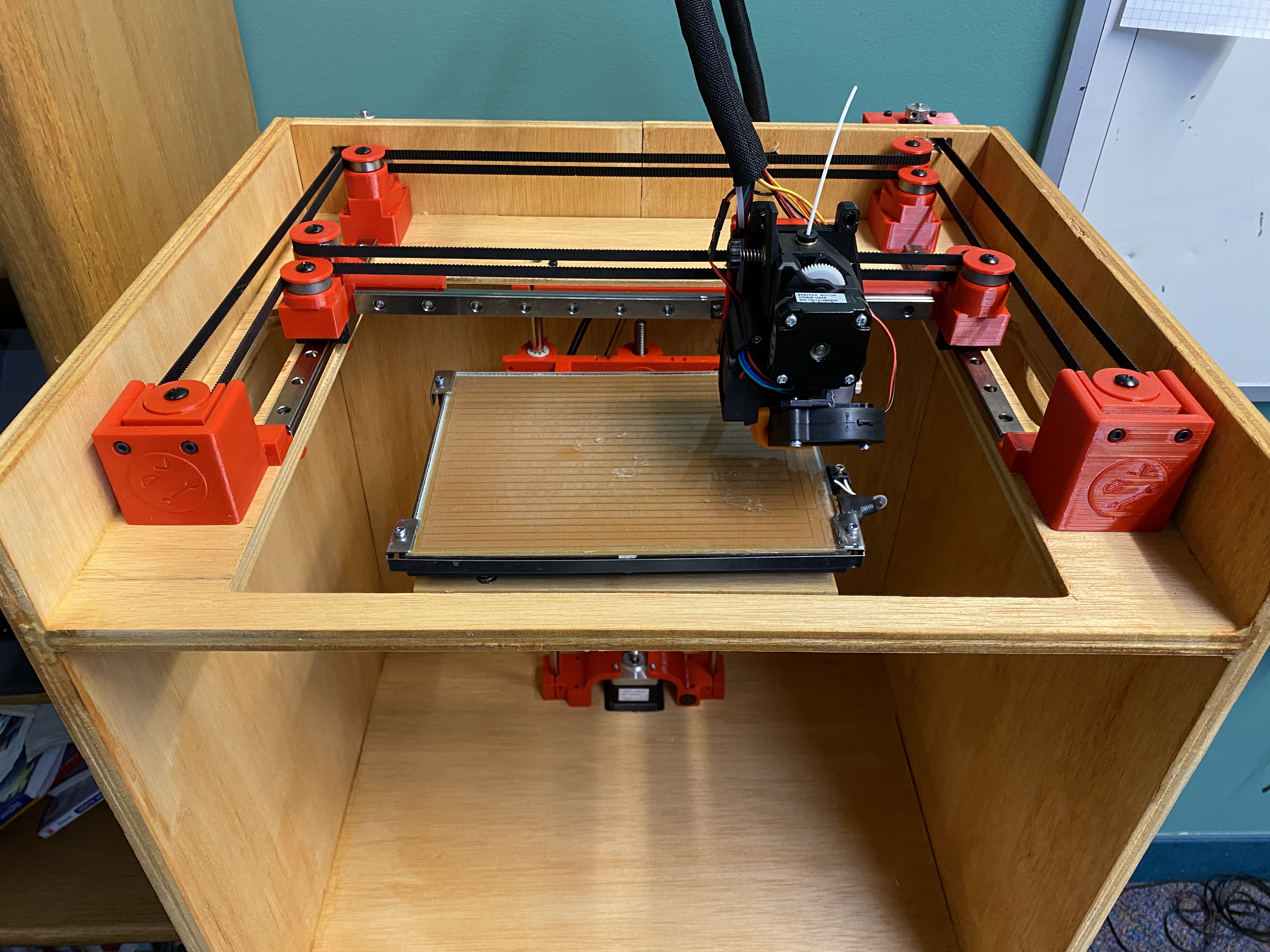
I noticed that the Linear rails can move about 7 mm past each end before any of the ball bearings leave the steel track. So I made the plastic blocks on the ends give them an extra 5mm of space. This way I gain an additional 10 mm of movement on each rail.

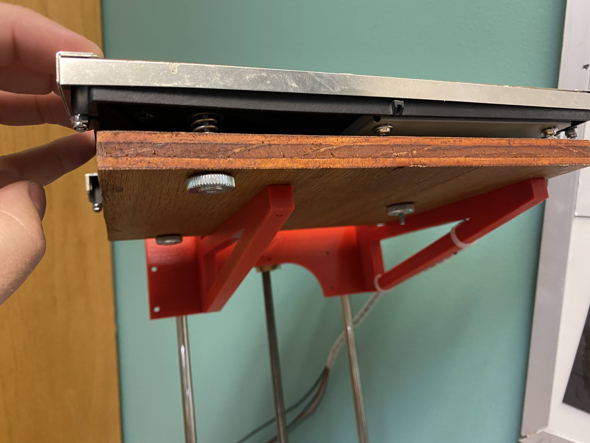
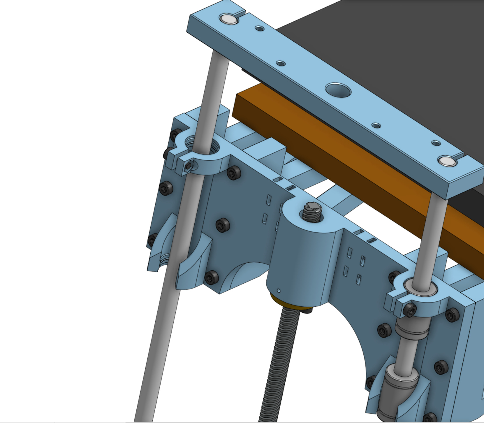
The Bed Mount has up to four braces. In this photo I chose to only use two that won’t conflict with the adjustment screws. I think this is a very versatile design. It should be able to mount up to many bed shapes and sizes. You will need to make your own custom wood piece. Later I will make one for my 200x200 bed and try another one for my 300x300. (210x160mm bed pictured)

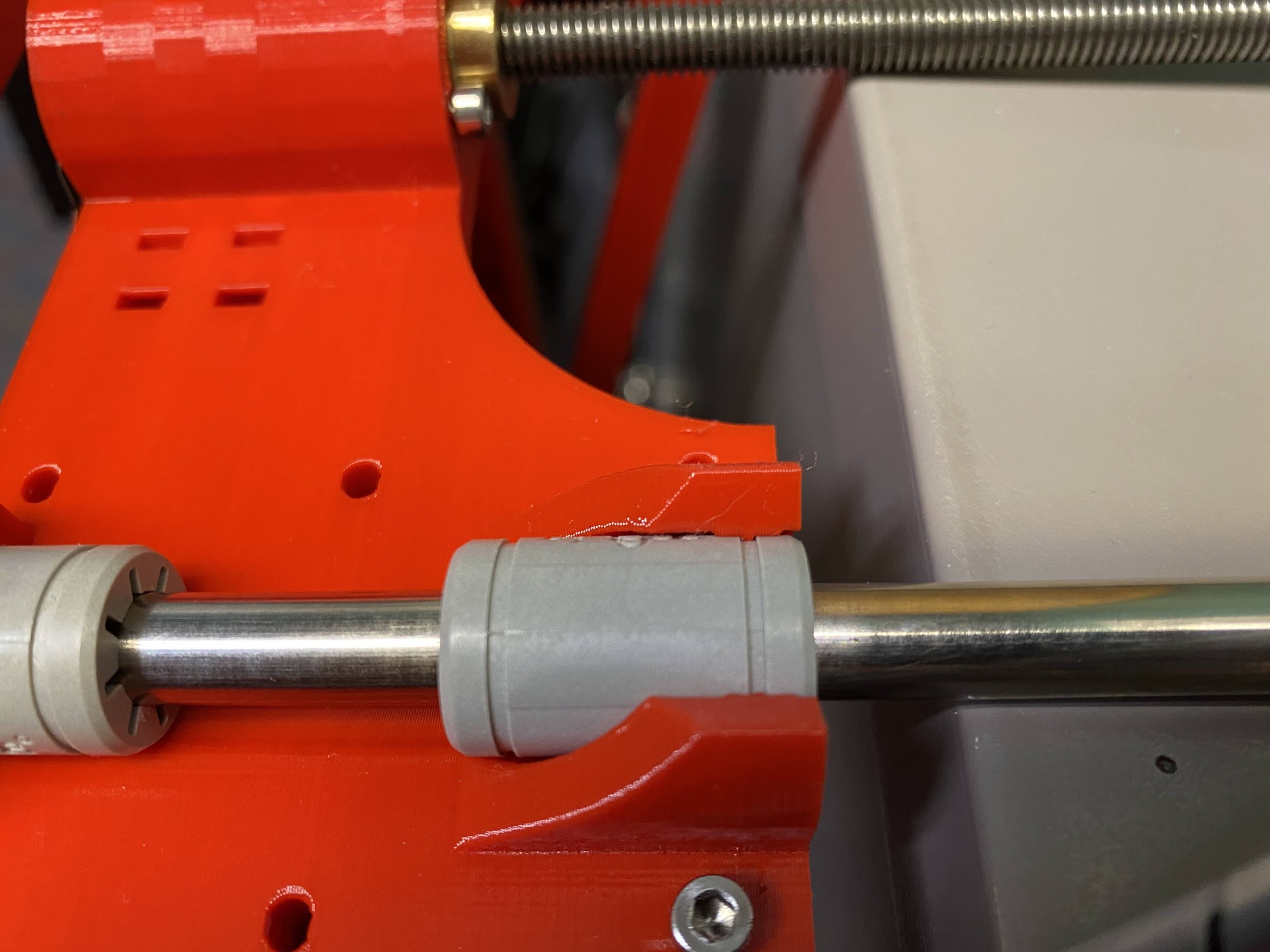
I am EXTREMEMLY PROUD of this next one. I have tried to design MANY machine parts that hold LM8UU linear bearings. The biggest problem is that FDM 3D printing has so many imperfections that the bearings don’t ever line up perfectly. My first version on this Z carriage was horrible. I don’t have pictures but when I put two bearings in it and tried to push an 8 mm smooth rod through it … well lets just say it was very difficult to push through. Think hammer as a solution. So I finally came up with an idea that solved the problem. It removed about 95% of the friction caused by the bearings not lining up. Instead of trying to hold the full length of the bearing in a 3D printed sleeve I only hold about 4 mm of each bearing. So they can be held firm but will still be able to aim. This makes it so they can very easily align with eachother. I am super happy with how well it works.


In this next photo you can see how I tight clamp the top of the upper bearing and then loosely clamp the bottom of the lower bearing. This will prevent a heavy load on the bed from causing the carriage to lose it’s grip on the bearings. That should prevent the bed from getting out of level during a long print.

If you look close (zoom in) you can see the 4 mm wide section that holds the edge of that bearing into place. The upper clamp has a similar design.

Well that is all I have for now. Until I get the MPCNC working again I can’t cut the wood pieces to test a full build. It may take me a few weeks to get another update. I have updated the original post with a link to my Google photo album if you want to peek at a few other images I have taken.

4 Likes

This is great looking. You’re in CO, right? Let me know if you need something that I have (we’ll both take covid precautions, of course). But I have a LR1 and a few boxes of spare printer/CNC parts.

I do like the 608 bearings. I am constantly worried the little idlers are going to jam on my grid bot.

BTW, The grid bot uses LM8UUs with a flange on the top. The big difference is that it isn’t a cantilevered bed, so there isn’t as good a reason for the second set of bearings, vertically, so it instead has 4 in a plane across the bed.

Yeah! Thanks for the offer! I was excited to take you up on helping me cut some of these prototype pieces. I would enjoy finally getting to meet you. But I decided to at least try to fix my machine first. Turns out my wiring is fine. I blew one of the coils on a motor. Oops! Must have happened when I crashed the bit into a metal screw I was using to clamp the wood down. As a mental note I should probably turn down the current levels in my firmware. Can that be set via gcode for the Rambo 1.4 board? I’ll have to look that up.

That is a great idea. When I attempt to mount my 300x300 bed I imagine I will need to switch to a setup like on the grid bot.

Well funny story. Right after I replaced the fried motor last night I tested the machine and suddenly the X axes was behaving the same way. One motor was acting like one of the coils was bad. Turns out I pulled a wire right out of the dupont connector while I was debugging the original problem on the Y axes. It was just like that moment in back to the future when Doc Brown pulls on the cable to plug it in and it unplugs from another spot.

Well my Dupont connectors and crimps were at the office so that was the end of tinker time.

But I was able to rethink a few things and make some adjustments to the OnShape document. I made the wood pieces adjustable to use different thicknesses of wood. I figured that might be a good idea. I also decided to move the X Y Stepper motors to the rear of the box. Moving the Steppers to the rear uses a LOT less wood. All of the wood pieces got about 30-40 mm smaller in at least one direction. I originally wanted them to be removed from the heat that might build up inside the box anyway.

Last update for now. I finished the Timber Bot logo I want to laser engrave onto the sides. Not super fancy but I like it.


More photos in the google album.

3 Likes

That’s nice. I thought about doing the same with my steppers, but wasn’t terribly sure about my skill level in getting it done correctly. I also ended up having a lot of space on top for the filament to move around in. Long story short, it’s gonna be a heavy box. Being able to use thinner wood would be great, but all I had in the garage was 1/2 mdf, soooooo…
Your design is looking REALLY good now!

Got the MCPNC running again over the weekend. Cut a full set of pieces for my first build.
I should have sanded it down more but I was too impatient. I slapped some stain on it and will begin assembly soon.

I noticed some of the screw holes are too close to the edges and fixed that for the next one I build.

I added some pictures to the Google album. (Link in the Original Post)
But here is a photo before glue or stain.

3 Likes

That looks clean! I like the plywood way better than mdf

1 Like

Lol. Thanks. That might be true in the photo. But up close the edges look bad. I need to sand them and maybe glue on an edge. Later. If ever.

1 Like

Fully assembled and wired. Now to test and calibrate. This is an exciting milestone but the beginning of the most boring part IMO.

6 Likes

OH SNAP!!! Its doing that printing thing!!! I am so stoked! It took about 12 hours to get all the configuration stuff done. These Duet boards are cool but new to me so it took forever. I also had trouble with Core XY. X was moving the right direction but Y was opposite. Took forever to figure out the problem was the steppers were plugged into the wrong spots. AKA The X motor was in the Y plug and Y motor was in the X plug. Crazy.

PETG is probably not the best for a benchy but at least this way I can see what needs to be tuned.

As you can hear in the video it is louder than I would have thought. Even after I enabled StealthChop. I am not sure if that noise if coming from the belts or the motors. It may actually be the belts. The faint chirping is from the part cooling fan. Not sure why it chirps faintly when it’s speed is less than 100%. I remember the Prusa MK3 used to do that. They must have solved that with firmware but I don’t know if it can be solved with a Duet board.

I have made several minor tweaks and changes to some of the printed pieces and how they connect to the wood. I also decided to move where the Y endstop microswitch is mounted.

I need to make some more tweaks to the Top Wood piece that all the Core XY stuff mounts to. Change some of the measurements. I also want to add a power switch to the front that is easy to reach. While I am at it I might as well add a switch for some LED lights.

In any case I am getting closer to calling this project close enough to done that I will publish the STL files on PrusaPrinters.org. After that I want to build the laser engraver version of the Timber Bot. The differences will be mostly in the wood pieces so it is shorter with air flow design.

5 Likes

Great!

Mine have stealthchop set up to 100mm/s, so whenever it goes over 99.9mm/s they get loud. It sounds louder than that though. That might just be your belts. There is a click when it switches directions though. That makes me wonder if there is backlash somewhere… Maybe it’s just a loose pulley grub screw?

Great progress though. It is nice that it is making 3D stuff, at least.

1 Like

Thanks!
Stealthchop is cool. The movement was a LOT louder before I turned it on. I don’t really understand the setting though. I had mine set to T100 at first but then I noticed that T25 made it quiet at faster speeds as well. Soooo… I don’t know what the T value stands for.
Yes there is a clicking. Thanks for pointing that out I may have ignored it for a while. Good suggestions for potential causes. I noticed the benchy had some misaligned layer lines so there is a problem. I’ll have to track that down. It may also be the hubs in the middle of the 608 bearings. They are not 100% snug so the bearings could potentially move .05 mm or so. And I did skip using loc tite on the grub screws. I need to correct that.

1 Like

This looks great, any concern about the wood warping and throwing everything out of square? Maybe its not a problem in CO… in Michigan we have such huge temp and humidity swings I worry about making anything square out of wood (I have had speaker boxes split from the pressure :/) I can’t wait to see how this turns out.

Maybe I’ll make one out of acrylic :slight_smile:

Dude, I showed up to ask if your machine was noisy. Mine is loud as HECK. I think a lot of it is the motors echoing and vibrating through and around the mdf because they are more of less rigidly connected to the sides.

I am not that worried about humidity here in Colorado. When it rains it gets humid enough to ruin PLA filament but that’s about it. During winter months it actually gets extremely dry here. I grew up in Arizona and was surprised to find it gets more dry here than Arizona.
To your point though I really should check to see how square this thing is. Didn’t Ryan make some test print pieces regarding squareness?

With plywood, in moderately sized pieces like this, I think it will stay still. But all my experience is from Colorado.

1 Like