Thanks!
Stealthchop is cool. The movement was a LOT louder before I turned it on. I don’t really understand the setting though. I had mine set to T100 at first but then I noticed that T25 made it quiet at faster speeds as well. Soooo… I don’t know what the T value stands for.
Yes there is a clicking. Thanks for pointing that out I may have ignored it for a while. Good suggestions for potential causes. I noticed the benchy had some misaligned layer lines so there is a problem. I’ll have to track that down. It may also be the hubs in the middle of the 608 bearings. They are not 100% snug so the bearings could potentially move .05 mm or so. And I did skip using loc tite on the grub screws. I need to correct that.
1 Like
This looks great, any concern about the wood warping and throwing everything out of square? Maybe its not a problem in CO… in Michigan we have such huge temp and humidity swings I worry about making anything square out of wood (I have had speaker boxes split from the pressure :/) I can’t wait to see how this turns out.
Maybe I’ll make one out of acrylic 
Dude, I showed up to ask if your machine was noisy. Mine is loud as HECK. I think a lot of it is the motors echoing and vibrating through and around the mdf because they are more of less rigidly connected to the sides.
I am not that worried about humidity here in Colorado. When it rains it gets humid enough to ruin PLA filament but that’s about it. During winter months it actually gets extremely dry here. I grew up in Arizona and was surprised to find it gets more dry here than Arizona.
To your point though I really should check to see how square this thing is. Didn’t Ryan make some test print pieces regarding squareness?
With plywood, in moderately sized pieces like this, I think it will stay still. But all my experience is from Colorado.
1 Like
Yeah! I noticed that. The wood box seems to act like a speaker box and direct/amplify the sound. I should do a recording of with and without the Stealthchop enabled. The difference was huge.
1 Like
And I’m glad its not an issue there here it gets so humid during the fall and the temps swing so bad (70 at noon and 30 at night) that wood just sucks in moisture… but maybe with the proper sealing it would be ok… might have to test it out
2 Likes
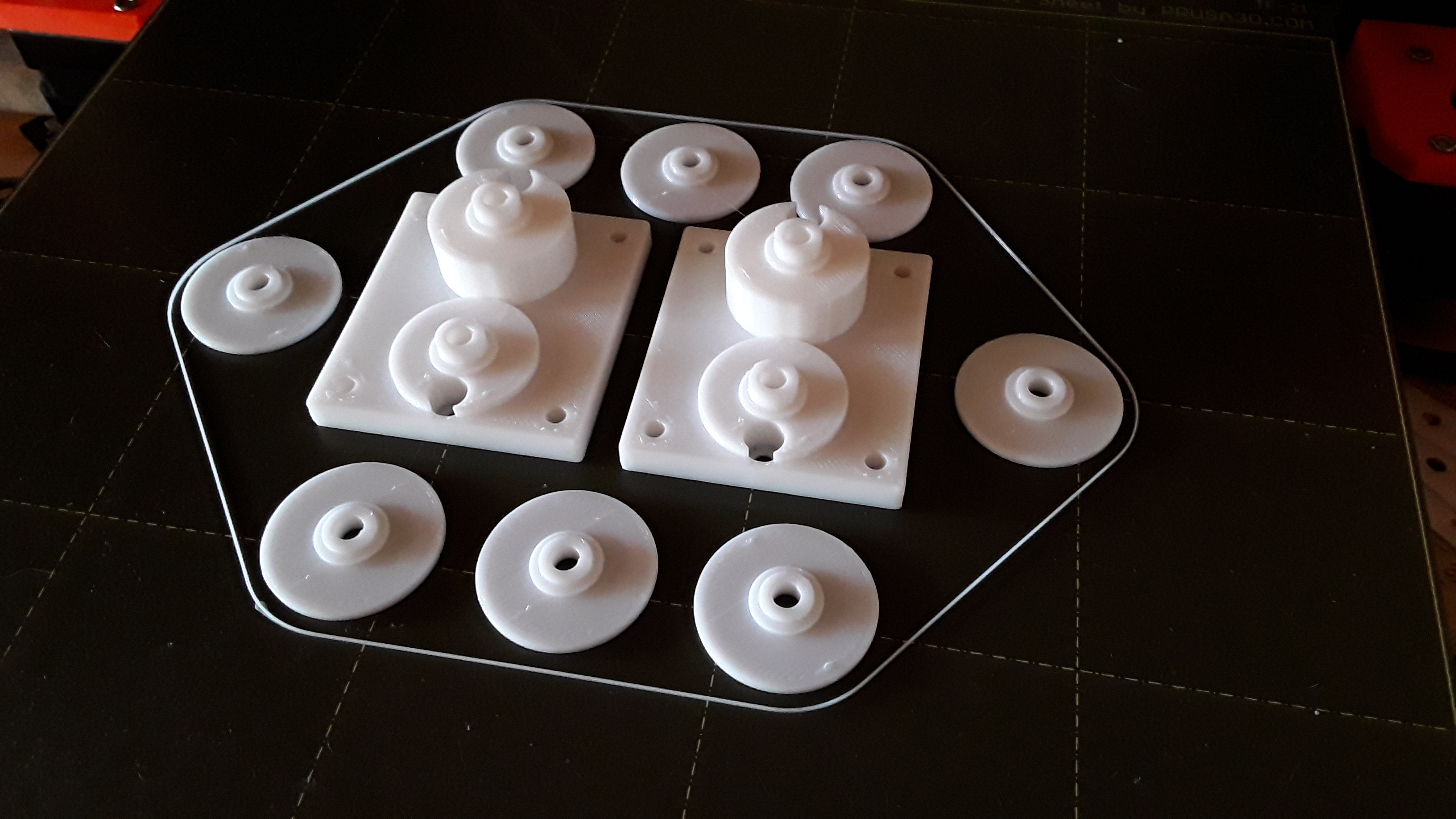
OK guys I am looking for design change advice. The core XY bearings need some work.
Here is a video where the bot is running a script that moves 10 mm/s using one motor then the other motor then both. Then it repeats the motion 10 mm/s faster. All the way from 10 mm/s up to 200 mm/s.
While you watch it here are some things I noticed.
- Occasionally you hear clicks. That is mostly from the back right bearing idler.
- At 1:53 you start to hear the left roller idler vibrating from the belts rubbing the top hubcap. I touch it at 1:59 and can feel it vibrating. (Starts at 110 mm/s)
- At 2:40 you can see the belts walk up and down the bearing
- At 2:53 and 3:15 you can see the bearings wiggle

My education is in electrical engineering not mechanical. So what do you think I should do?
- A- Make the axle inside the bearings hold them more firmly <–This one is a given but I have a few ideas on “how” (See below )
- B- Ignore the rubbing and walking belts. (Just use slower speeds 100mm/s or less)
- C- Double stack 608 bearings so even if the belt walks a little it wont rub.
- D- Make some kind of flanged idler guides that go over the bearings to keep the belt centered on the bearing. That would mean the hubcaps would be smaller so the outer bearing guide could spin.
- E- Use two 608 bearings but the belt goes between them and rolls on a thinner piece of plastic that is suspended between the two.
I am open to other suggestions. But I think I want to stick with the 608 bearings so please keep that in mind.
As for making the axle thicker so the bearings don’t wiggle. This is tricky because I want to be able to share these STL files so others can build one if they want. If I just adjust the size of the axle so my printer prints it perfectly then I will have perfect fitting bearings but other might not.
- So I was thinking about using the pan head screw to push the axle out in all directions to make it fit snug. Imagine a cylinder with a hole for the screw. Then cut the cylinder Vertically with an X. So there are four sections of the cylinder that will be pushed out when the screw gets driven down into the center. PLA might not flex well but I have been making these out of PETG and that will flex very well. The problem I see with this idea is that the TOP will be snug the bottom may not.
- Or I could make the axle slightly oversized and use a heat press method to put the bearings into place.
- Or I could make the axle not round. Make it with several small bumps (Like a smooth tooth gear) and again have the bearing get pressed on. The tips of the bumps will smash and it will end up a snug fit.
I’m not a mechanical engineer either, but my recommendation would be option D and make the axle not round.
Edit: the reasons for these choices are because they are simple cheap and take no extraordinary effort or skill to assemble… if you want others to build this those are key.
1 Like
I’m sorry, Aaryn, for the problems you are having with the idler bearings. I don’t run my laser engraver at the speeds you are running for 3d printing (110mm/s) but I haven’t noticed any issues attributable to the idler bearings on my machine. Planar alignment for each belt level is probably the key to keeping the belts centered on the bearing race.
A couple of your bearings do seem to wiggle a lot. The first thing I’d check is to insure all your bearings have minimal slop/wiggle between inner and outer races. Since you have an assortment of bearings… did you “wiggle test” them at all, before installation?
Other than that I can only offer up my bearing mount and flanges dimensions. For reference, here’s what my bearing mounts and flanges look like…
The “axle” portion of my mount is 7.8mm diameter and the inner race “flat” is 11mm diameter… and printed on my Prusa MK3S these seem to work nicely…
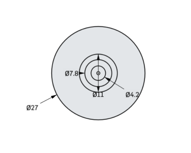
One difference I note is that I use a 4mm bolt – with embedded nut on underside of idler body-- to clamp the bearing’s inner race. As a result I can put considerable pressure on the bearing’s inner race to flat interface… and any wiggle would have to be in the bearing itself. Does the screw-thread-in-plastic method you are using allow you to put enough pressure to securely clamp the inner race sufficiently to eliminate that source of wiggle?
– David
2 Likes
My 3d printer is in an aluminum and hdpe box kinda like this. It’s loud too. They’re just big resonator boxes.
1 Like
Thanks for the feedback guys.
Excellent Point. Even if I am the only one who builds these I still want that to be a feature.
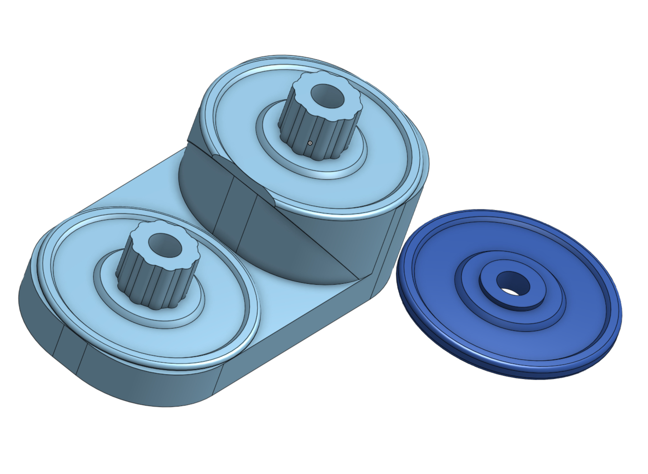
Thanks for examples. I just implemented some of those suggestions and I’ll test the results next week. I also added the round bumps to help hold inner axle. I made the Axle shorter so it will be held tighter.
Here is the new Axel and Hubcap. I hope this will Hold it tight enough to prevent most of the wiggle. I also hope that will prevent some/most of the belt walking and rubbing.
2 Likes
Well… the new parts don’t wiggle or click anymore. But the belt still walks up and down the bearing. So it still rubs at speeds of 100 mm/s or higher. I’ll have to fix that when I make the laser engraver but for this first version printer it is good enough.
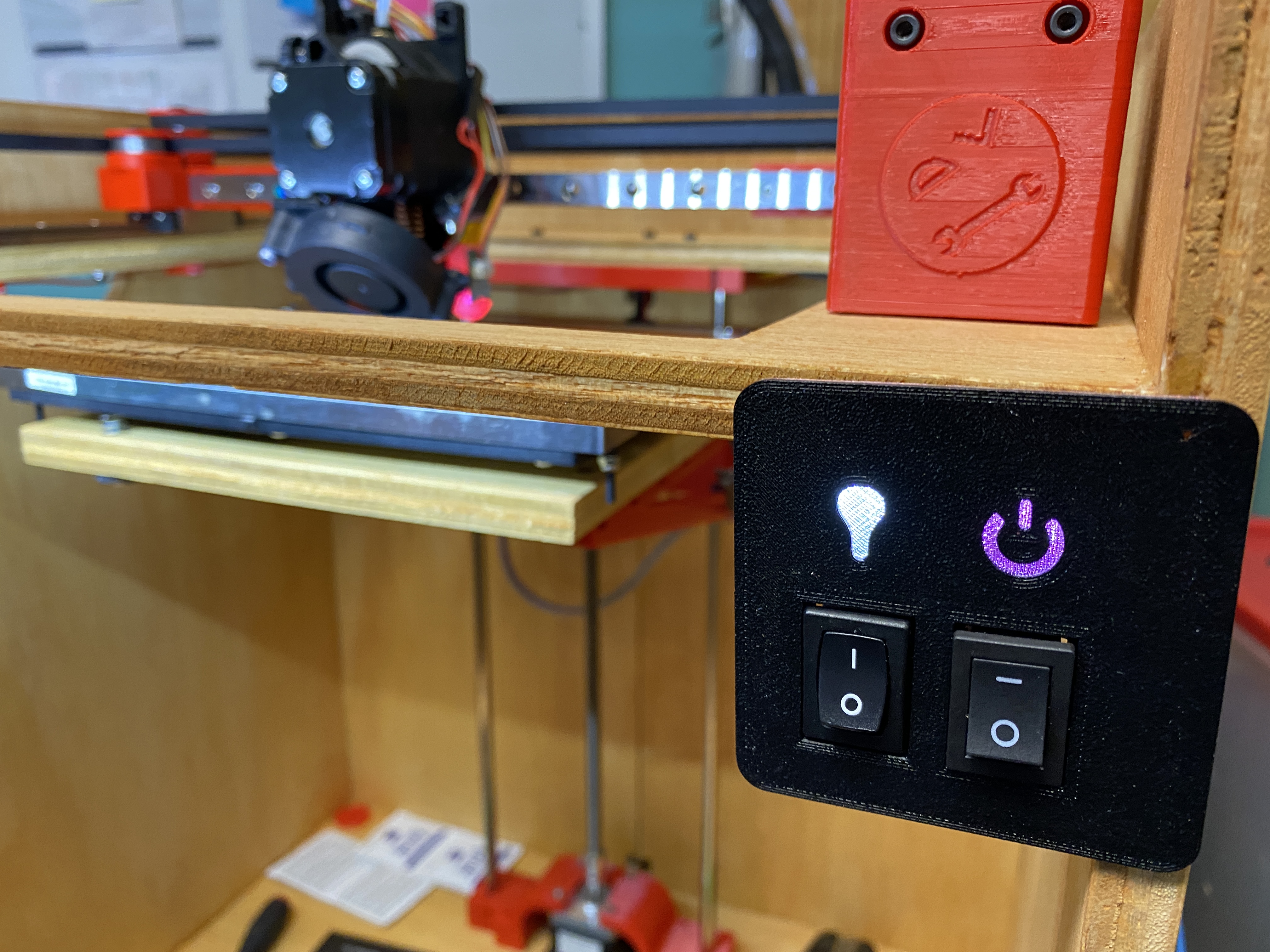
Well I also added a couple switches to the front. Power and lights. The switch plate is printed with layer color changes in mind. So others can print it by changing filament at specific layers. I thought it turned out all right.
It’s printing a Benchy and a tolerance coin. So I might be done with this one soon. Fingers crossed.
3 Likes
How are you planning on fixing the walking belts for future designs? I still like the flanged idler guides. Myself.
Yeah that’s what I keep coming back to the more I think about it. So as I build the second one that will be the first thing I try.
My other ideas are…
- double stack the bearings. That would be heavier and may not completely solve the problem.
- use two bearings with a rod between them. The belt would roll on the rod between the bearing that would act as guides. Heavy and difficult to assemble.plus the belt would still rub on the bearings.
- use other types of bearings with metal flanges. I would rather not. But that may be my last resort.
- Try to better align the belts so they don’t walk up/ down. This would be some really tricky tuning that might be difficult to repeat or teach. But I can see where my lower belt (the belt that is rubbing) clamps onto the tool carriage it is at a slight angle. That is probably contributing to the problem. I’ll try to fix that but I don’t think it will do much.
Yeah ill be honest I don’t like any of those other options except maybe better aligning the belts, but I agree that It will be hard to get them, and keep them just right.
You could always put the flanges on the axle and hubcap… in fact you could almost fully cage in the belt with them if you needed to… then your not printing extra parts and people don’t have to try to push plastic pieces over the bearings.
1 Like
Glad to see this working for you. I think I want to rebuild mine with a MUCH smaller box, lol. I’m gonna put the motors outside like you did and shrink everything down. I really thought I needed more run to get everything assembled. But jeez, my list keeps growing. Now that my 2x4 primo is doing its thing, I can see potential for the teeny tiny to grow up a little. And I want to build a print NC just because. But not until after I try to put my diode on a zenxy that I can stand up on the wall. All of which waits until after I get the speed control for my 660. And that’s just the cnc related projects!
Heck, I might even just get some rails and build a Timber Bot!
1 Like
so when are you going to post the STLs so i can start looking at building one? XD
1 Like
STL! STL! LOL!
Guess I need a complete sentence to make the post…
3 Likes