The bearings of the usual steppers are, if at all, optimized to cope with lateral forces. Coaxial forces, specially higher frequency and energy pulses lead to accelerated wear. Dual bearings (preferably for coaxial loads, but even I haven’t gone that far yet) are better than a single one which is still better than none at all (like on those cheap filament melters).
![]()
![]()
![]()
![]()
![]()
![]()
![]()
![]()
![]()
![]()
As mentioned some weeks ago I have added an accessories set for the standard PRIMO
1 Like
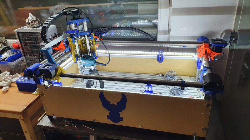
In the last months I have modified and added some stuff:
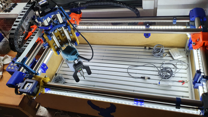
- I have closed the PRIMO
- Spent some LEDs around
- Inductive Switches now work with AutoSquaring, that’s fantastic
- built new shield with wireless controller (bought a kit)
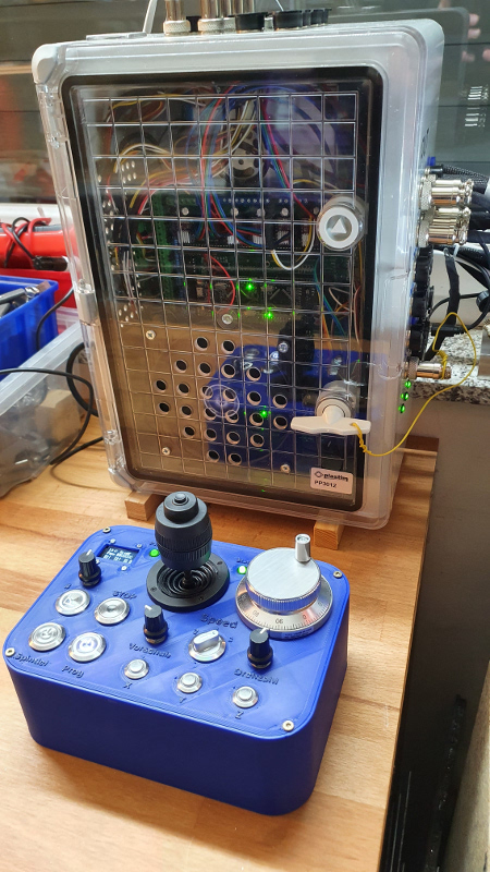
New shield with the wireless controller
Inside infrastructure with power supply, boards (with 3 Arduino Mega), cabling system  with all the inputs and outputs, fan (front door) which is controlling (speed) from the board and and and.

And also the wireless controller has quite a lot of cool add-ons:

- Display for fan, autosquaring, temperature
- Autosquaring button plus poti for speed during prozess
- Stop button (steppers without current)
- Starting spindle with speed poti
- Programm start/stop
- Feedrate poti
- Joystick 4 axis (x-, y-, z-axis plus Zero-button)
- x, y, z-button to control the steppers
- additional wheel to control x, y, z-direction with high sensibilities.
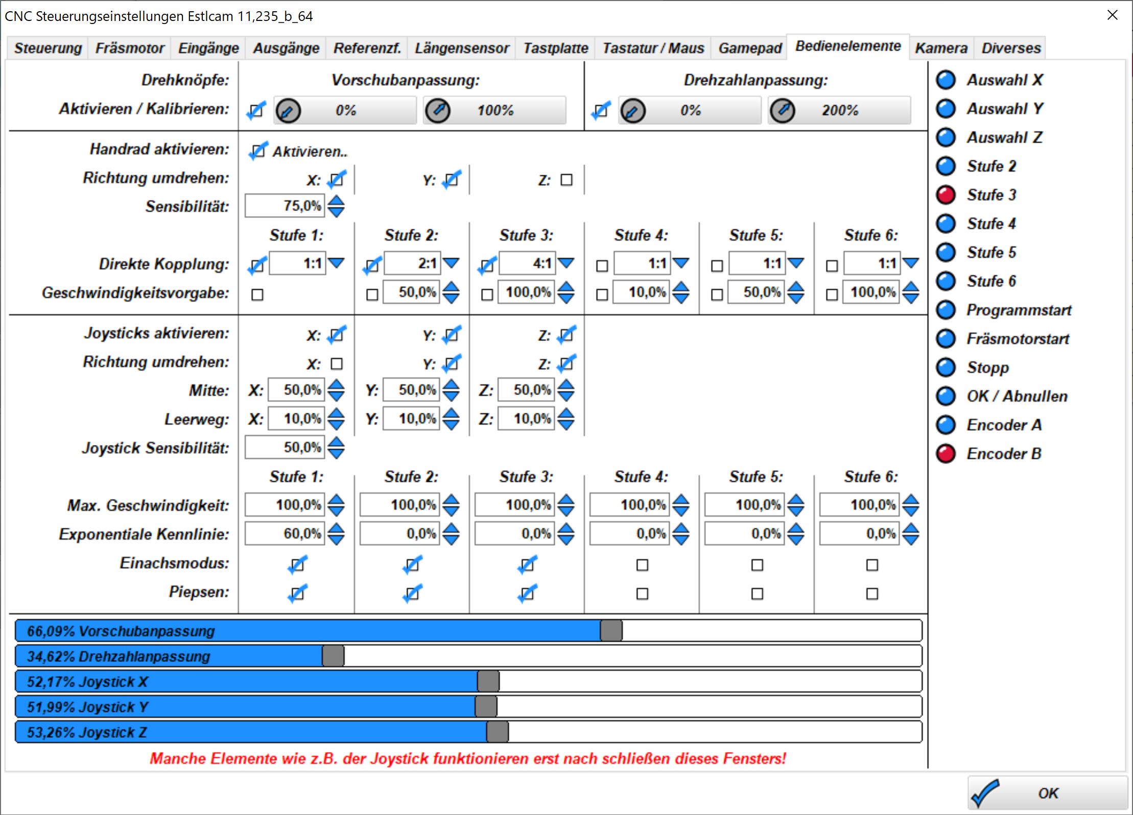
And in Estlcam all these functionalities are usable/configurable
6 Likes
Man, this is a long Z. 
Mine is longer 
 … have a longer one!
I promised to publish some infos regarding the levelling of the aluminium bed. @Bigchepin
I think it needn’t to be commented 
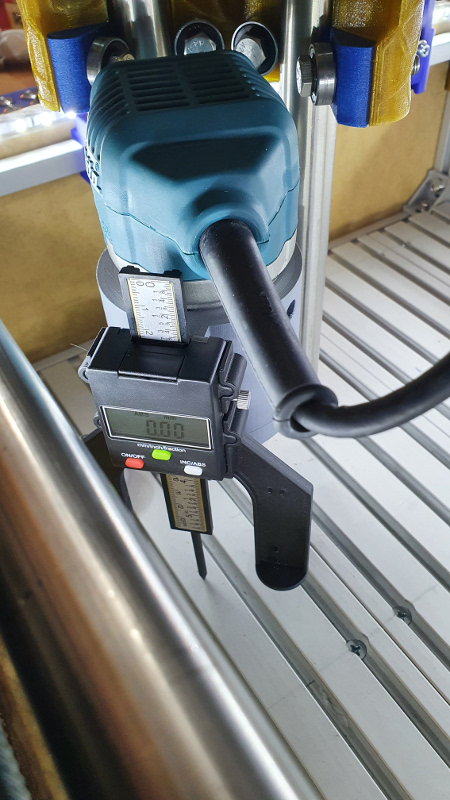
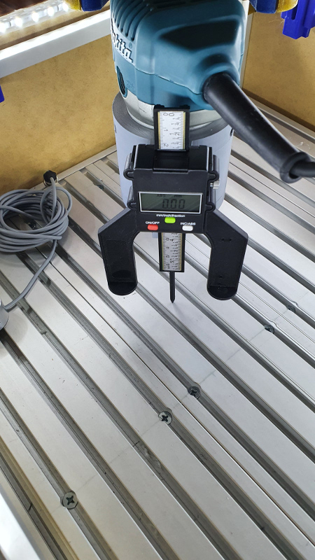

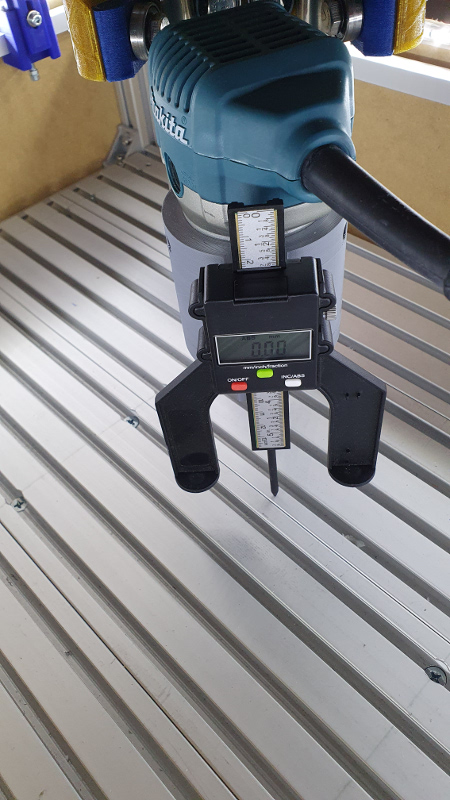
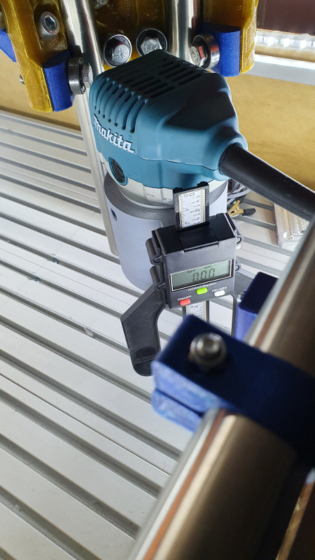
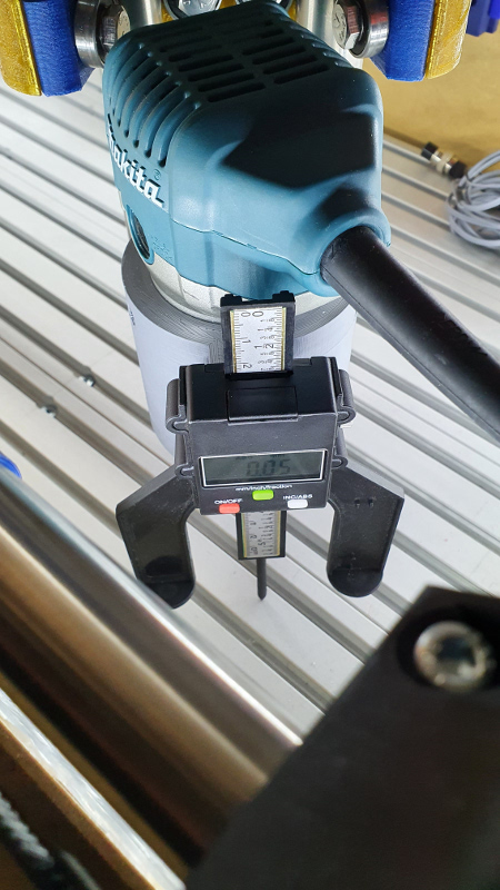
… but to be honest I was really surprised by myself to get these results. Only in the right angle of the bed I get 5/100mm tolerance. On the other steps exactly 0!! That’s OK!
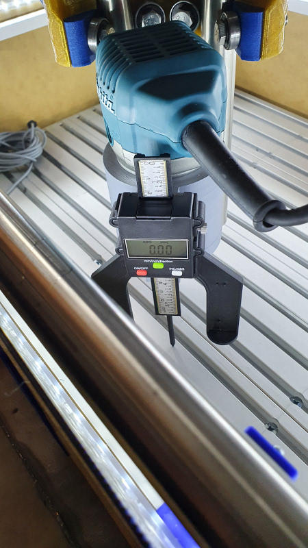
On the Z-axis I get tolerances of 1/100mm per 1cm height.
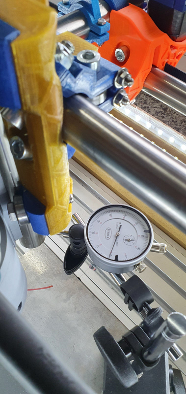
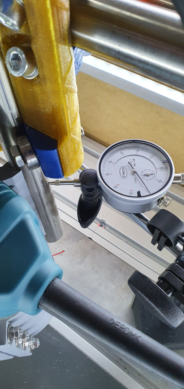
Here I measured the height of 10cm and I got 10/100mm tolerance. That’s OK from my prospective.
And for the squaring I have designed a new tool to adjust the autosquaring feature of my controlling unit.
I printed a tool to fix the pipes of the x- and y-axis to adjust the inductive switches.
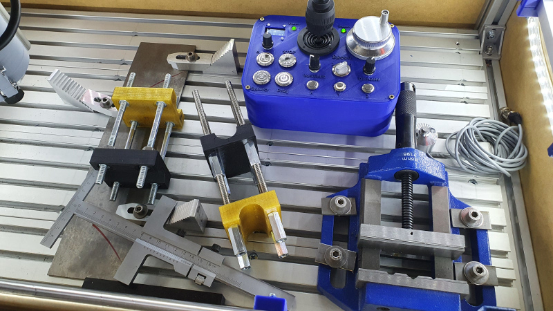
The tool can be exactly adjusted with thread rods (4 per tool). In this way you can exactly adjust both tools to get the pipes in parallel.
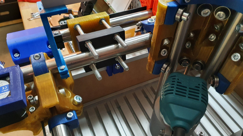
To place it in the position without moving I used the stopper to fix the truck completely! (shown in the foto above)

Placing the tool on both ends of the axis you can definitly position the end switches (in my case the inductive switches).
Repeating it on the y-axis you get the switches exactly positioned to use the autosquaring funcs of the controller. It works really well!!
2 Likes
Hey that’s a great idea. ![]() Your build is looking great! What was your leveling plan if it needed it?
Your build is looking great! What was your leveling plan if it needed it?
Also I love the wireless controller. Are you going to do a separate build topic for it if you haven’t done that already? I’d like to build one eventually.
To be honest, there was no plan. The levelling result was based on a couple of things:
- very precise cutting of the aluminium profiles of the bed (also to get a real rectangle structure), but also the feets where the PRIMO is mounted on.
- adapters for the corners can also be positioned/and adjusted to move the corners up or down. But it wasn’t necessary.
- construction: the bed is mounted on the frame. In my first construction (with Burly) I mounted the bed inside the base frame and it wasn’t adjustable
Based on this “feature” I can adjust the bed in an area of 1/100mm - 1 mm. - and of course time to adjust the bed
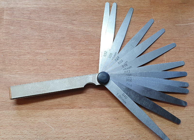
And to get it to the result you can see above I used a tool that typically I use for my motorbikes, to adjust the valves of the cylinder head. ![]()
No problem, I can do that in the next couple of days, but it needs to be said, the wireless controller works only together with the controlling unit. Of course it might be, that I you could get it running with another board based on Arduino but IMO it would be necessary to write a sketch for Arduino to get it running and connected.
1 Like
Hallo @DJPicasso
ich baue auch gerade einen MPCNC Primo und finde die Idee, Aluminiumprofile als Rahmen zu verwenden, einfach genial. Könnten Sie eine Step-Datei von diesem Adapter hochladen, mit der Sie das Aluminiumprofil mit dem Eckboden auf Thingiverse verbinden können?
Danke und beste Grüße aus Österreich
Paul
Hi @PaulBrunnmayr1234
parts are downloadable from Thingiverse. If you will have a look more up you will find the link.
Hello @DJPicasso
I’m currently building an MPCNC Primo and I think the idea of using aluminum profiles as a frame is simply brilliant. Could you may upload a step file from the Corner_Leg_Frame30x30_V11.stl so I can chnage something on it? I need just the dimension to make a own part but it is pretty difficult for me to measure it. I just use it for my selfe and of course I dont put my or your version on thingiverse or any simelar platform.
Please write to me if it is not Ok for you to send it to me. When its okay for you i would be very happy if you send me this file!!!
Thanks and best regards from Austria an sorry for my bad englisch😅
Paul
/edit: einfach draufklicken, da sind alle seine Dateien für den Alurahmen.
Hellos @Tokoloshe
Are there also files which I can edit for example in fusion 360?
Best regards
Paul