Hi all,
I’m new here, having just finished my Primo build after starting it 12 months ago. Also have a bunch of DIY 3D printers and a 3018CNC that I’m trying to make a bit more rigid, but that’s out of this scope, just for background that I have some mechanical aptitude.
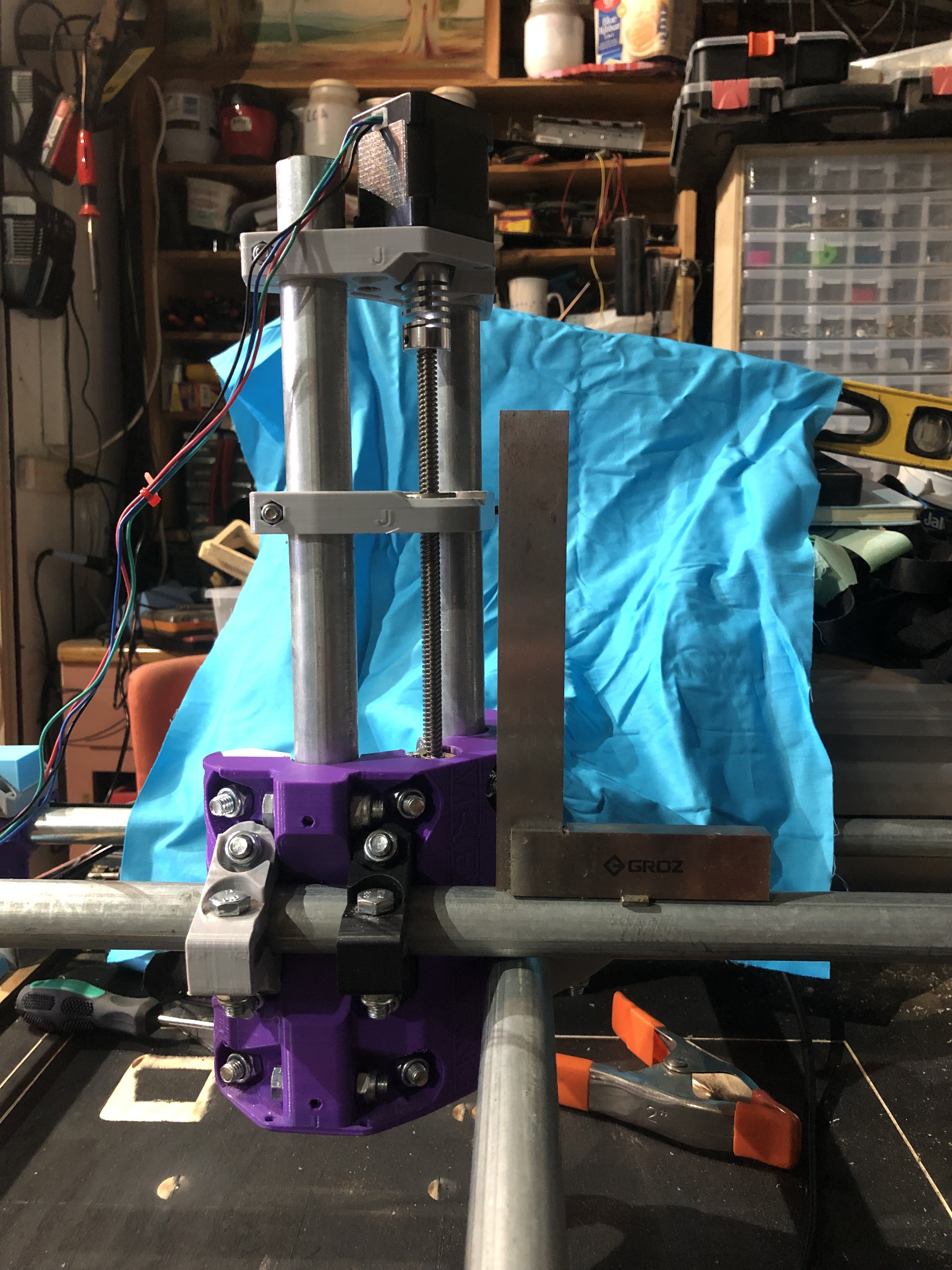
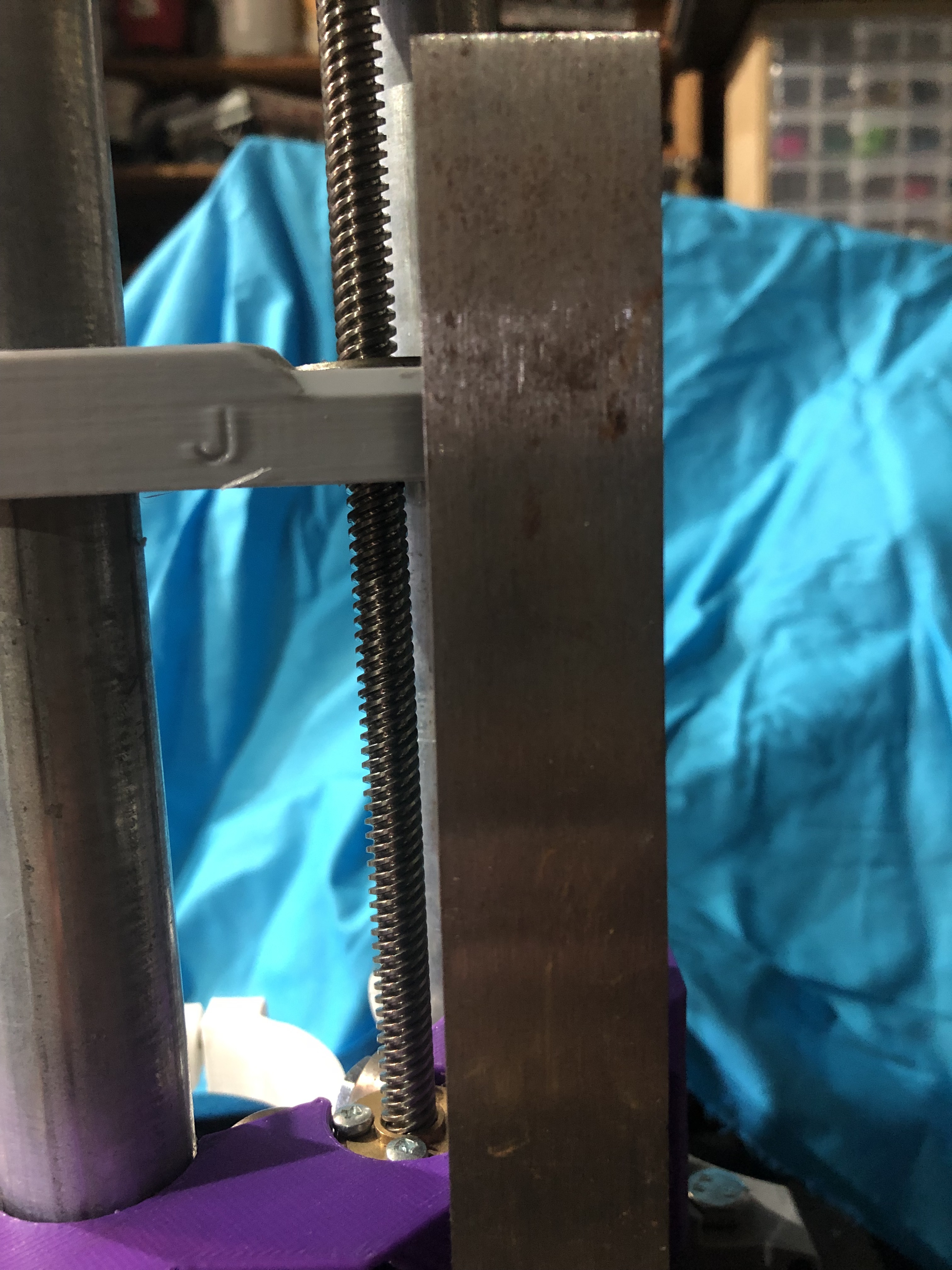
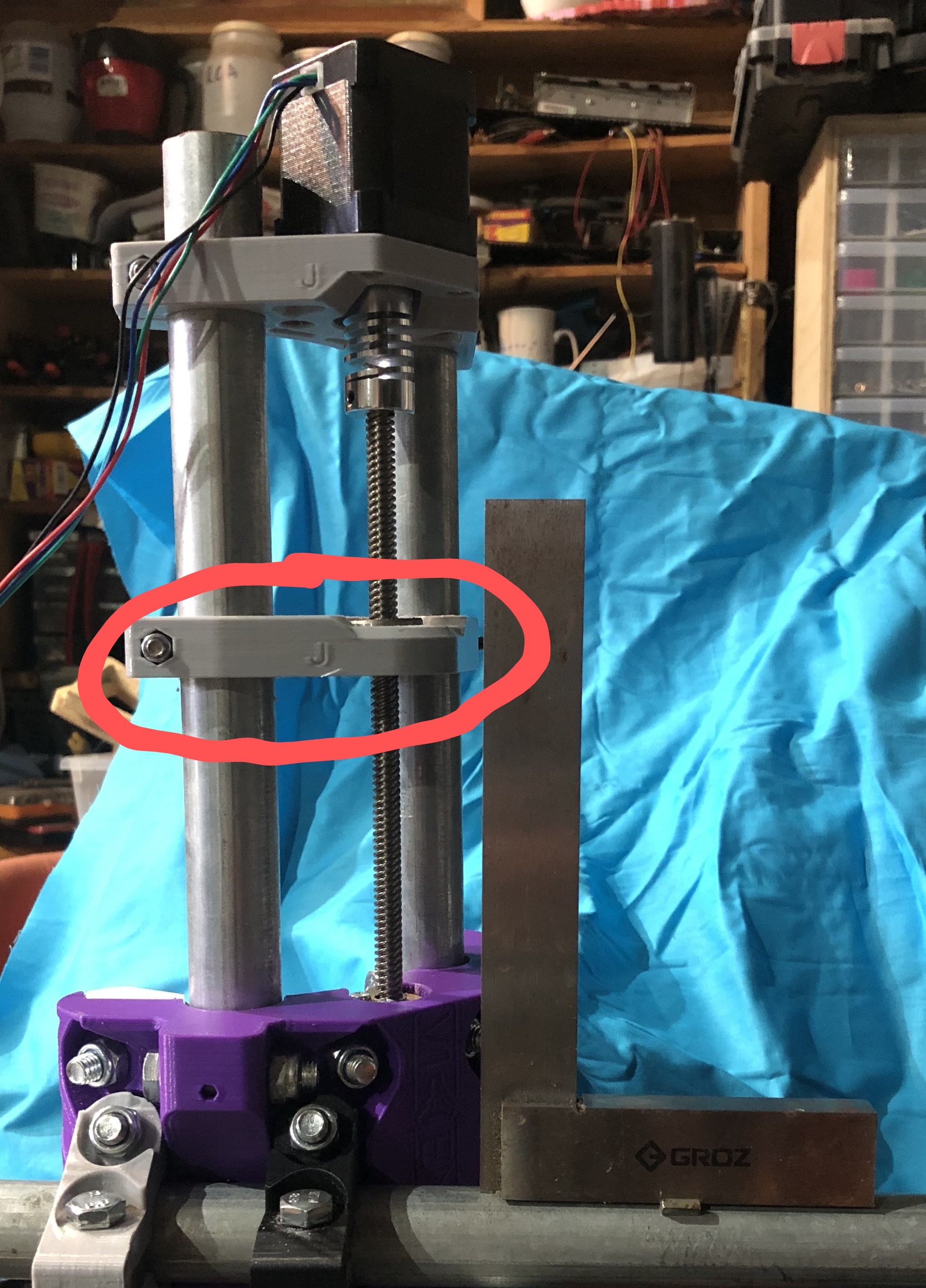
Issue: The Core currently leans towards the front, such that a 16mm mill requires about 0.8mm from first contact with the work surface to contacting its other edge.
With NO Core clamps in place, and the core held against the X-Y junction (where it would be clamped) it doesn’t quite sit right. Whilst the rail-groove will site nicely against the left-right gantry tube, the front-back tube isn’t quite aligned, so when the clamps are added, it pulls the core down to the front.
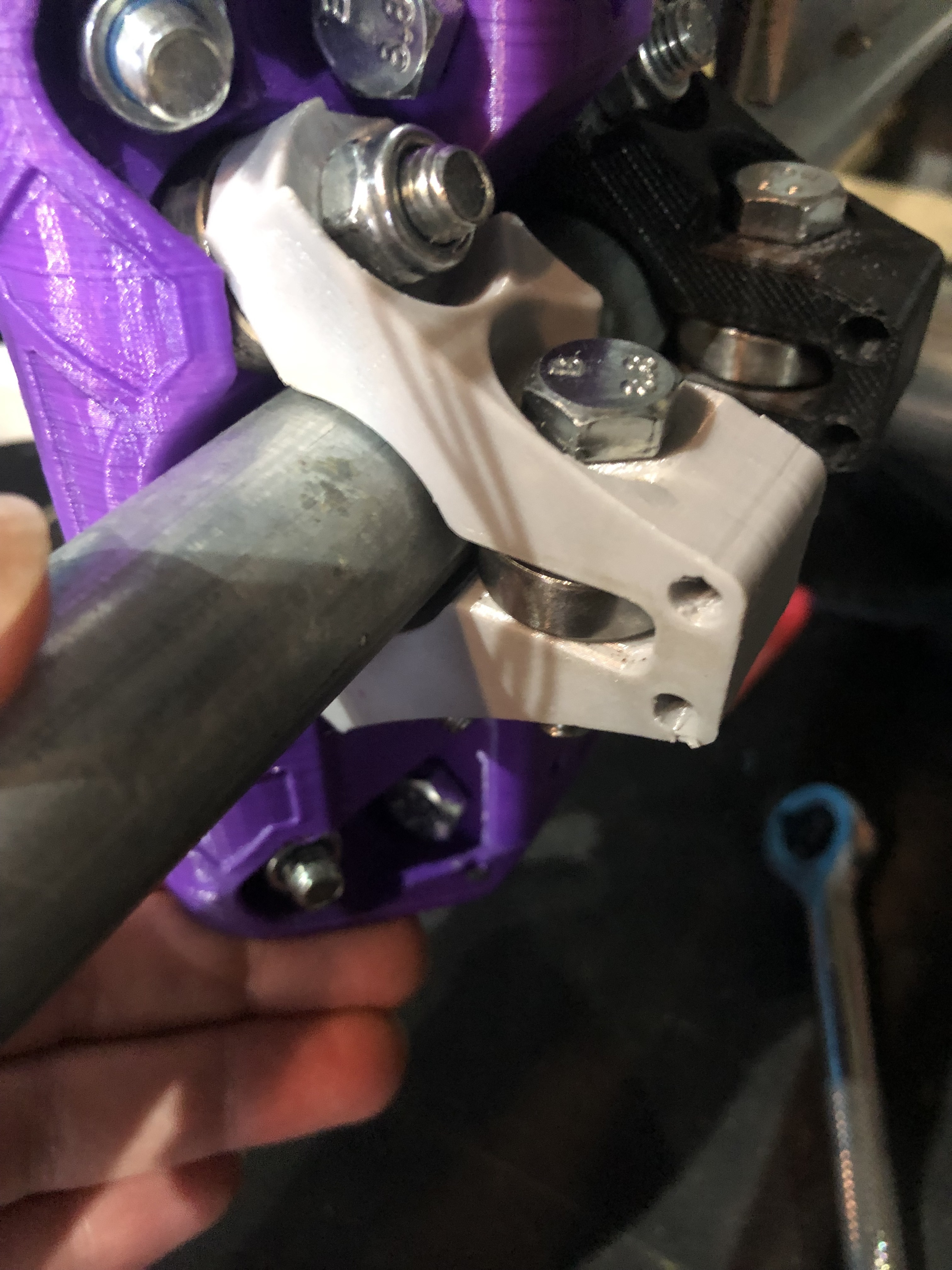
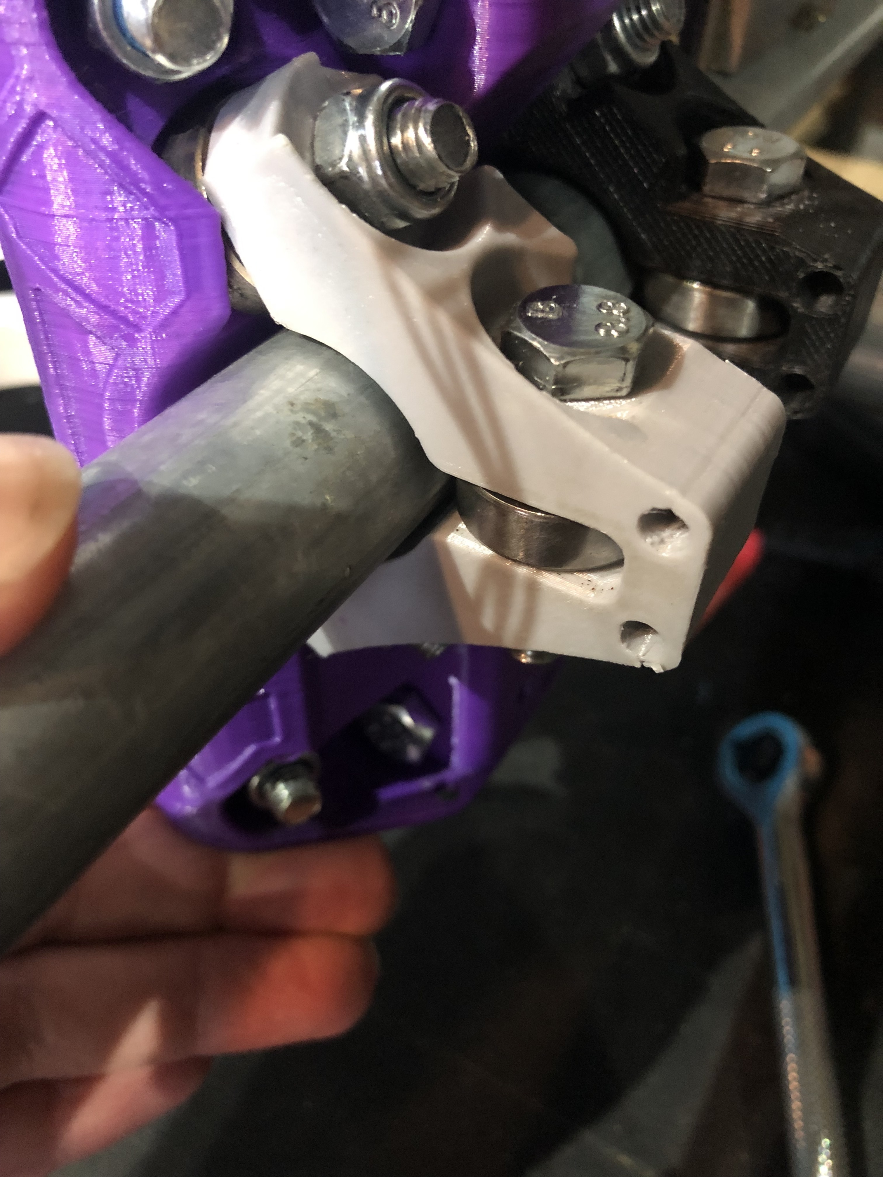
To test this out, I used a ‘saw drill bit’ 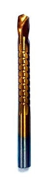 (see photos) to carve the front core clamp holes a little further down and this managed to get the core pretty much plumb, but installing the rear clamp then pulled it out again. It looks to me like either the two gantry rails are too close together vertically or one side of the core sides has the rail and/or clamp holes too high.
I know a few users have reported their core not fitting well and I’ve read through a bunch but not found a solution that works on my setup. All axes are level otherwise.
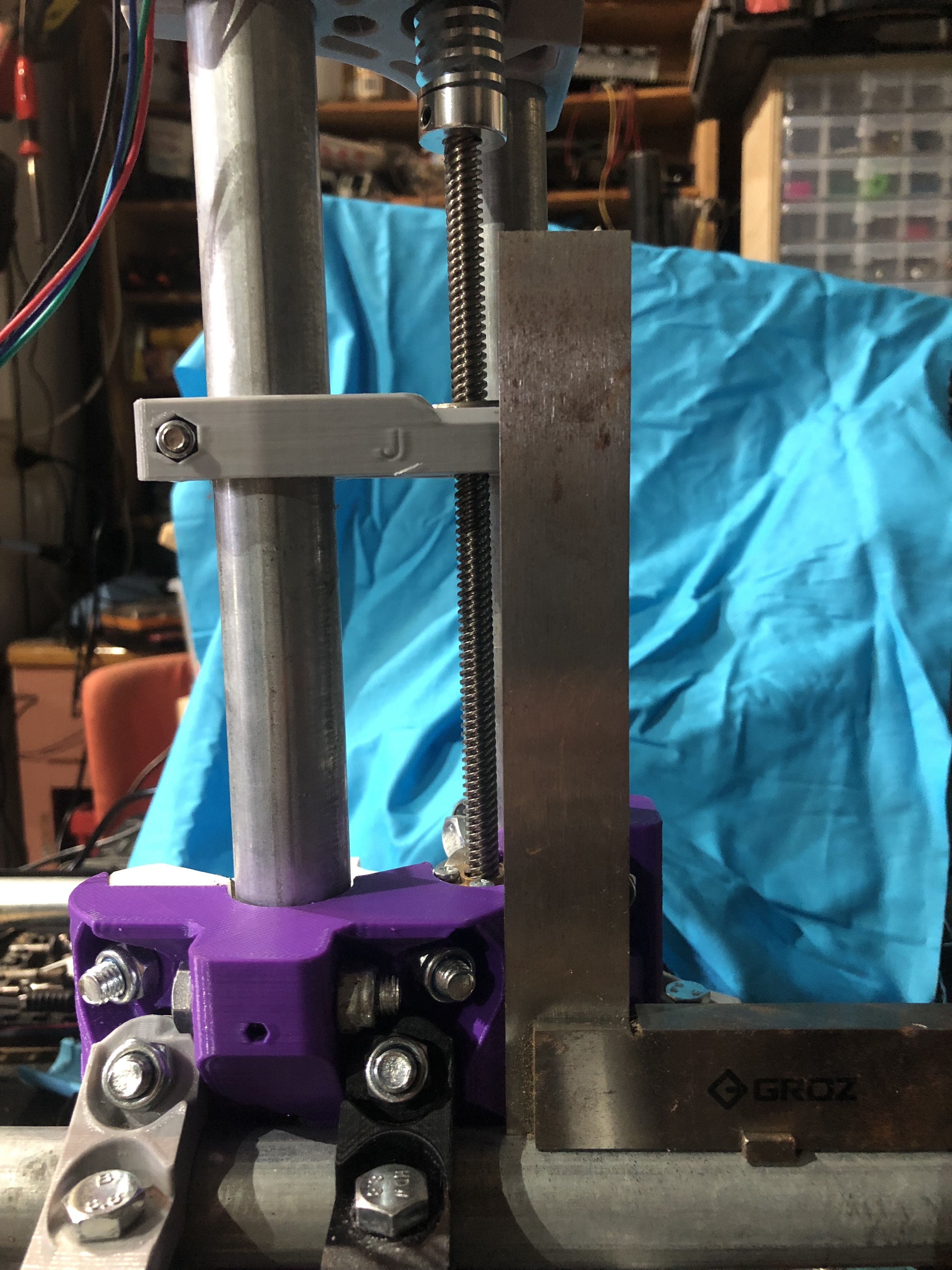
Other measurements (25.4mm OD tube):
Top of top tube to bottom of bottom tube: 52.4mm
Gap between tubes: 1.6mm
Distance between tube centres: 27mm
X&Y rails are ~540mm of exposed tube, between mounts.
Parts were all printed by me and seem to be to spec (the core height measures within 0.2mm of what I measured in the STL, once imported into FreeCAD). Printed using J build downloaded in August last year, VER1 editions of Core and clamps - same files as currently on Thingiverse.
Tube is 25.4mm galvanised, measured close-enough to round to not make this difference and tested at different rotations.
Bolts bought from a local supplier through eBay - straight section of shank measures 7.8mm
Bearings as above - measurement of exterior and internal bore are to the published spec for 2RS bearings.
For now I’m just going to drill-out the other holes to try to level it.
Thanks for any suggestions,
Simon