New build in Clapham, North Yorkshire, UK

As I knock one item off my ‘todo’ list, more seem to pop on.

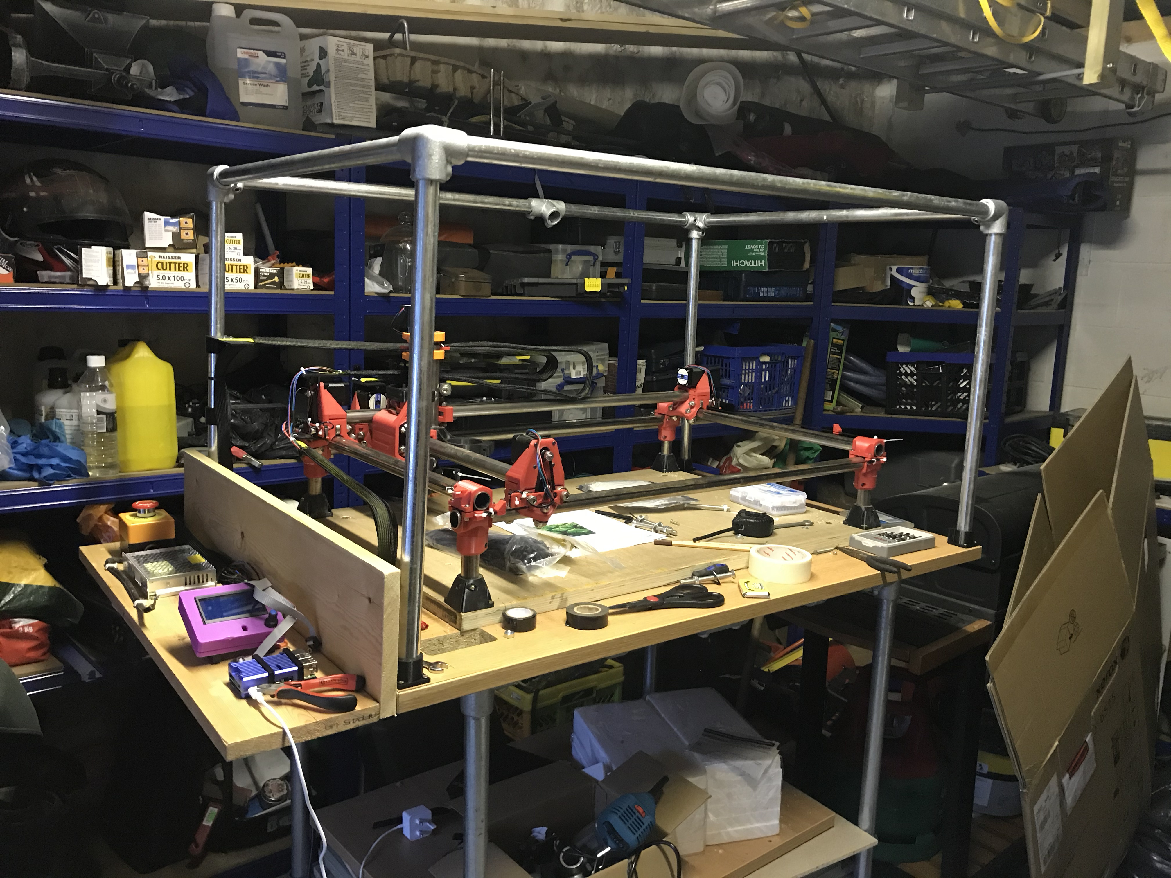
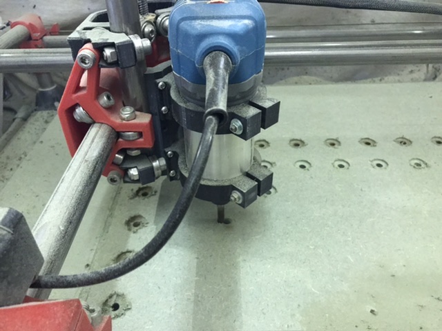
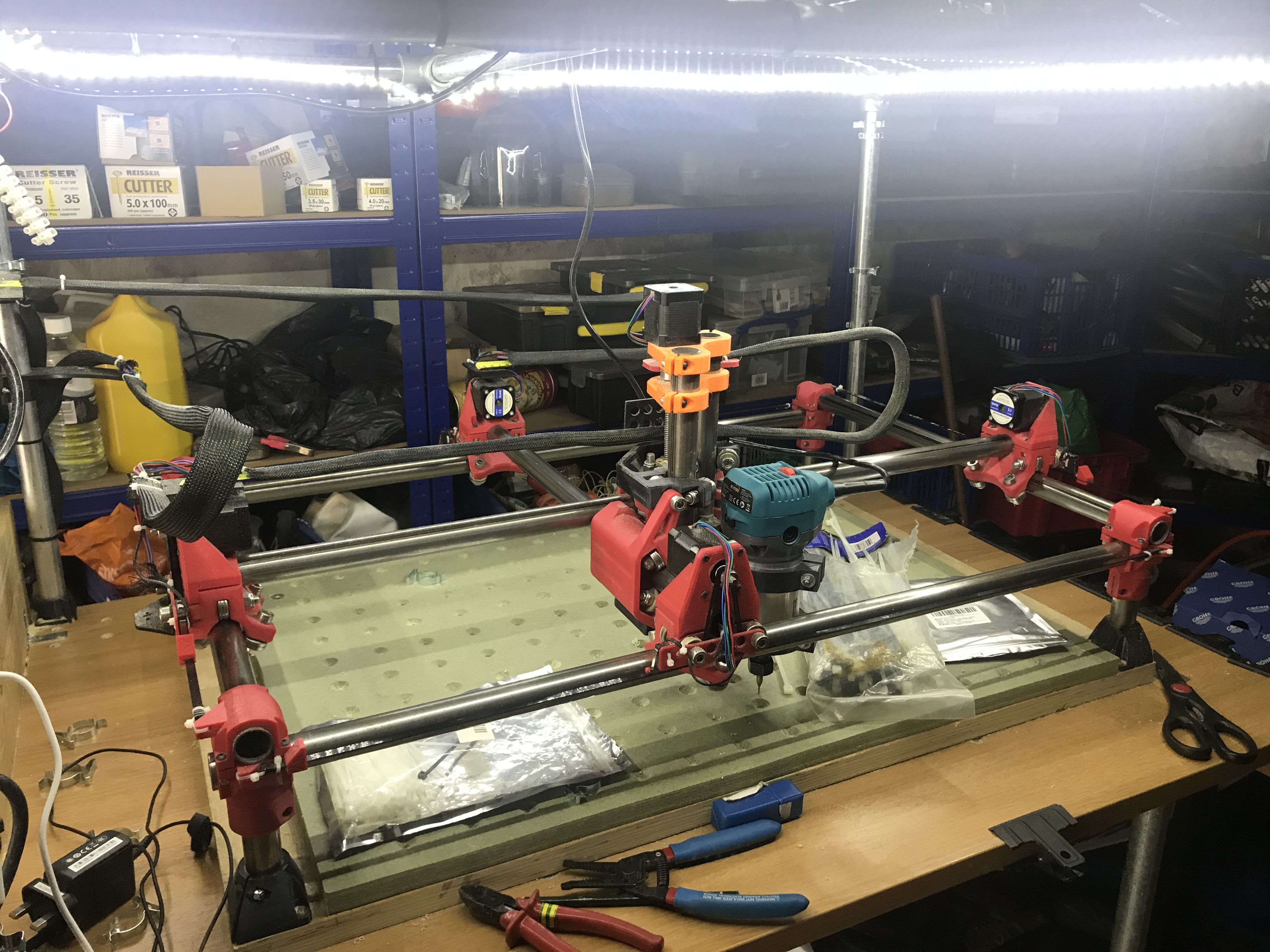
I have already seen that the bed of my MPCNC is not level, though it’s pretty flat.

If I look from bottom left (0,0) towards top right, it was clear that a pen that was lightly touching the bed, but as it went to max X and max Y (top right), it was around 1mm to 1.5mm off the bed.

So I thought I’d measure what was out. Simple enough job…?

So I pulled out my cheap digital caliper. I only trust these to 0.1mm as they were exceptionally cheap about 10 years ago, but that’s enough margin for me.

The first problem is that they aren’t designed to work the way I want them to, I want to measure the distance from the bed to the 25mm tube. The calipers are designed to measure stuff inside the jaws and there’s no nice long flat level edge on the top or bottom of them to rest against the bed. So I thought I’d actually design something in Mac FreeCad to hold the head of the caliper in a stable position and at right angles to the bed. I’ve never used anything but Google Sketchup for design and that was 6-7 years ago, but it can’t be that difficult, can it> Well, I can now scrub Mac FreeCad off my list of well designed and stable Mac products. After the 5 or 6th crash in an hour I gave up. It was just impossible to keep it going.

So I then moved to Fusion 360, it’s free, I’m not breaking any license terms as my income from this is significantly less than £0 to date. It then transpires that you need to have some sort of brain operation twist your brain through 90 degrees to get the hang of it. All I wanted to do was draw a simple block, put two screw holes in it and cut a T out of it. Six hours later and feeling like I’d reengineered the entire Apollo space program, I had two blue blocks in my hand, that 1) fitted my calibers 2) were stable.

I look at the simple (and it was simple) block and look at what Ryan has engineered for MPCNC and I want to cry. Six hours to get two blocks of printed plastic (and eight blocks thrown in the bin as they were wrong). How the devil did Ryan design the thing of beauty that is the Z gantry? Was there a crossroads at midnight , a bloke in a black hood, animal sacrifices and Robert Johnson involved?

Anyway, I now have a device that I have designed and printed by myself and I start to measure my MPCNC. I realise that the absolute numbers are irrelevant and that it’s the difference that’s important.

So here they are:

I have tried to keep this simple as there are lots more measurements I took :slight_smile: I have started building up a mesh. You’d never guess I love data…

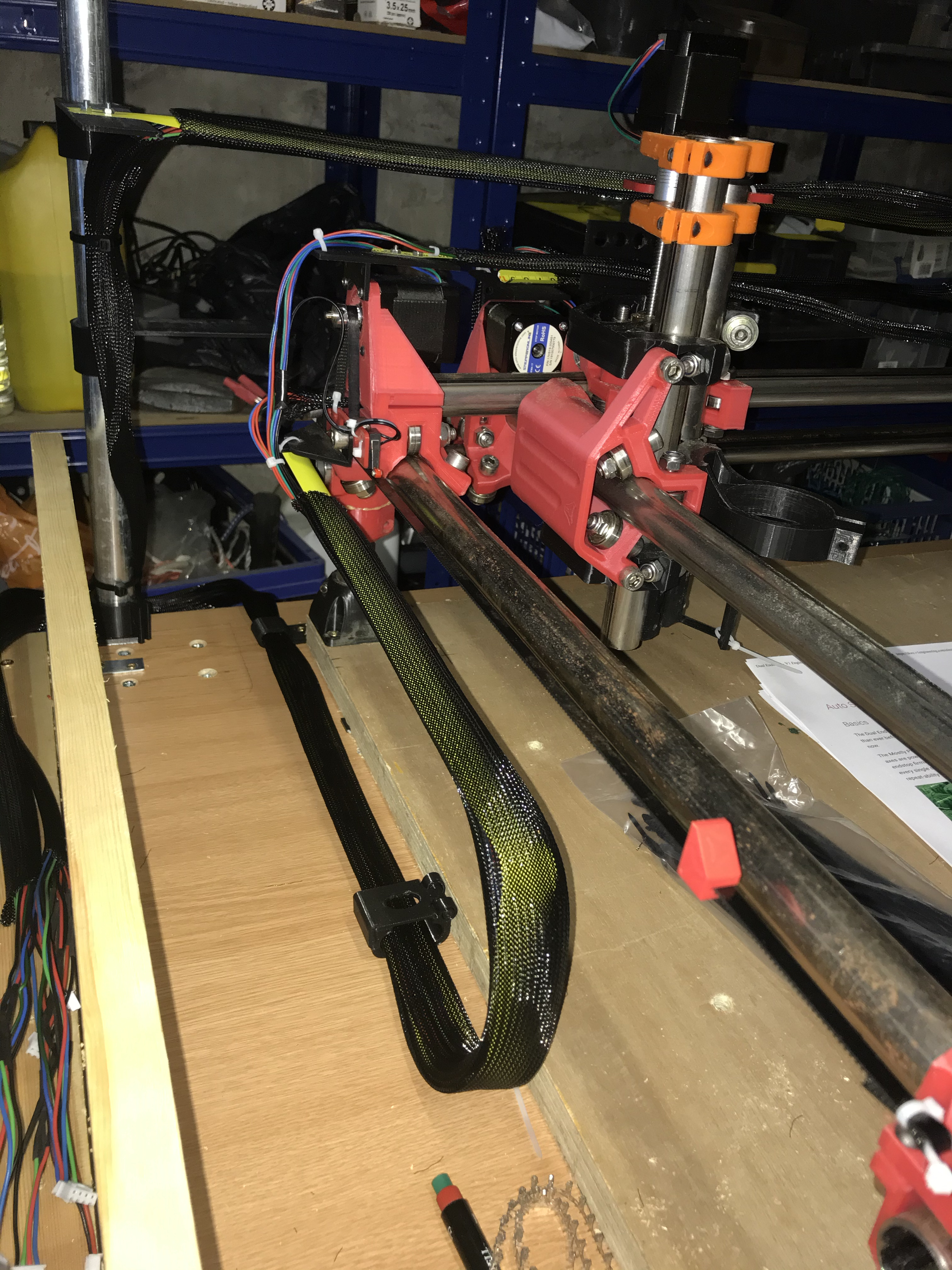
Bottom left (0,0 ish) is the datum point. What I am measuring here are the Z values, a +ve Z value is out of the bed and up in the air and a -ve Z value is towards the floor. This matches the Z axis movement in Marlin.

The numbers back up what I thought. The gantry is very slowly moving away from the bed as it moves along the X and Y axis.

Now there appears to me to be two solutions:

  1. I run a small planing run across the spoil bed (not shown) to level it.

  2. I shim the stepper motor mount points on the X and Z axis tubes that hold the Z axis gantry by a small amount so they are trued.

Since I have to do point 1 anyway, is there any value in shimming the stepper motor mounts. It’s easy enough to print a couple of 0.6mm and 0.3mm shims to level things up, or am I worrying about things that I should ignore.

Views and comments welcomed.

Rob

1 Like

When you cut through the board, into the spoil board, you should cut a few mm into the board. That is no big deal, and it will easily consume these <1mm differences. If you make a rabbet or a dado that doesn’t go all the way through, you’ll probably want a bit of tolerance built into that too.

If you are using a v bit, the the error in Z translates to an error in width. That is a bit annoying, but if you are using a small area, you can set the Z there, and use a sharp bit. You won’t notice it.

If you need more accuracy than that, you can surface the spoil board (which is 1 above, I think). But I would avoid doing that for a while. Because it will account for everything that affects the height, and you don’t want to do it too many times. If you use your machine for a while, you can find all the other things you may adjust that affects the height, including shimming the corners, break in, whatever. Then when you surface it, it will be more stable for longer.

1 Like

@jeffeb3

Thanks, for the update. I’ve yet to turn a spindle in anger :slight_smile:

However I don’t expect to use a v slot, but rather a square end for the bit so that probably not an issue at the moment.If I do engraving, I can see it’ll be a problem unless I setup a spoilboard,.

I’ll not bother shimming it and will see about attaching the router (finally turned up), screwing a spoilboard down (and recessing the screws) and then running a 25mm thingymajig across it to get rid of the level differences. I have a faint idea what to do, what could possibly go wrong :astonished:

Rob

[voice person=“George Takei”] Oh, my… [/voice]

“Alphabetically, or in likely order of occurrence?”

“There are some sentences [you] should just stay away from.”

“Whenever you ask that, my tail gets all bushy.”

I could have written:

“I have no idea what I’m doing with very sharp objects spinning at 15,000RPM, 240V electricity using highly complex IT software to control the speed and direction on a plastic machine I built myself, where the last thing I built out of plastic was an Airfix 1:72 scale Battle of Britain Spitfire aged 10 3/4. What could possibly go wrong?” Technically that’s just as accurate :crazy_face:

I have five more spoilboards to use after this one.

I will do a number of dry air runs just to see what happens. I might then connect up a pen to trace it and then and only then connect the router. Then “What can possibly go wrong?”

Rob

1 Like

It can be very satisfying, and confidence boosting, to try the HD foam too. The pink/purple stuff with small bubbles. No load, but it holds a very crisp edge.

1 Like

Hey Rob looks like you have been having fun. You make me want to check my stepper wiring to as i think mine could be better. Im using cat5 and two strands per wire. More than one of my wires ethernet connector have broken tabs so they dont click in and become captive. Its entirely possible that my phone holder wasnt wide enough due to this. Also be aware in fusion360 of the default which leaves positive stock for a terminating extra finishing pass that confused me too. Thats if you use fusion to make you milling code.

As for the corners i used an extra unwanted corner top print to standardise the gap between the corner bottom and corner top. That has got me so much closer to leveling the four legs. You could design and print one specific to the height you want. I had to of these extra corners due to overprinting the wrong mirror image of a corner and also printing one with insufficient fill for my hulk rage when tightening the belts.

Anyway its looking brilliant. Like the scaffoldesque table. Also my wife had a chuckle about the CFO comment. Sounds about right.

@whereswally606

Things are moving on and for some weird reason in the right direction, at least for today.

I did think about using Cat5 or Cat 6 cable but was unsure whether the cables were thick enough and whether solid core would stand repeated (gentle) bending, so went with 22 (24?) SWG.

My knowledge of Fusion 360 is as an utter novice. I used Fusion to make the digital caliper mount and it was a long and painful experience. You will note the slab sides to everything. I wanted to make the base thicker than the top but couldn’t work out how to join two bodies/components/sketches or whatever is needed to do this so ended up with a rather neo-brutal design. Not through choice, but from necessity. Every time I do something new, I have to learn a whole new skillset. My intention is not to use Fusion for milling but I will generate gcode from an home grown application. Whilst that sounds more complex, the use case I have in mind for the MPCNC makes this possible. I’m used to writing code to do what I need and have written compilers, virtual machines and the like, so generating fairly simple gcode is not that big a deal. I’ve got the front end partially done, buy needed the MPCNC to test things out manually. Once I’ve done that, I can join my front end software and the MPCNC together and send down my gcode.

I’m going to ignore the small mm differences in the height for now. A spoil board will remove those issues, though a little part of my brain will nag me over the 0.75mm difference, but I’ve learnt to ignore that little chimp on my shoulder :slight_smile:

Next things to add are:

  1. I still haven’t finished the end stops. I keep getting pulled into other things :frowning: It’s partly to avoid using those fiddly little connectors for DuPoint and JST fixings. Still waiting for the scars on my fingertips to heal.
  2. I’m waiting for some 65mm M5 bolts to fix the Katsu router to the gantry. I printed out the mounting brackets but didn’t realise I didn’t have the right length bolts. I wanted a Makita but thought I’d try a cheaper version and see how it works. I’m not machining anything heavy though so the Katsu might be suitable.
  3. 5V buck for the Raspberry PI. Simple lack of enthusiasm.
  4. Z axis wiring using the expandable tape trick.
  5. Tidying up the X and Y axis wiring after they come out of the drag chains. I may move to the tape measure wiring if that works.
  6. Spoil board levelling.
  7. Spoil board M6 T nut mounts.
  8. Trying to learn about EstlCam. I have it working under VMWare Fusion but might need to move to an old and cheap Windows laptop.

The list is going down now :slight_smile:
Rob

My CNC is slowly moving in the right direction.

  1. I have mounted the Katsu router (£30/$30) to the gantry and turned it on. It seems to work OK.
  2. Finally managed to bridge the networks from my office to the garage so I can easily send work to the Raspberry PI. Repurposed a Black Knight router and that was hard work.
  3. Made a mount in Fusion 360 (woo hoo!) to connect a tape measure in a nylon braid to the MPCNC. I am sinfully proud of designing, making and printing something like this. It looks quite good and works well.
  4. Got EstlCam working under VMWare Fusion and got it to send out the gcode to do spoil board levelling. It only sends output files with .nc as the file extension, which means I have to change it to gcode to upload to Octoprint. Anybody know if you can get EstlCam to change that?

So good progress, until I started to level the spoilboard. Wow! What a lot of dust. The levelling lasted around 10cm before I said enough is enough.

So as is normal two steps forward and one step back. I now have to build an enclosure for the board as the dust makes it impossible to use. Have ordered the parts but not here until Monday next week, rats!

So will use the time to

  1. Move the X and Y axis to use the tape measure trick (there must be a better name).
  2. Wire up the end stops
  3. Get some hardboard for the enclosure
  4. Design some end feet for the enclosure.
  5. See if EstlCam can save files with a different extension.
  6. Work out why V1Pi/cnc.js fails on my Raspberry Pi 4.
  7. Do some real work and earn some money,

Rob

Take a close look at the estlcam basics page. There is a setting for file extension. That setting isn’t a big deal, but there are other settings which are pretty important.

1 Like

@jeffeb3

Got it, I’d looked at the basics page but not at the CNC presets page. I can see it there.

Thanks

Rob

1 Like

Also real wood is not so dusty

Yes, but I need to get this spoiler board sorted out, so I’ve got the parts on order. The pipes will be used to hold the vacuum hose and to reduce the load on the Z axis which is a good thing ™.

1 Like

It’s been a long time since I updated this thread (two weeks). Somewhat surprisingly, I have actually been busy getting my MPCNC into a better state.

As can be seen from the attached photos, I now have a steel set of pipes to make a simple and strong top enclosure to keep the dust down, this will use hardboard (or plastic sides) that can clip on and off using Terry clamps. Whilst many people here (probably all the people here?) would have successfully made this from wood, my exceptionally limited skills lie in using Allen keys, cable ties, side cutters and simple pipe cutters. BTW are they called Allen keys in the US?

Anyway, the other reason for the steel tubing is that I can attach a vacuum hosepipe to the Z axis AND reduce the load on it. I was worried about torque on the Z gantry. I have an idea to support most of the weight of the hosing using the steel pipe frame.

I also wanted to use the steel pipe frame to move all the wiring off the CNC top, this allows me to slide in longer pieces to be CNC’ed as there is now a clear run all the way down the X axis. I’ve used the ‘tape measure trick’ to keep them supported. I also have been learning Fusion 360 and have done a few simple prints to provide Z axis guides and other supports for wiring as well as P-clips that are just the right size for me. I have to say, even as a complete novice (and some would say muppet) with Fusion 360, I can produce quite complex pieces with limited skills.

I also took the opportunity to revisit all the wiring and the various connections as:

  1. My life is not miserable enough. See previous posts on why wiring and I have a very special relationship.
  2. The wiring lengths were all wrong and I wanted them to be the right length. No, I am not OCD (though I sometimes wonder :slight_smile: )
  3. I wanted tidy wiring. See point 2 on OCD.

I had printed a set of drag chains and the dust they collected was awful so have moved to nylon expandable braided hoses as well. That makes things a lot neater and needed the P-clips.

I have moved the control board outside the main CNC frame so that it keeps it clear of dust and debris. This also cleared some more space on the main board to hold the MPCNC, one lesson I have learnt is not to cram too much into the limited space.

The astute amongst you will notice the lack of SKR V1.3 motherboard, it’s taken off so I can print some covers.

End stops are now wired in and working, but not calibrated. Finally got that monkey off my back. Am trying to understand what is to be done and how it all works. For some reason, the words don’t make any sense.

Learning points:

  1. Don’t try and thread cables connected together by cable ties through nylon braiding. It’s difficult.
  2. Doing the wiring loom for all the cables so far in advance is stupid. Work out the actual lengths needed and then do it closer when you can lay a cable trail through the MPCNC and get a better idea of where they will run.
  3. Drag chains look really cool, but are a nightmare to clean when you are milling MDF board.
  4. Write on permanent pen on the JTAG connectors where the cables are from. Whilst keyring tagslook nice, they are a pain to thread through braided hose.
  5. If you cut the braided hose, use a flame to seal the ends to stop it coming apart.
  6. Get bigger braided hose then you think. Makes it a lot easier to manage.
  7. Designing and printing your own P-clips is dead simple and they ensure that things fit. Fusion 360 is worth learning and is free (for my use at least).
  8. The sprung steel inside a tape measure is dead easy to cut with a Dremel and can be punched with a simple bradawl. The tape measure edges do need sanding down afterwards though.

Still to do:

  1. Level spoilboard
  2. Read the instructions for using dual endstops and try and understand what it really means, mmmm…
  3. Put the motherboard back in.
  4. Put the vacuum hose on the steel frame.
  5. Put sides (plastic or cardboard) on to keep the dust down.

Not quite there, but getting there now.

Rob

3 Likes

The monster now lives…

I thought I’d try and get things working whilst I wait for more steel tube to raise the machine.

So the motherboard has gone back in, I put some temporary sides on, I turned the repeater on and created a quick 530 by 300 rectangle in Inkscape to get Estlcam to create a pocket.

Well that was a lot of fun…

  1. I hadn’t yet brought Estlcam as I’m still running it in a VMWare session on a mac laptop until I can find a dirt cheap Windows laptop so every change took three minutes to make.

  2. I needed to lots of small things to set Estlcam up, check mm/sec vs mm/minute etc etc. That took a long time as I had to wait 3 mins.

  3. Ended up buying a Estlcam license as life is too short. We’ll argue over transferring it when my Win10 laptop turns up.

  4. Must have spent two hours trying to air draw a 400 x 300mm rectangle on the CNC. It kept running when it got to the end of the X axis. Check Estlcam again and again to try and work it out. Turned out I had saved the Inkscape drawing in points or pixels or fathoms or light years or something, but not mm. Save. the same rectangle in mm and imported into Estlcam, and lo and behold it worked doing air pictures.

  5. Tried doing it for real and then found the Z axis doing it’s best to emulate a boring machine and to go vertically down through the spoil board, the CNC bed, the scaffolding and the concrete garage floor. Odd…

  6. I assumed it was Estlcam, tried to get rid of anything that indicated any vertical movement. Still did it. Then moved the ZA axis to about 50mm above the spoilboard and it still tried to dig a new Channel Tunnel. Mmmmm… The Gcode generated seems to move the Z axis to where the CNC machine thinks is Z=0 and then cut the spoilboard. Doing a Reset All Coodinates in the console seemed to fix that. Have I understood this right? Is that normal behaviour?

  7. Started doing a pocket cut on the MDF and, OMG, the dust was appalling. The Henry vacuum cleaner probably only caught 5% of the dust. Absolutely awful. Ended up with a dust mask but I do need a proper dust extraction system when I next do a spoil board. T’other half is donating some old bed sheets and I’ll wrap the frame in that to keep the dust down.

  8. I now have a spoilboard with a 530 x 300mm pocket. I have no idea if it’s flat as my lungs needed fresh air. I will check shortly.

I would load a video but not sure if we are allowed.

Next steps,

  1. Get an old sheet and wrap the frame.

  2. Work out how to drill 6mm holes in my spoil board to put t-nuts on the back so I can clamp things down.

  3. Get a dust extractor actually working.

Thanks

Rob

2 Likes

I like the steel scaffold idea easy to extend if you ever make the cnc bigger. My next big job is a sound proof enclosure but i want to be careful to plan it right and not have to redo it.

@whereswally606

Thats why I used the poles. If I make it bigger, I use the current X axis tubes (which are the largest) to become the new Y axis poles and just buy the new X axis size ones.

One thing that I highly recommend is wheels on the bottom. If you have loads of space, then you don;t need them, but for me they are brilliant.

Rob

Spoilboard has now been designed in Fusion 360. Finally got Estlcam to do what I wanted but, Gosh, not easy. Simple things like pocket all these holes to 2.5mm seem to need to be done manually.

Anyway, I need to get the right spoilboard in as I realise I cocked up the old one. Once the new spoilboard is in I can do larger work. The old spoilboard only had mounting holes for the cutting area. Not much use when you need to cut something that big.

image image

Had to process the spoilboard in three pieces to get it to fit. This is the second set of holes.

1 Like

I now have a spoilboard that is (almost, but not quite) right. As can be seen from the photos, I have a rather nice set of M6 T nuts locked in on 50mm spacing holes.


This is my second attempt as I realised that only having clamping holes for the cutting area is far, far too small.

I now have done the whole spoil board as this now allows me to move things around a lot more and allows me to use larger pieces.

The reason that this is not quite right is that I tried to keep the existing mounting holes from my previous spoil board to avoid cutting into the main board again. I then milled and created the new spoil board but now have to make sure the spoil board is parallel and at right angles to the Z axis. However as I haven’t drilled the blasted mounting holes in before I mounted it, I have to screw it to the main board and then drill from underneath the table to make it all fit.

However the good news is that it appears to be flat (without any face levelling) to 0.3mm as measured on the Z axis using the Z probe tool. Rather surprised at that, but I did use a couple of thin washers to shim the spoil board so it’s as level as I can make it.

Lesson #1 - Make sure the spoilboard mounting holes area is bigger than the milling area.

Lesson #2 - Mount the board and use the CNC itself to make sure everything is parallel and at right angles from the start, rather than trying to make it all fit afterwards. Once you’ve done that, then mill and drill the holes.

Lesson #3 - Choose your mounting holes carefully so that you can get the right tools in easily. Lying on your back drilling upwards with face of wood cuttings is not a good look when you are pretending to your children that Dad does know what he’s doing, honestly.

Lesson #4 - Ensure that you have space for changing the CNC bits. Note the hole I appear to have gnawed out with my teeth in the second picture. It will be tidied up once in place.

Rob

3 Likes

I’ve replaced the ‘old’ (by about eight weeks) LED lights

with these

What annoys me is that I spent a day designing mounting brackets for these side lights in Fusion 360. Complete waster of time. Anyway, the difference is like day and night (pun intended).

It makes a massive difference as can be seen on the spoil board.

I’ve also put all wires onto elevated mounting points. This makes cleaning up a lot easier. Whilst drag chains look cool, they are a bugger to clean.

Next up a redesigned dust shoe…

Rob

1 Like