New build in Clapham, North Yorkshire, UK

The new LCD works. I blew the old LCD, expensive lesson :frowning:

Rebuilt and reassembled all the electrics as I’d taken them to pieces to check everything. It looks a lot better now. The silent motherboard does make a difference, mainly to highlight the fans and how loud they are. Sadly Noctura don’t make 24v silent fans.

Back to printing F-Roller (2/2) and F-Roller-M (1/2). Only 74 hours of printing, so Tues/Weds .

Everything ordered apart from spindle, but not too bothered about that.

Rob

2 Likes

More lessons to add for people wanting to build their MPCNC.

Lost nearly two days with issues printing the XYZ_Burly mount. I ran out of red PLA and moved to black PLA from the same supplier. Would the black filament work OK? Nope. I struggled and struggled to get it to print correctly and eventually had to move the extruder heat up to 210 and 65 on the bed, then it printed fine. Now Weds and I still have the Tool Mount to print (which is now being done) and one F-Roller which will be done in Red.

PSU’s have arrived, I got mine from Powersupplies Online in the UK. I went with a 24v - 150W unit and the nice lady explained to me that I didn’t need the expensive one, but suggested at 1/3 the price, given my issues before I brought two of them :slight_smile:

Also the steel tubes have arrived and are a lovely lacquered black which was not what I expected and look very nice and classy. Can steel tubes look classy? These were brought from Hardware Warehouse via Amazon. Again their support was excellent and they will provide the same finish on subsequent orders.

I managed to get Plywood, but after thinking hard I now realise I wanted it about 1000mm by 900mm, not 900mm x 600mm. Another challenge for the day.

I think I am only awaiting on

  • LCD display for the SKR motherboard. This was brought from eBay and should have been here Saturday or Monday, so far nothing.
  • Some heat shrink tubing
  • The 200mm threaded rod, due tomorrow.

Spindles have been investigated as well as other options. I wanted to cut layered foam and may decide to go with

  1. An oscillating knife,
  2. A hot knife.
  3. A Dremel - Not that likely but worth looking at. The foam cutting should not put any stress on the Dremel as it cuts at 30K RPM.
  4. A Makita router - RT0700 seems the most likely.

The hot knife might be the easiest but am rather concerned over toxic fumes from the cut.

Work is flat out, so even if everything was ready now. I’d have to wait for the weekend anyway.

I was tempted to do a video showing it being assembled, there are lots around but many gloss over little details. Being a muppet, these details are important to me.

Stay safe and all the best

Rob

Finally finishing printing all the parts, for some reason the XYZ_Mount would not adhere to the bed, but after three attempts it’s done.

I used a pipe cutter to cut the feet off the pipes, it works really well BUT it creates a little wedge around the pipe cut. Almost as if it melted and it spread a little. This would not be a problem normally BUT my printer prints the corners very tight, indeed I think the calibration is a little out. This meant the pipes would not fit in. So I have spent the morning sanding the hours out by hand… After around four hours, the pipe for the feet fit.

LCD display finally turned as well.

I think I now have everything so my intention is to assemble it loosely this weekend and to get at least the SKT board fired up with PlatformIO. Need to learn that, so another toolchain.

On my anet a8 i use a jumbo pritt stick to help bed adhesion for pla. I am running a 1mm nozzle on a e3d clone hotend. All these mods themselves cost time. The one that improved my quality and reliability most was a cheap inductive 8mm sensor and auto bed leveling. Which is really auto tramming but it means a level bed every time.

@whereswally606

For some reason the black PLA filamant I have is not easy to use. No idea what it actually is to be honest.

I normally have good bed adhesion, but this black stuff is pretty poor. The reel has just gone so not a worry for the future. I have a roll of eSun black to try.

I did try to get a BLTouch V3.1 working with my Ender 3 Pro. I have a directory full of different versions of Marlin, V1.x and V2.x, I even started looking at the code to get it to work, but I could not get it to work. I used to be a reasonable developer but this was beyond me, so I’m back to manual levelling.

The printer has now been turned onto printing face mask frames for the NHS. 3KG of orange PETG to help nurses and front line staff. Suspect that will take 2 weeks solid to print.

Rob

Didnt have much joy with petg. Needs very hot temps relative to pla and if you have ptfe lined thread leading into the hotend you can end up melting that too.

My black pla wasnt good either. White has always worked better for me and i make sure i store it in dry air tight food tube when not printing to avoid moisture creeping into it.

My printer being put outside now i may be able to print day and night so perhaps i should think about some ppe. My wife was a community nurse on two days a week but this didnt make economic sense or health sense for her to continue as they were not providing them will the necessary ppe to do the job. We couldnt send the kids to nursery as i am not a key worker and both parents have to be. I didnt really see sense in sending our kids to a nursery 2 days a week with the other key worker kids. Felt like increasing the odds of making all the key worker families ill. Luckily i am still working FT remotely so we are saving money with the kids not at nursery.

Anyway keep up the good work.

A few questions if I may:

  1. The MPCNC Z-Axis docs state:

The tool mount piece uses either #6 lock nuts or M4. Insert the nuts facing the right direction and if they are not a snug fit a tiny drop of glue in the corner will keep them from falling out. I add one after they are inserted right at the corner of each nut just to be safe. I use cyanoacrylate gel. It is not doing anything other making sure they do not fall out when not in use, if they are in use they do not depend on the glue at all.

Emphasis mine

  1. What is the right direction please? I would class the flat side of the nyloc nut away from the nylon ring the bottom. I would think that the nyloc nut has the nylon ring away from the face of the plate as you would screw things into the bottom of the nyloc nut AND then it screws into metal and only afterwards screws into the nyloc.

  2. The cyanoacrylate gel is new to me. This appears to be something more than the little bottles that came out about 30 years ago and people used to glue their thumbs together :slight_smile: Is the point here to hold the screws in tightly but some flex in the gel mounting or to hold them tightly with zero movement at all? I would have thought that with eight M4 nyloc nuts you’d need a little flex in the movement. I have Gorilla Glue which is great and also a glue gun. My thoughts are that a glue gun would actually be better as it holds it in place BUT has a small amount of flex.

Any advice welcomed.

Thanks

Rob

@whereswally606

My troubles with PETG continue, I have 3KG of the stuff to use, brought specially for making frames for PPE. I normally use PLA. As I speak I’m printing a lower facemask mount, I’ve turned the heat up to 240C and the bed to 85 and put a brim on and so far it seems to work better with no stringing. However small holes look like a (miniature) dogs chewed them. PLA looks good.

It’s a relief that other people are having the similar problems with black PLA as I am. I don’t mean that in a nasty sense, but other people having the problems means it’s not just me being a muppet. I store all the stuff in air tight bags and use a hand held pump to remove the air when they are not in use. I also throw the silica bags in as well to help reduce moisture. Whats so annoying is that the PLA Fuscia colour works really, really well, but I am not using that for anything at all. What little street cred I have left will immediately go south :frowning:

I live in Clapham and work in London four days a week. The lady I stay with (that doesn’t sound quite right), runs all the community nurses for a large London district. She has not got the PPE she and her 80 or so nurses need. It’s appalling, she has had Covid-19 and has just got over it, but what was worse was the initial test came back as negative. She has since been tested and was found found to have it. So the false negative test was worse than useless. If all my printing stops one person from just catching Covid-19, it’s well worth the effort as it’s hit close to home. We’ve been friends for 35 years so we’re quite close.

I wasn’t aware that both workers had to be key workers to get nursery places. That’s a bit of a bind but perhaps for the best. My daughter was attending the local primary school which had nine kids in total (yep, that’s across all years as well), she has had to leave but 7 of the other kids are key workers kids (farmers etc), so most people are at school. Oddly enough my daughter want’s to go to school :slight_smile:
For us we save all the business transport and living costs in London, taxi’s, eating out, accommodation etc. I’m FT from home, t’other half was setting a business up and that’s been put on hold, but we’re better off as a family.

Stay safe and all the best,

Rob

  1. You’re right. The screws come from the front, and should thread the flat part first.

  2. It is the same super glue as 30 years ago, but they make it in different thicknesses. The thicker stuff doesn’t run everywhere and get on your fingers (as much).

1 Like

@jeffeb3

Thanks, never needed cyanoacrylate gel and don’t have any. I’ll hot glue the nuts into place. Also less chance of me sticking my fingers together, however greater chance of me glueing myself to the seat or to the table :slight_smile:

Rob

I have now started assembling the Z-Axis and middle assembly.

I used a simple glue gun to hold the nuts in place rather than cyanoacrylate gel. That worked very well. I would suggest you put all the bolts in as well at the same time, glue the nut, allow to dry and then extract the bolt. This worked very well and the glue is flexible enough to hold the nut in place but to ‘give’ if you need to gentle move the bolt around.

I am deeply impressed with the middle assembly, it looks fantastic. Almost tempted to stop there and simply display the middle.

I can also categorically state that using M8 cap nuts in the middle assembly stops the Z axis working correctly. I did read the instructions but still managed to order the wrong ones, thankfully I had a spare few button head M8 bolts in the garage.

I also think that the 200mm threaded rod might be too small for me.

Now back to assembly of the base and trueing everything up.

Flexible glue might be a good move - I’ve had problems with captive nuts in other devices where any misalignment between the nut and bolt can break the nut free.

If the brass nut for the threaded rod is on the top of the middle assembly, you should only need an inch or so more than your Z travel. Did you put it on the bottom?

Bollocks [sigh]

Does than answer your question :slight_smile: Oh well, it’s quite therapeutic taking things apart (again). In my defence the picture on https://docs.v1engineering.com/mpcnc/middle-assm/ clearly shows the brass nut on the bottom. This will be the fourth time, I am getting better at it.

The glue does work well, just enough flex. Glad to do one thing right as opposed to 99 things wrong.

Rob

@RobinBennett

Just been thinking and looking about putting the brass nut inside the middle assembly. It can’t actually fit. The gentry spacer wouldn’t allow it. I also think that the weight of the Z axis would be pulling down on the 2 x M3 10mm bolts holding the brass nut on. So the only thing stopping the Z axis coming down are those two bolts. With the brass nut on the bottom, there is little or no load on the M3 nuts.

Have I got this wrong?

Thanks

Rob

Mine has been hanging on the screws for years now with no problem. Follow the force.

@timonjkl

Am I right in that all the weight of the Z-Axis and router go through the brass nut and on the two M3 x 10 screws holding the brass nut in place? That seems an awful lot of load and weight for 2-3 small screws.

Whereas a longer T8 rod, from say 200mm to 250mm would keep the integrity of the design and ensure that the load is distributed more easily.

I am not an engineer so I could easily have misread what is going on.

Thanks

Rob

Yes it does but it is supposed to work with the screws on top it keeps any twisting of the axis from binding at the top of the gantry Z

Nope. I thought that initially too, but if you look again, the brass nut is being pushed down into the middle assembly by the weight. It’s the z axis that’s suspended, not the middle assembly.

1 Like

@timonjkl

The picture I’m looking at from the docs is here.

I now think I have got this wrong, I have put the middle assembly on upside down (or rather I have put the Z-axis on the wrong way round). The weight does go through the brass nut, but as the brass nut rests on the black gantry mounts, the weight is distributed to them. The little M3 screws simply stop the nut rotating and add no load bearing strength as that’s distributed through the nut itself. I was worried that too much load was on the screws holding the brass nut on. It didn’t make sense that a well designed product like this would put that much weight on two small screws when we use M8 bolts everywhere else.

I put the Z axis on upside down and it naturally fits. My fault, was trying to think the problem too much.

So this is a picture of the middle assembly the correct way up. Just reversed the Z-Axis and suddenly I have lots more travel. Also @RobinBennett’s comments make sense now. I thought he was referring to putting the brassnut on the bottom black gantry but inside, so it would be better but not as good as it was supposed to be.

Thanks for the help, makes more sense now.

Rob

2 Likes

The build continues (along with the mistakes :slight_smile: )

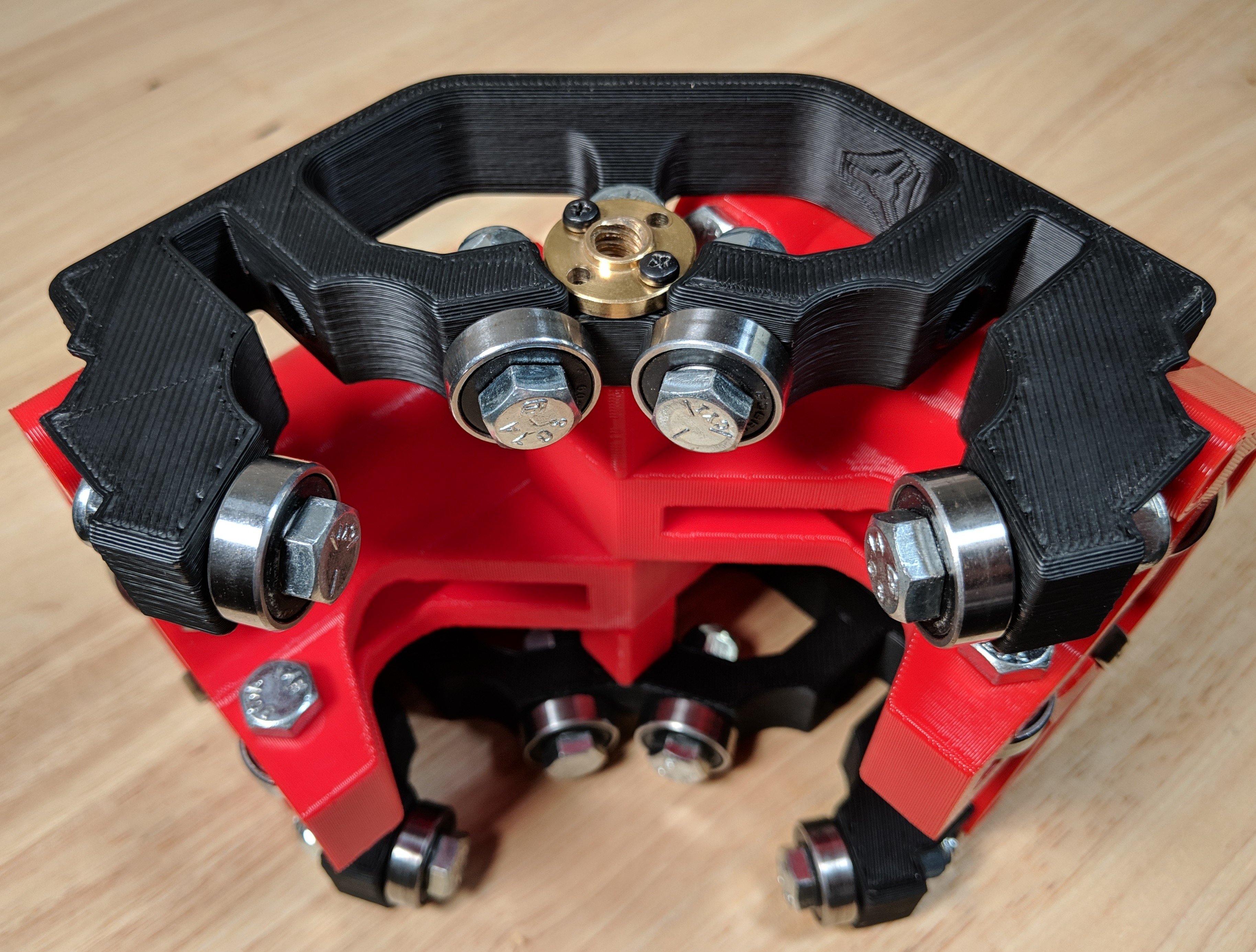
I now have the CNC assembled to check for fit and to work out where to run the cables.

Mistake 1

I should have thought about cable runs before now. It’s not as easy as I would like. Because I made the build fit the 900mm x 600mm base, I have nowhere to run cables easily. I am now printing chain guides that will run underneath the X axis and Y axis as opposed to outside the frame.

Mistake 2

The stepper motor cables come with Dupont connectors. No idea what they were until yesterday and then when I tried to get the stepper motors to connect to the SKR V1.3 board I discovered that the board using something called JST-HS connectors but they don’t fit Dupont connectors. Spin forward 24 hours and I now have an Amazon delivery with a crimper, dupont connectors and JST connectors.

Mistake 3

Don’t cut off your Dupont connectors from your stepper motor. The cables for the stepper motor are going to have to be extended anyway and will need a connector.

Mistake 4

Don’t assume that just because you can wire Cat-6 in your sleep, that wiring Dupont or JST connectors is easy. Assume you will spend four hours f’ing and blinding as you try and work out which jaw you use and how even a 0.1mm variation in things means you start again. Who invented this nonsense? Why do I need to have the patience of a saint, the nimbleness of a house elf and the dexterity of a eight legged octopus to wire a simple connector up. And why do they only put 400 metal prongs in the packet? I’ve wasted 280 of them on my first plug. At the rate I’m going, I’ll need to put an order in for a years supply to get four cables done. My fingers are shredded, the cats run away and the children are hiding in the cellar from me. How could I have been so arrogant to think I could wire a JST plug, next time I’ll stick to something simple, like solving world hunger or DIY brain surgery.

Mistake 5

Finally wired up a single four pin JST plug to discover I have wrapped every cable in the house, plus all the neighbours cables two doors up and down into the same cable ball. I seem to have a nine dimensional mess of cables that now needs to be unravelled. I have a terrible fear that I may need to cut the JST plug off and do it again. The kids have emerged from the cellar but have now gone back down again as they heard me calling on a major deity to give me strength. All three cats are sitting on the roof of the house out of harms way, the dog has taken to pretending to be dead to get away from me.

Mistake 6

Wired the JST plug up, then discovered that the wiring diagram is upside down. So black should be at the other end! I shout at the monitor and expect it to answer back. Am down to my last 10 plugs out of the 400 hundred that came earlier, still don’t have a single JST plug on. Kids have worked out how to open the outside cellar door and are trying to get themselves adopted by passing strangers, all three cats and dogs have gone feral and are living together in a commune in the woods outside, t’other half is ringing solicitor asking about divorce proceedings, but I have now wired a single JST plug. My fingers may be bleeding, I may have used every tool in the garage but it’s now working.

Only four more stepper motors to go…

Next time I buy the wiring harness from somebody.

Rob

12 Likes