Your first jobs are probably just cutting out pieces. If you just cut into your spoil board by 2mm, you don’t care about a 1.5mm error.
If you do really care, you can surface the spoil board, which can probably done in one or two passes since you are so close.
If you aren’t interested in that, or your gantry is not consistent. You can use mesh leveling, but it doesn’t make much sense to do the whole bed. Instead, mesh just the workpiece. Don’t use a bltouch, they are too fragile. Instead, hook up a spatula to the endstop signal and ground your bit. Then subtract the thickness of the spatula. Ryan sells touchplates that work like little spatulas.
Thanks, I’ll look at the spatula’s. Problem is everything takes for ever to come from the US to the UK unless you pay for expediated delivery and for that it’s not worth it.
I have now just completed the correct wiring harness for five stepper motors and four end stops with the correct JTAG’s and DuPont connectors. It’s taken 55m of cables for all of it and my fingertips are bleeding from little nicks from crimping the tags and then bending them off to remove them. But this now means I no longer need the JTAG plugboard that was used to check the wires. I can now run all the cables easily and safely around and through the CNC backto the control board with spare length in case I want to reposition the control board in the future.
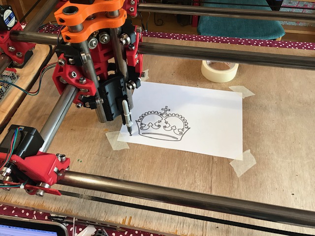
I did try to print the crown but the whiteboard marker needs to be properly mounted. Masking tape isn’t good enough So the Ender 3 is now printing a couple of decent pen holders for me to try.
So next steps are
Mounting the end stops
Running cables through sleeving
Remounting the ‘control board’. The control board is a plank of wood with an Emergency Stop on, a 24V 150W PSU, a Raspberry Pi 4, an SKR V1.3 and a RepRapFull Discount display. Remounting it involves a longer plank
Getting Octoprint to work with it all.
Working out how to raise one corner by 1mm to level everything out. I reckon that’s all thats needed and 1mm is enough for me. I need a small, precision hydraulic jack, or more likely a couple of nuts and bolts so I can turn them a turn or so to raise one corner.
Getting the Raspberry PI to work off a 24v/5v buck. The Pi is very sensitive to low power.
Doing some calibration prints.
Doing some more calibration prints.
Working out if the belts are tight enough. Difficult to know if this is OK or not.
Control panel now redone. Basically a longer plank of wood so everything fits on.
First crown drawn. Looks pretty good to me, but a Sharpie is quite thick. I have some very thin pens and will try those later. Also need to find some calibration pictures to test parallel lines etc. I supposed I could use this as an expensive Etch-A-Sketch ™.
Still need to do the end stops, but thats enough for today.
A spatula, or anything necessarily purchased, isn’t required. Anything flat conductive and of consistent thickness will work.
A piece of PCB with a wire soldered on works great, or a piece of copper, brass, or aluminum sheet or plate would be fine too. Doesn’t need to be anything fancy.
Heck, get some aluminium foil, pinch up one end, and use a wire with a clip on one end to connect it to the endstop. Depending on how cheap you are on your cooking supplies, you might not even have to account for the thickness…
Alternately, dig an empty can out of the recycling bin, clean it up, cut it up, and use it as a touch plate. You’ll probably want to break out your calipers and get its thickness. Especially if you’ve been staving off COVID-19 with Guinness…
There’s an awful lot of hi tech tomfoolery here. Our bandwidth to the house is an average 890Mb download and 930Mb upload. Yep, thats Megabits. £30/month all in, no limits apart from I’m not allowed to touch the Genexis router / fibre modem and ‘play’ with it or throw it away and put a proper bit of Cisco kit in. The provider doesn’t like that. I also can’t use port 22 as they need it to ssh to the router for service checks.
Apart from that, anything goes. We have a VMWare ESXI server, email, AWS links, NextCloud. I provide storage backup to a number of the houses in the village as the bandwidth is so great, who cares. The local shop is all wired up for VOIP, indeed many of us don’t waste our time with BT at all. I’m just about to put a local mobile cell in as the mobile provision here isn’t fantastic and our house is a blackspot, 50 meters each way is OK, just us
I will make the CNC machine and 3d printer available for people to use. I can see the local farmers being first in the queue.
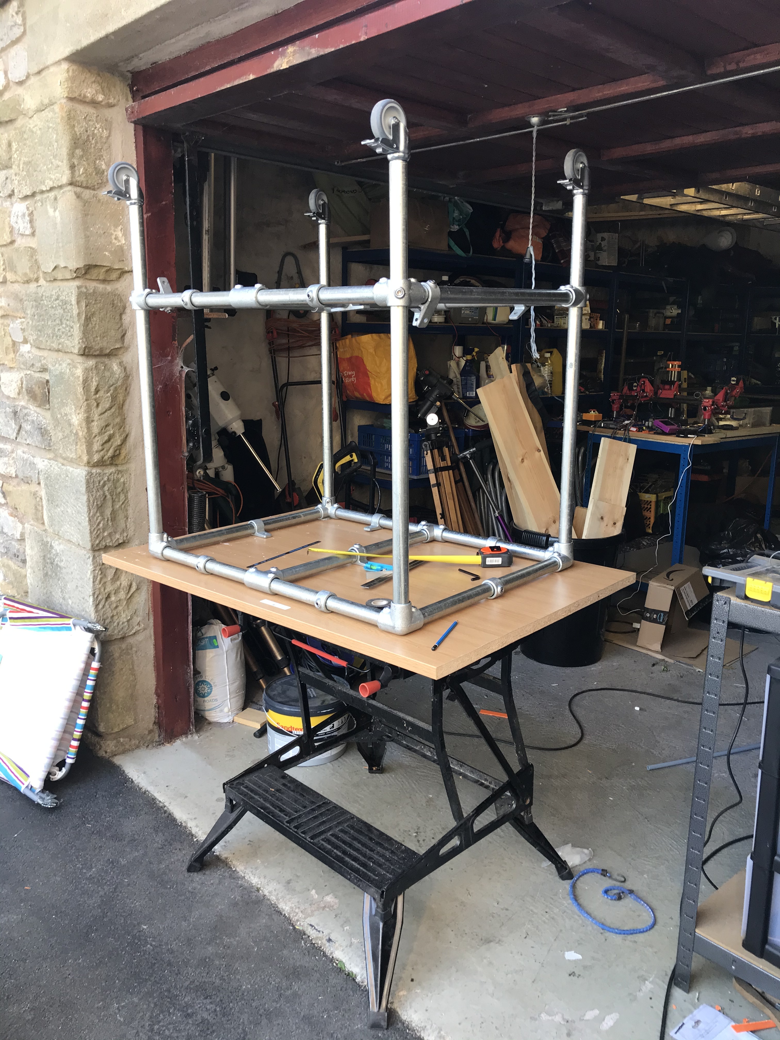
Still working on finishing MPCNC. I had to move it to the garage as the CFO wanted the dining table back.
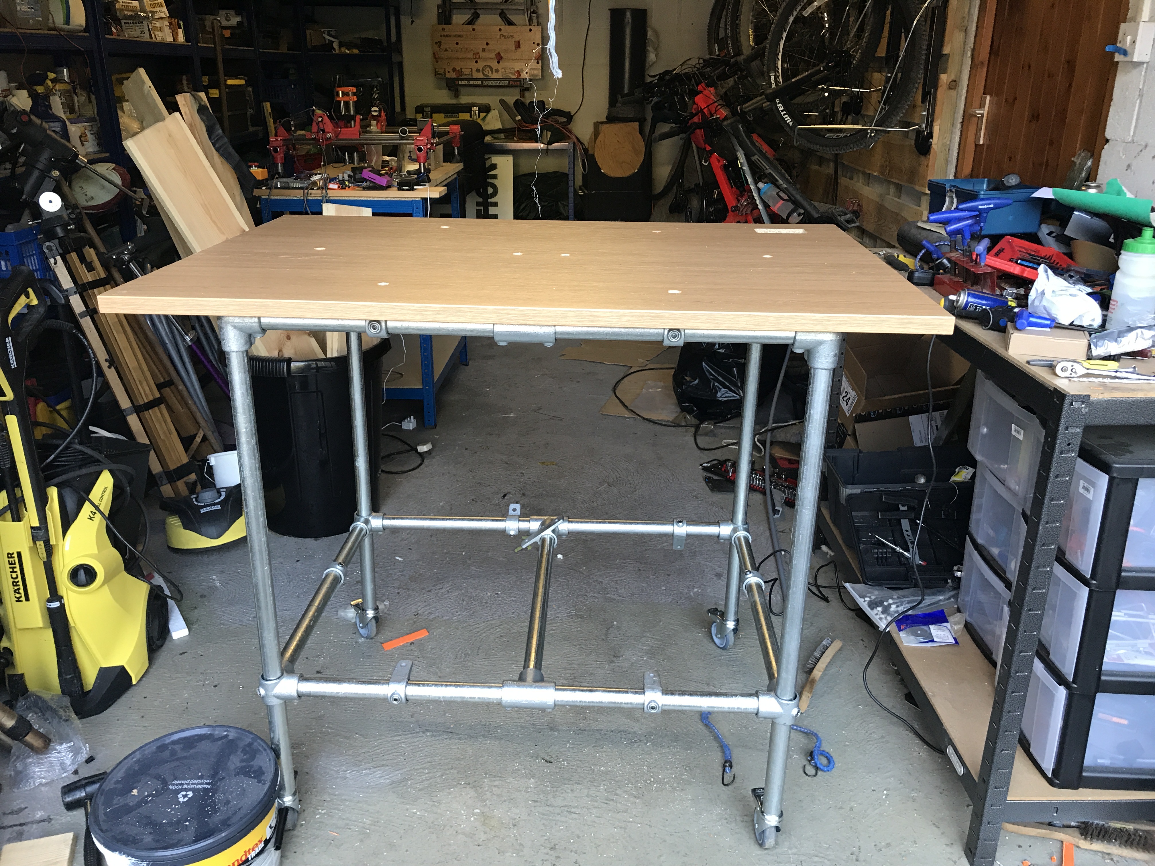
It turns out the ‘heavy duty’ garage stand that I got from Amazon was made of wet tissue paper and was useless. I also wanted to be able to move the CNC around so invested in a series of 33mm pipes, clamps and castors. This is a seriously strong table that weighs close to 40kg (100 lbs) and will withstand a small bomb. I may have over specified the tubing…
The top is a desktop I had lying around. I cut it down from 1.8m to 1.2m. The remainder will become a spoil board or at least my first attempt at one.
Router on order but delivery late. Polystyrene blocks on order for testing cuts. Will test out Eastlcam under VMWARE Fusion today. Hopefully it will be simple enough for an idiot such as me.
I still need to put the dual end stops on. However the official docs and none of the posts indicate which end they go. I am assuming the equivalent of (0,0) but after spending a good hour looking, nobody seems to state this and just assumes you know. A clarification and confirmation would be most helpful.
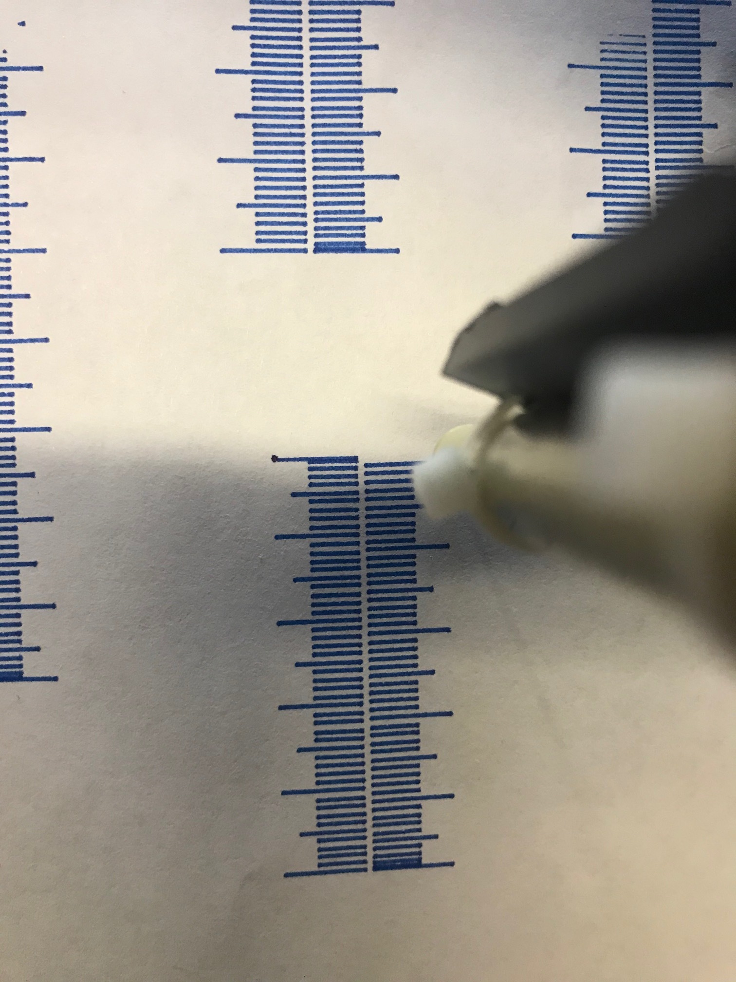
The picture shows a 100mm square though it prints as 98.7mm in the X axis and 100.2mm in the Y axis. I find it difficult to measure down to 0.2mm though.
What is noticeable in the X axis:
It’s the wrong size
The X axis ruler is printed in two sections, the bottom first and then the top section of the ruler is printed second.
On the top section of the X ruler at the right hand end, there are thick lines where multiple lines are printed together.
The top part of the X axis ruler marker lines are well out of sync with the bottom lines, This can be seen in the red squares. Indeed the left hand red box shows the end of the line being out by approx 1.75mm.
This set of errors is consistent (ish) with the top X Axis ruler.
The X Axis markers are not consistent at all and are slight varied.
None of these errors are noticeable in the Y Axis.
So the X axis is rubbish, need to find out why,
My 1st working assumption is that this is due to the belt tension being wrong and that this is shown as inconsistent marker lines as the X Axis increases. It then shows up when the X Axis direction is reversed (thick lines at the end as there is too much slack and it simply doesn’t change direction fast enough. This eventually shows up as the top part of the ruler is actually 1.75mm short. Rubbish
Before I start tweaking things, does my analysis make sense at all? Or is this due to something else like bearings or phases of the moon, or voodoo?
It looks like backlash. The first few mms of travel are accounting for the backlash. If the set screw is moving along the flat of the motor shaft, that would do it.
Will now look at the bolts holding things down, perhaps the deceleration of the x axis is making things flex as the weight of the Z mount needs to be stopped.
Can you slow it down? Just to see if that matters?
Is there anything you can see with your hands and eyes that might be causing this to be loose? It doesn’t look dynamic to me. I imagine if you just engaged the motors and applied a small force to the rollers, it would move a little in one direction (X) and not the other (Y). So it should be possible to see what is moving.
Have been doing that already to see if there is anything looser or binding. It doesn;t feel any different in any way.
Took the belts off, retightened the grub screws on the pulley wheel. Reattached the belts. Pretty damm tight
Tightened the corner pieces so they are all snug.
Dropped the speed down to 1/4 and still the same result. When the x axis reverses it seems to lose ‘grip’. Always two mm, tried this on different parts of the bed, same result. I’d swear blind that the pulleys are tight
The only thing I can think of now, is the X axis carriers, so I will check those tomorrow. Wonder if a bearing is slightly askew and when you reverse it, it snags (or something). Not sure about that as I have tried different ruler lengths.
I’ll also try squares in different parts of the bed in different sizes.
 So the Ender 3 is now printing a couple of decent pen holders for me to try.