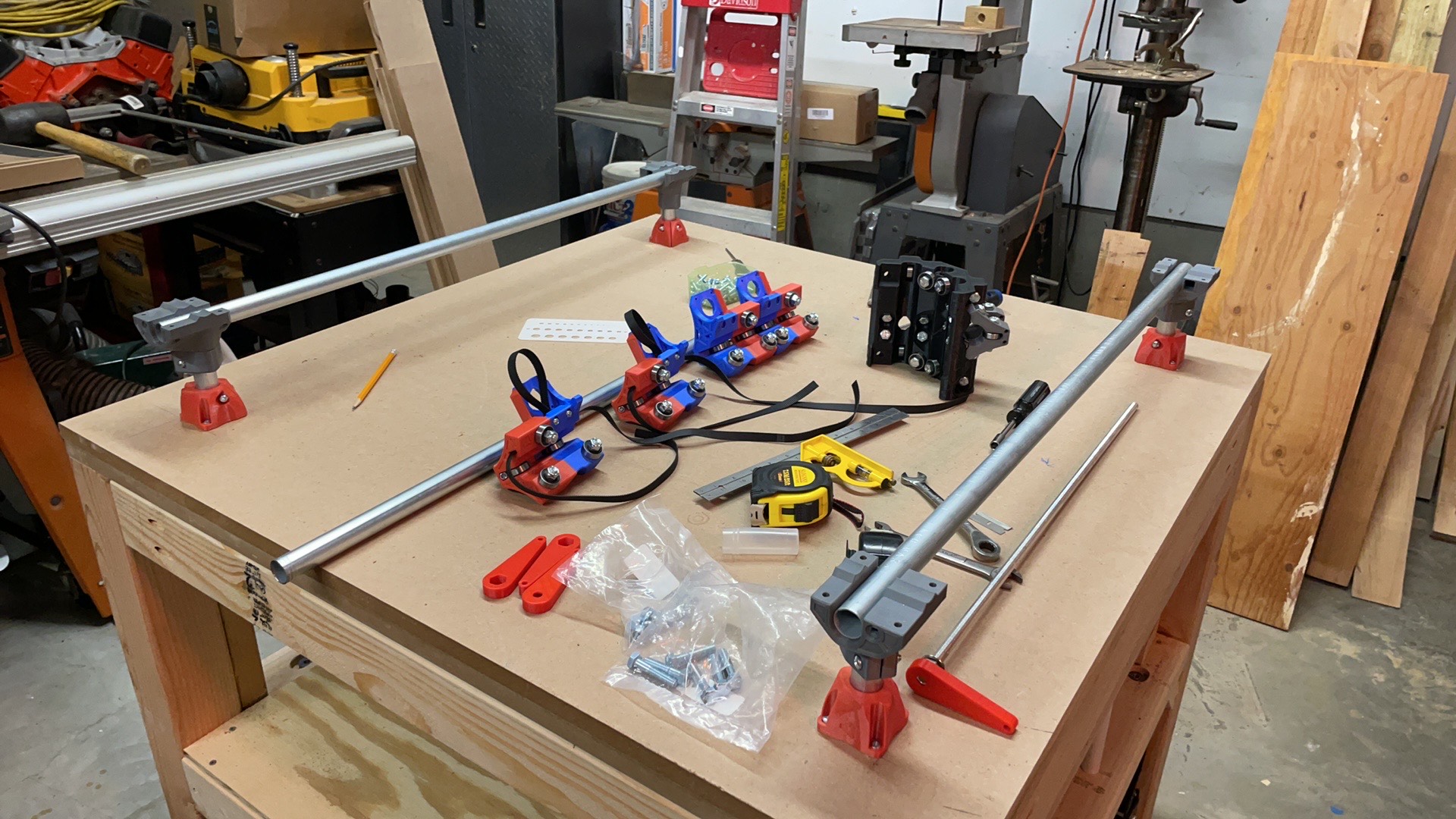
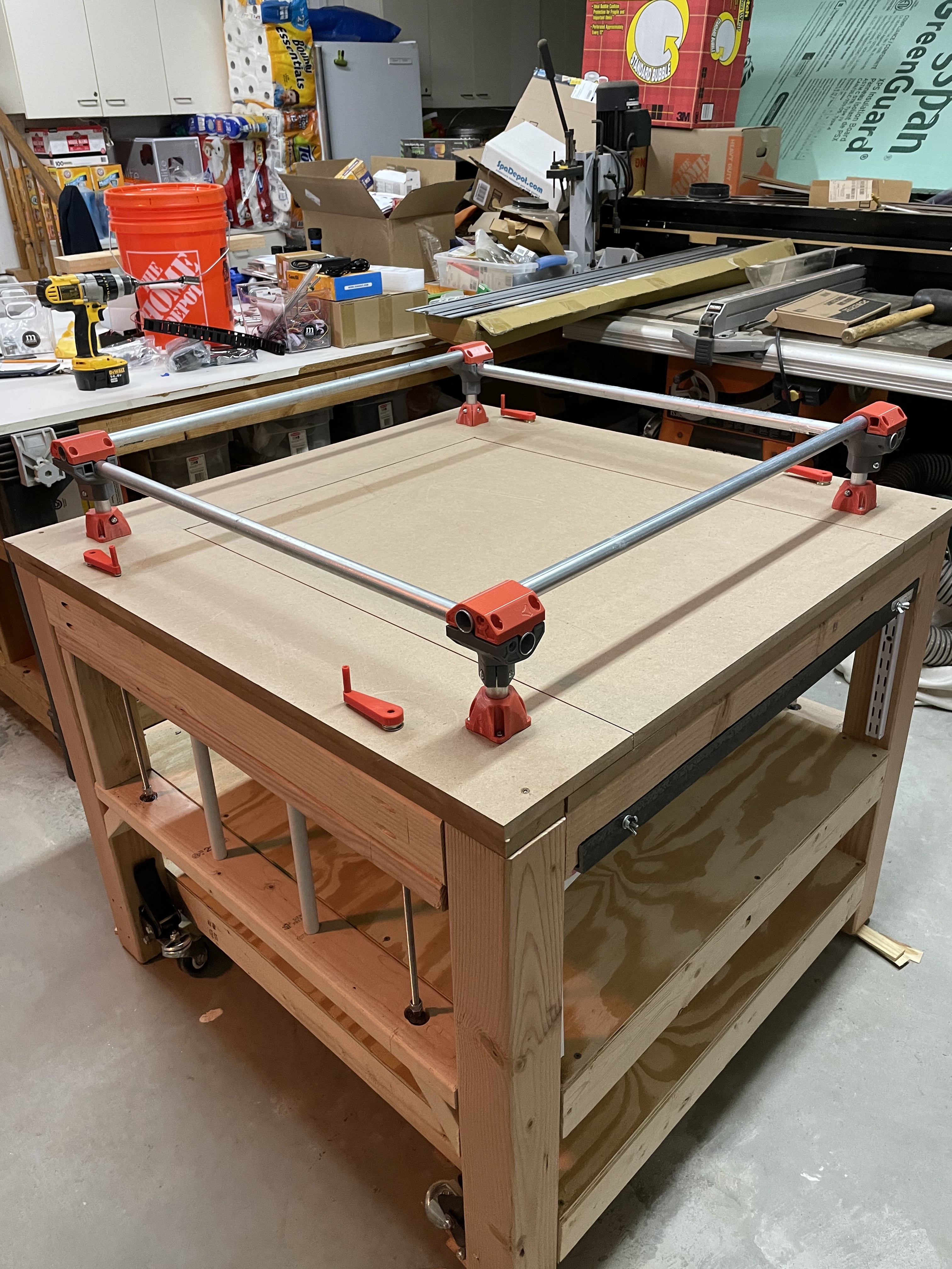
Today was supposed to be the day - I spent a couple of hours every day this week squaring up the trucks, installing the belts and prepping the wiring.
My reading up in the forums definitely informed me of the gotchas… but I am here to report, I FOUND A NEW ONE! (well, 2 actually)…
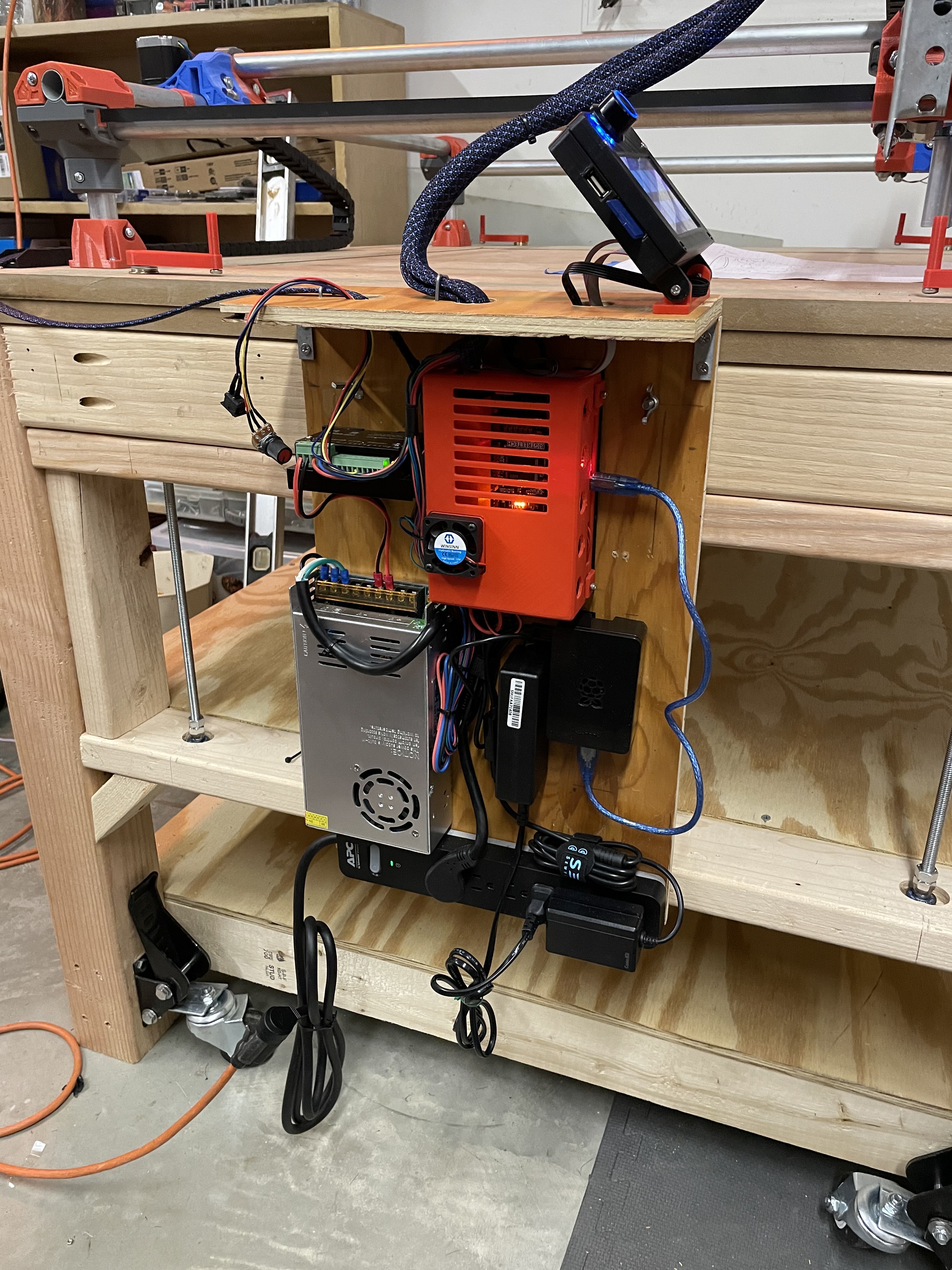
Since I had a metric meltdown and ordered insufficient belt, I had to wait on a belt order from V1. I had found a printable case for the TFT. While I was waiting for the belt, I got all of my electronics prepped. Bent the sensor pin, pulled the jumpers on the SKR board, downloaded the firmware, and installed the TFT in its case (<- this is noteworthy.)
I put the serial wiring on first (even though my ultimate goal was dual end stop), hooked up the SKR Board and the TFT. I suffered through the “Printer not found” error for hours… I noticed forum comments about baud rate, but all I saw was the home screen offering me Marlin or Big Tree… pushing down on the knob briefly flashed a screen with menu options, but they would not stay. I found the config.ini file and found the baud rate setting in there, modified it and tried again. No luck.
Noting that some had gotten bad boards (or damaged them during setup/config), I was beginning to think I had a bad board. I removed it from the case, and gave it a close inspection. Nothing stood out… So I went back through the entire firmware process on both boards.
I have a repurposed Dell laptop with Ubuntu linux and downloaded Repetier Host. So I spent most of the better part of 3 hours trying to get something to work - no printer found, no menu to reset baud rate and zero connectivity with the laptop. Very frustrating.
more googling, more forum research, looking for anything to break the log jam…
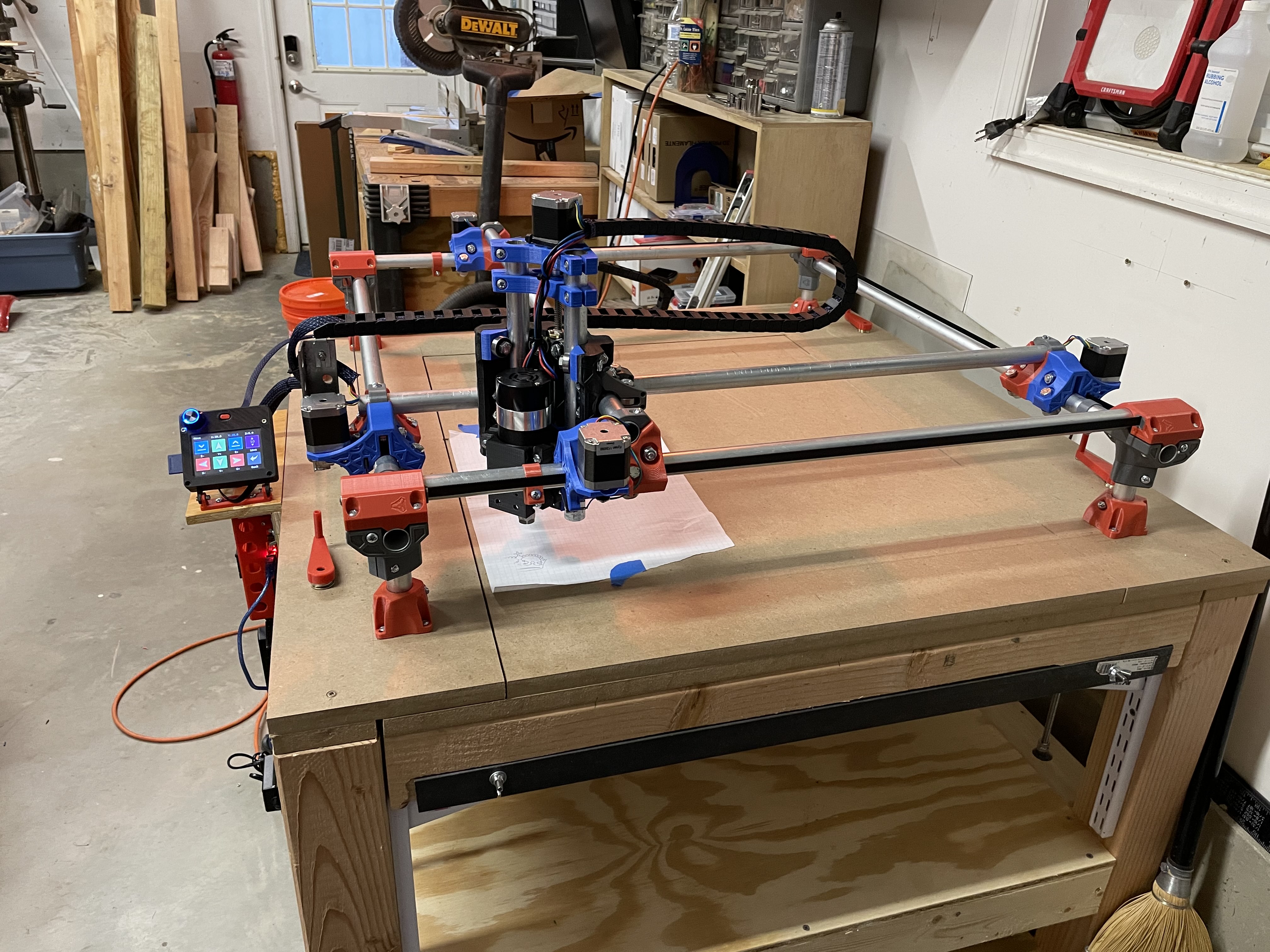
I decided to try out my windows laptop with Repetier Host and it worked the first time! (note to self, apparently linux and DELL have issues with serial ports). I went to manual and tried out each of my axis - Y motors were opposite and Z was backwards. Got it all straightened out and proved that it would move! (YAY). I do have video evidence. 
I decided to power the board and TFT while NOT in the case… I GOT MENU! I found the configuration setting for baud rate and got it connected. The printed case was slightly smaller than the screen and compressing the touch screen! Grrrrrrrr…
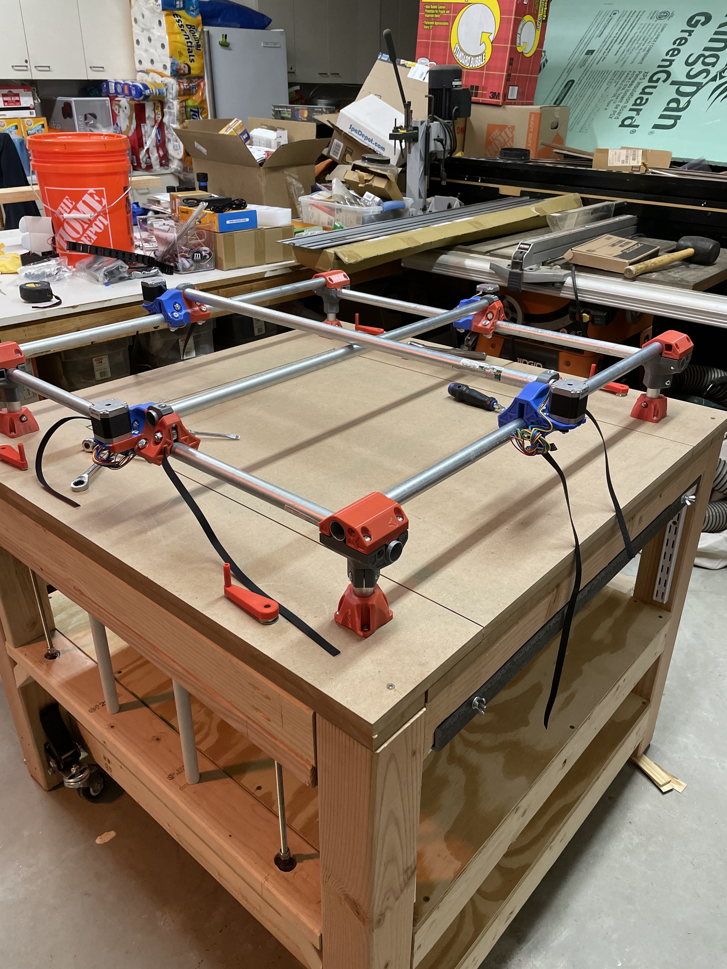
With everything now working, I switched over to Dual End Stop wiring. I got everything all hooked up, soldered the switches, put on the dupont plugs to go with the V1 wiring and did my continuity checks, reflashed the firmware and felt like the day was going to end on a high note.
NOT.
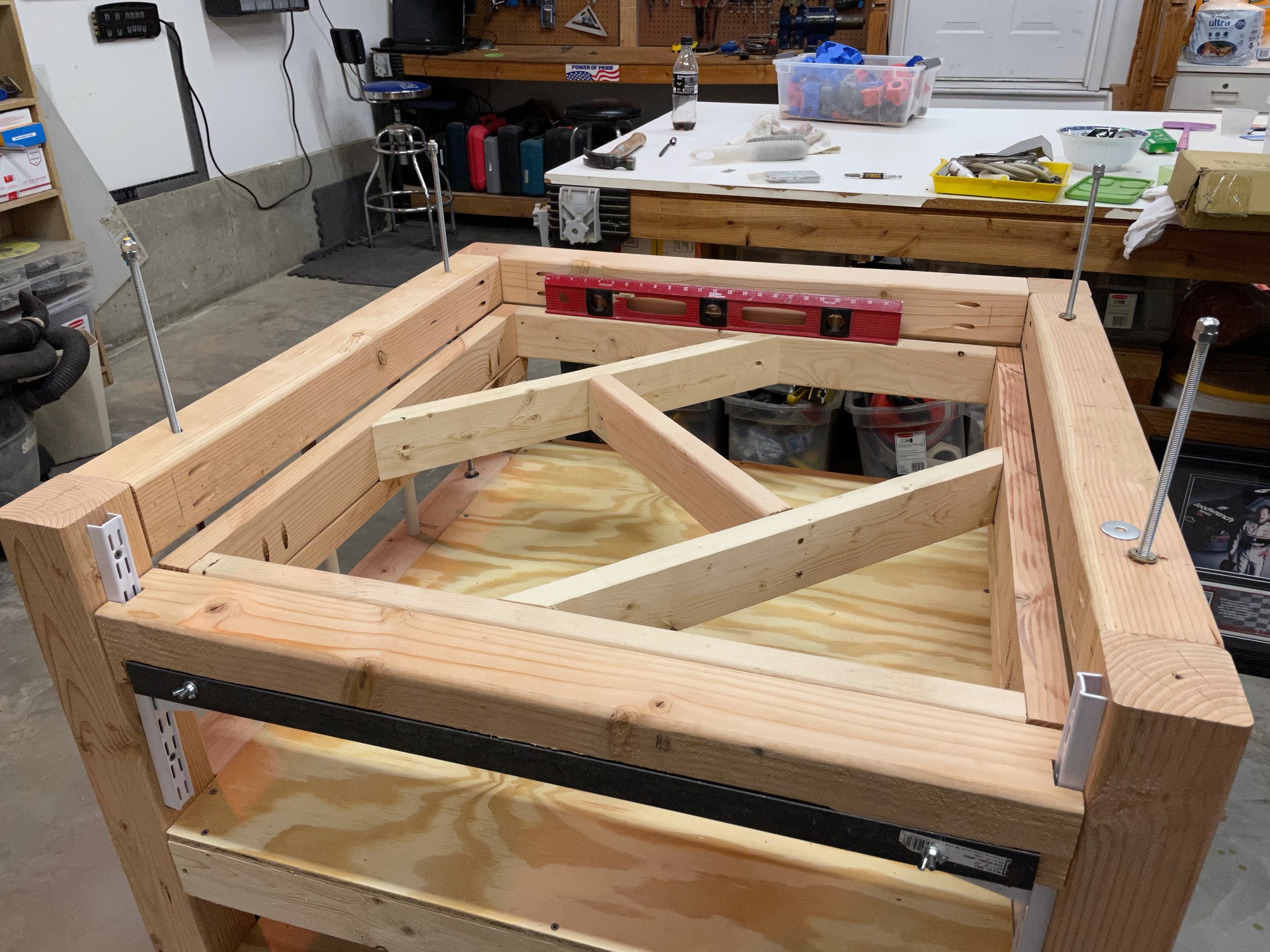
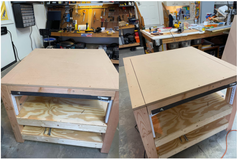
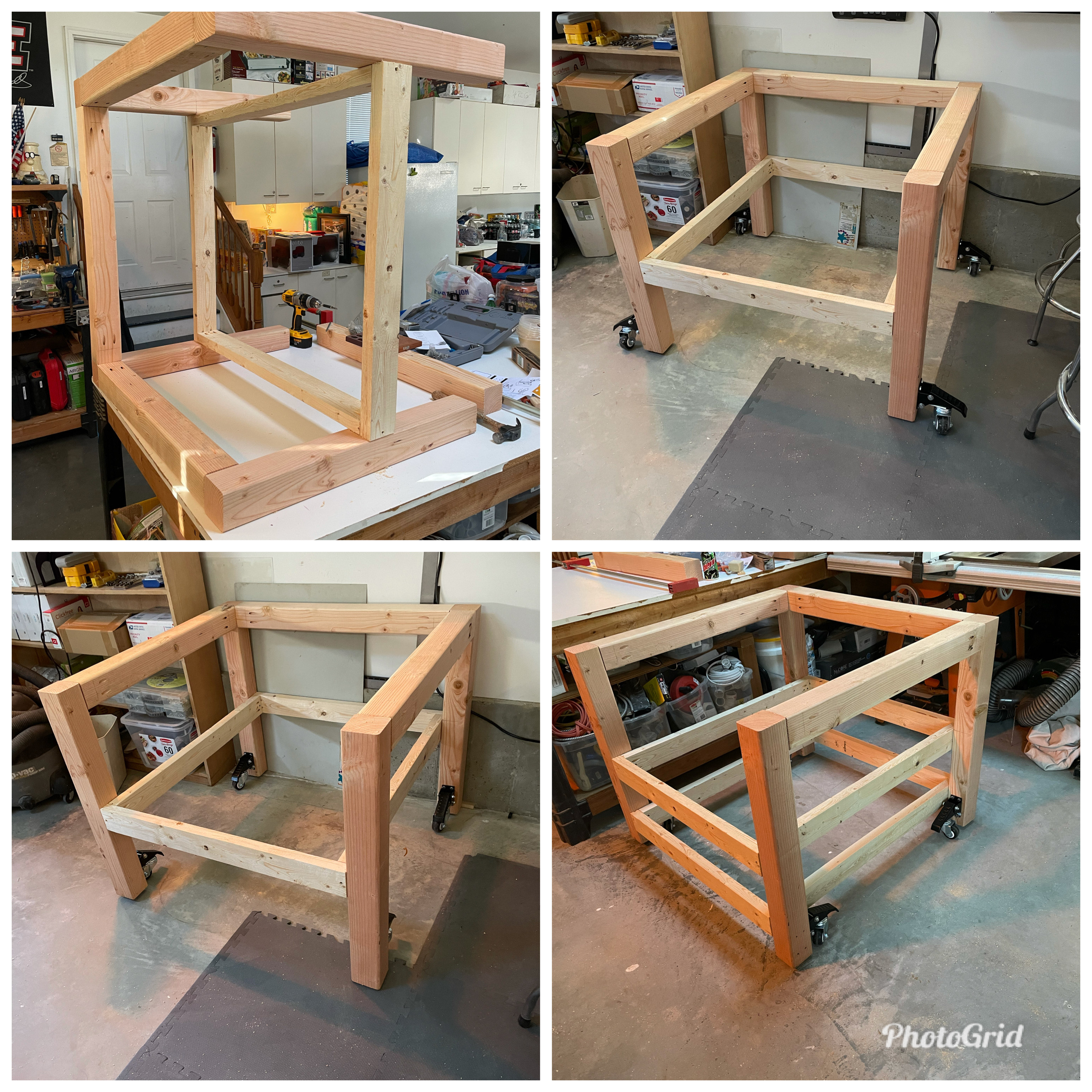
Because of the way I have my table oriented (to have it level) while building it, I somehow have the Y trucks on backwards. When I was playing with the end stop switches I noticed they were opposite of the origin (min 0,0). I mostly work on it from the left side instead of front and aligned them to that.
Back at it tomorrow, where I have to tear part of it down and switch things around.
We are close!
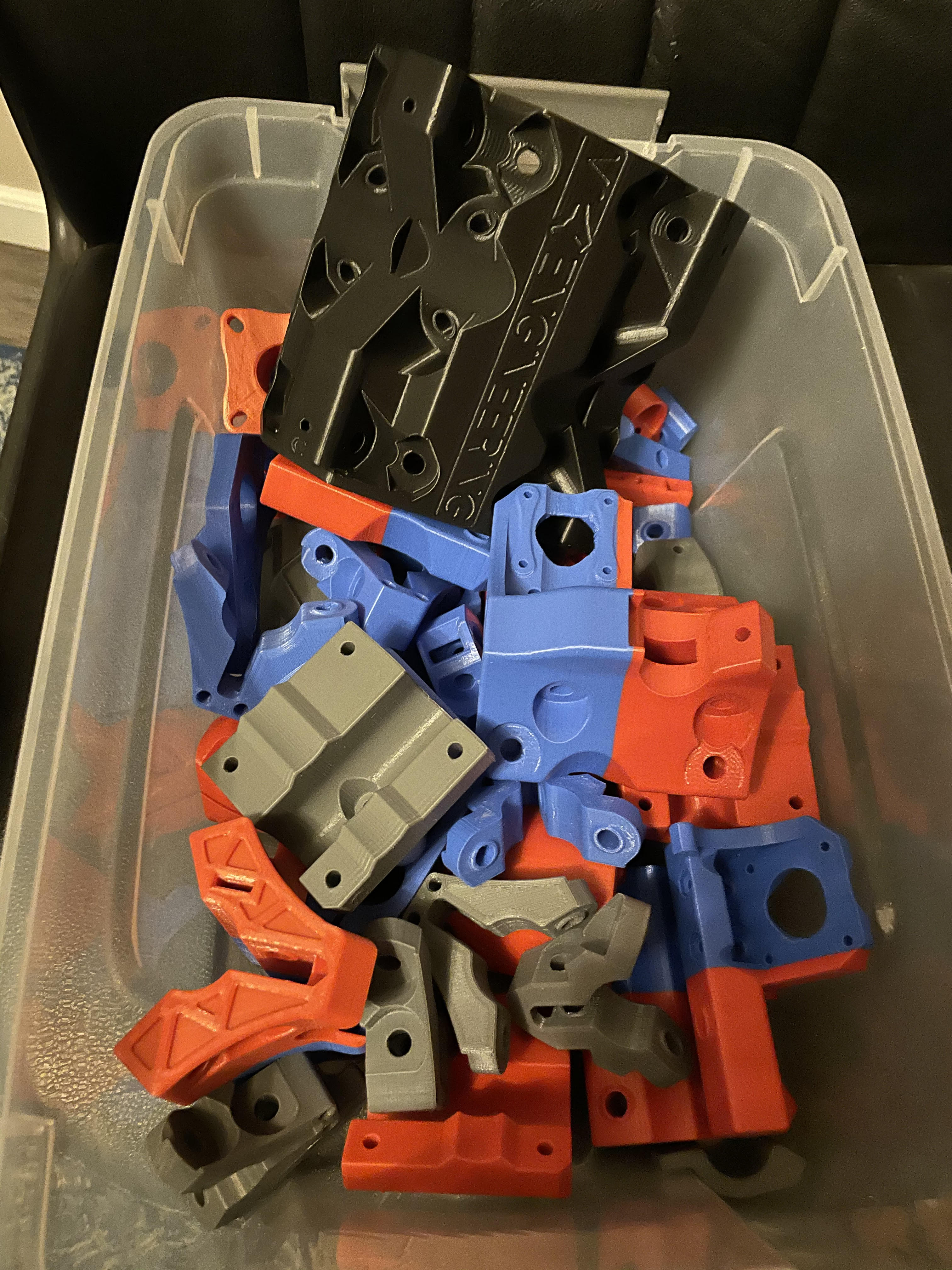
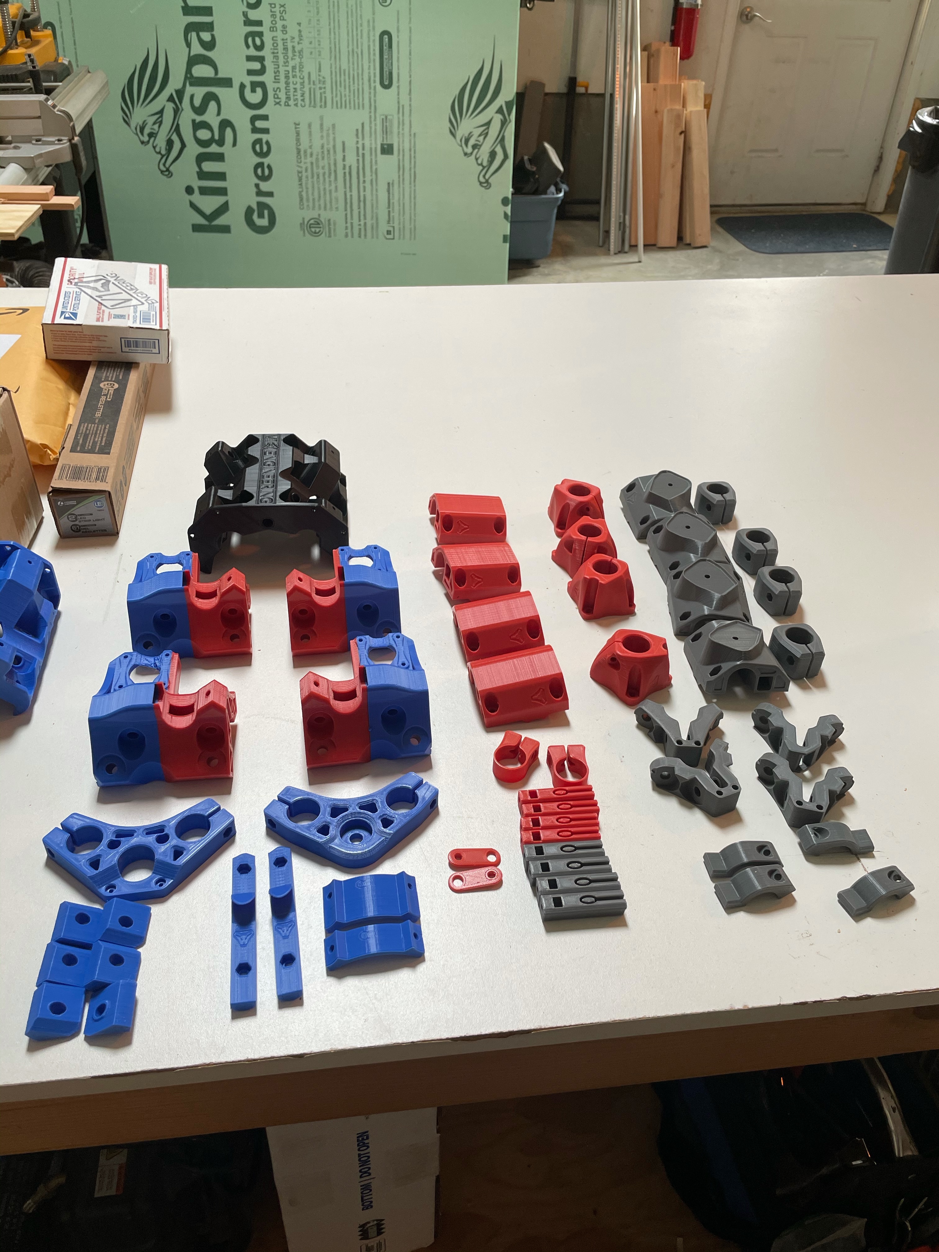
 ). I have all of my supplies in hand.
 can’t wait to see it covered in dust or old g###
 …
…