And so it begins…
Slowly, very slowly!

4 Likes
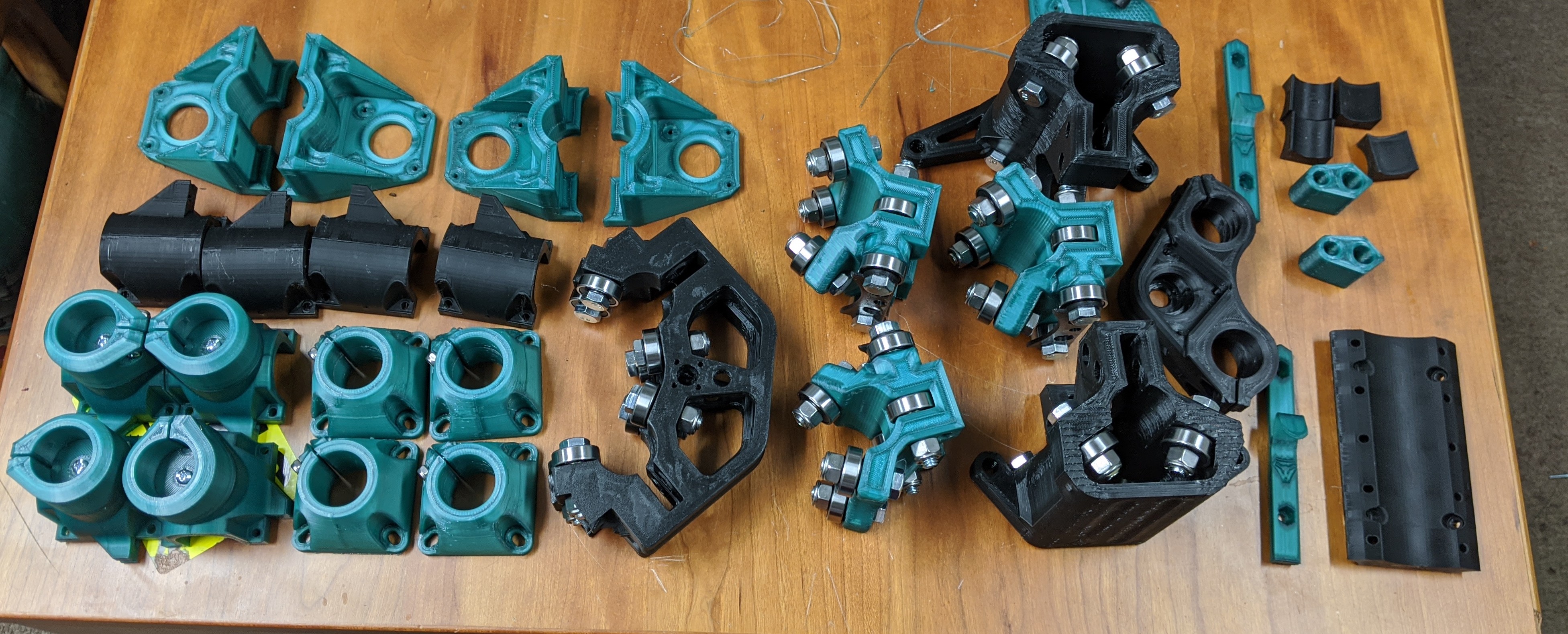
One part down… 300 parts to go 
Welcome to the club. I’m on the last 12 parts for my dad’s MPCNC. About 2 days worth of full time printing to go.
I feel guilty. I haven’t printed anything on my two FDMs in over a week. I really should just start printing the lowrider parts for the heck of it because I know I’ll get to it some day. But I know better than to print parts without conduit in hand.
Keep the posts coming!
1 Like
That and by the time you get around to it, there might be an update.
1 Like
I must admit, I sat on the fence for a while, not knowing what to do, while the Primo started getting teased like a stripper in Vegas.
But in the end, decided Primo be dammed, to go ahead with the build, figuring I can always upgrade later.
Not to mention, it will take a few months for the Primo dust to settle, and some time for me to crank up the Ender again.
End up going with 1" DOM from Jegs, couldn’t beat the price for product or the incredibly low shipping cost.
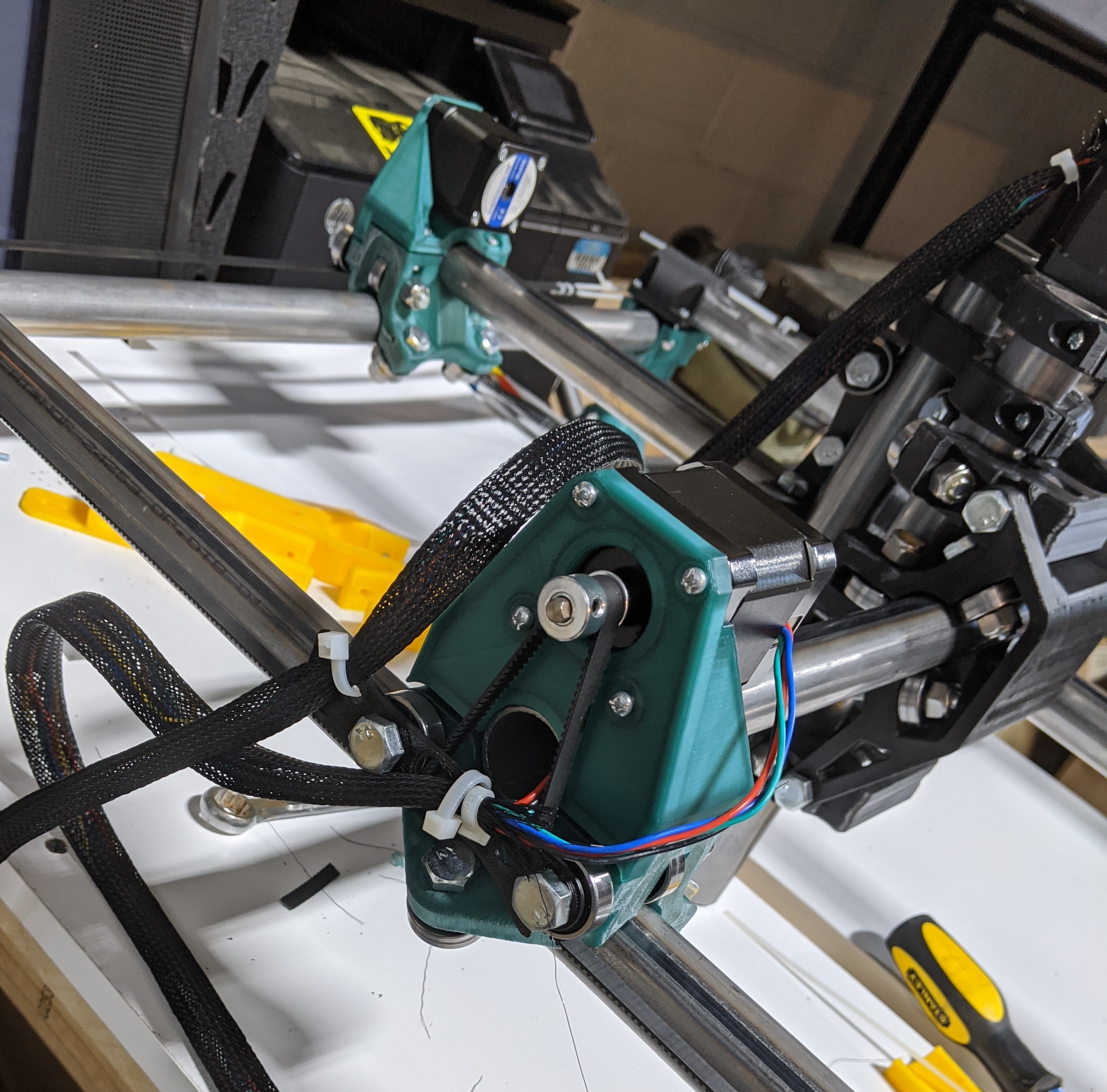
Waxed it up nice…
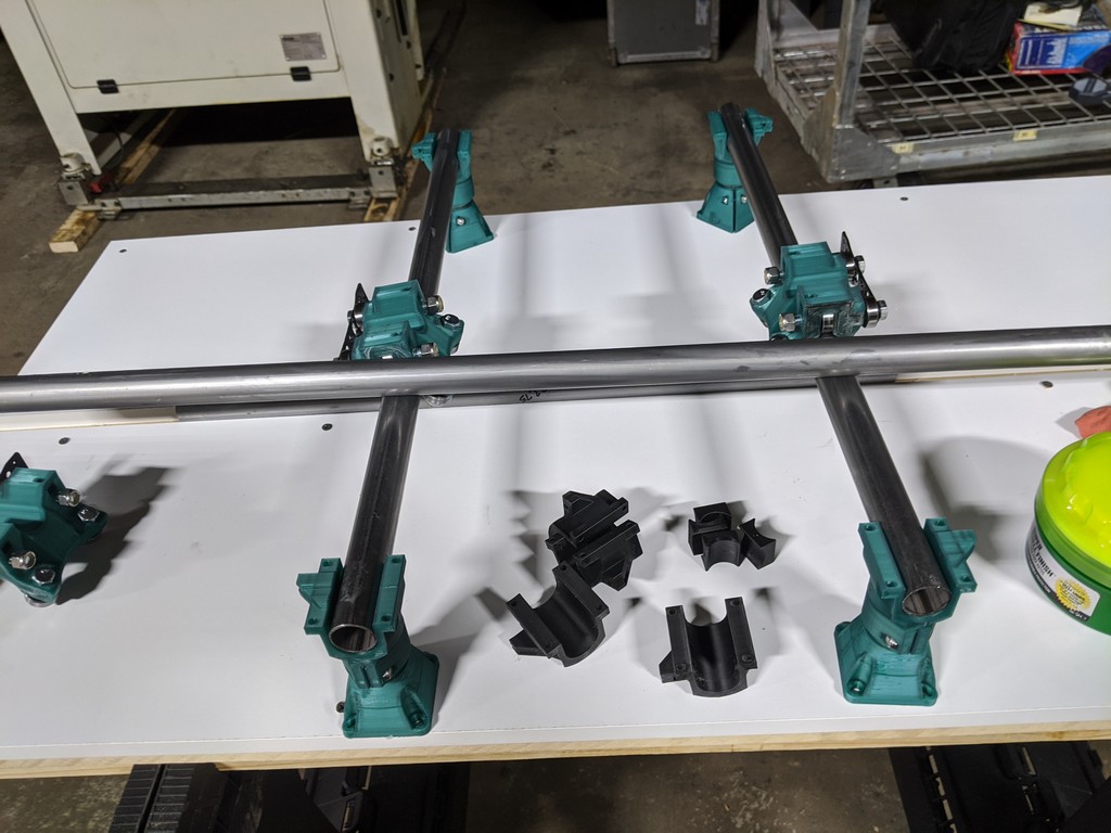
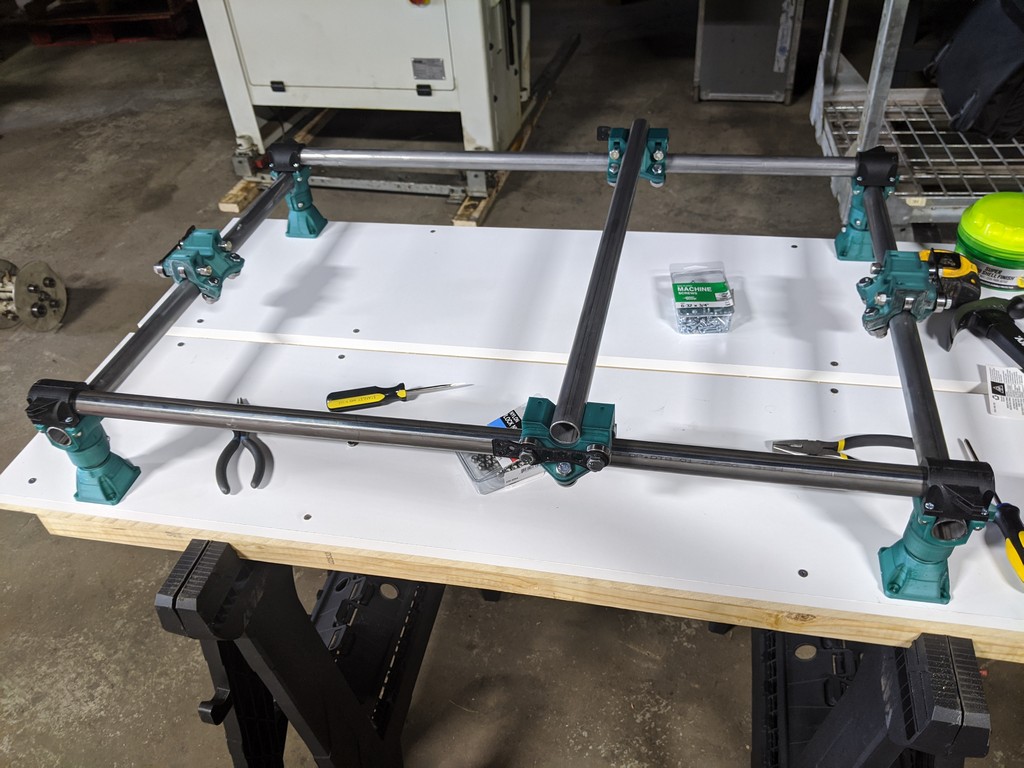
Steppers attached, Legs mic’d to .1 mm, ready to square up & fasten down.
Like some others, neglected to take more photos along the way, but it is what it is.
Table is a simple affair, 3/4 mdf topped by white coated mdf shelving.
Home Depot advertised it as 12" wide. Actually turned out to be 11.8 when delivered, but since I will be cutting out the whole center section for a proper spoil board, not the end of the world.
Goal was a 12 x 24 cutting / spoil board area, nice size to easily replace, and the white finished perimeter I thought would look nice and be easy to clean.
Overall size 23.75 x 34.75
One requirement was big enough to cut out LowRider parts.
But that’s another story for another build…
2 Likes
It looks great. The primo is stull very new, and there is a lot to learn without also looking at any primo bugs. That machine should be a great platform.
It is really hard to stop and take photos, because the next step is right there. You got a few though.
The no Update Update.
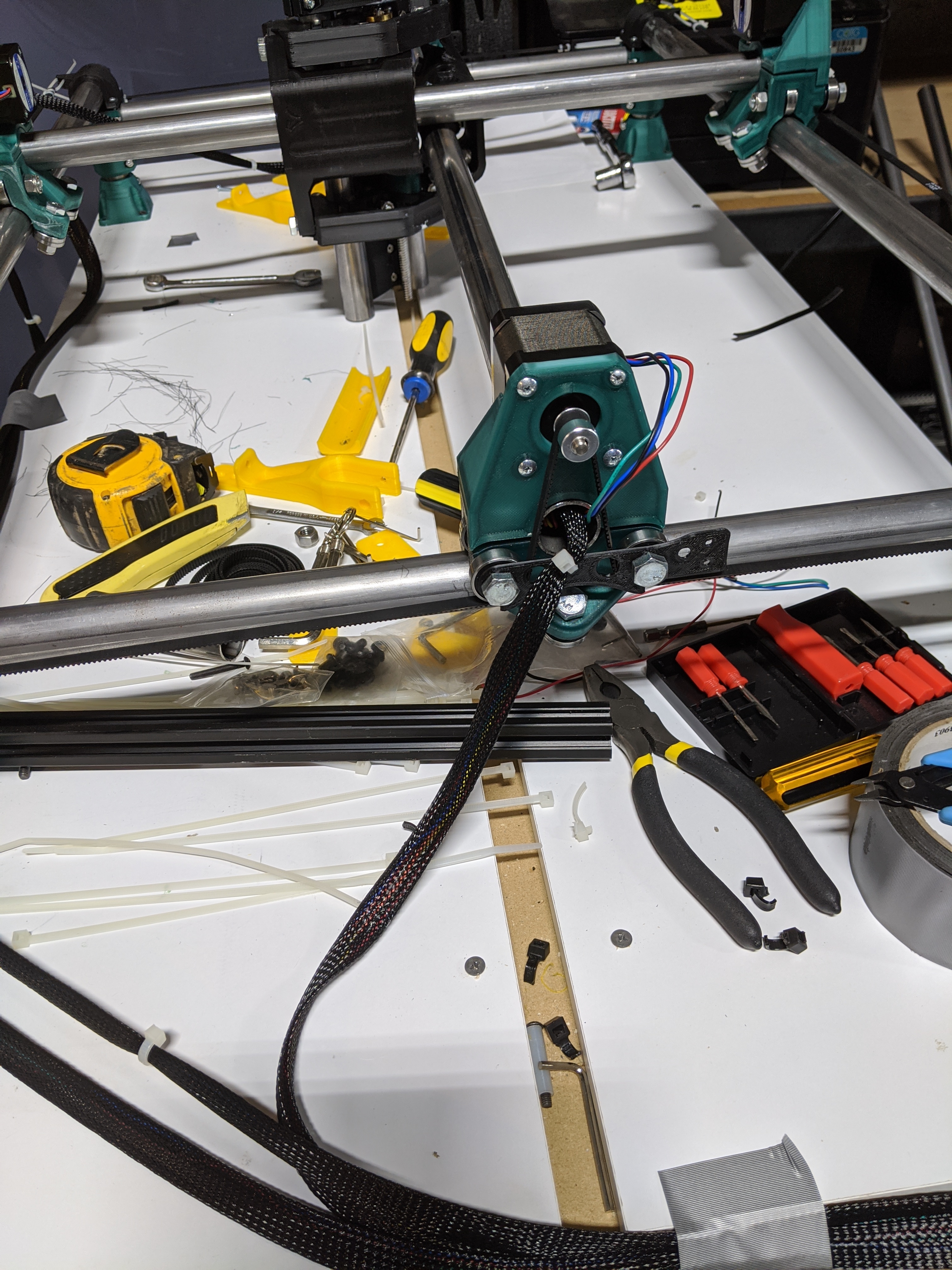
So I’ve been stalled for a month here. Telling myself I have to print pen mounts and cable carriers, and mid-span feet, put the wiring in cable sleeves, when the truth is, I have to cut some wires and hook the damn thing up.
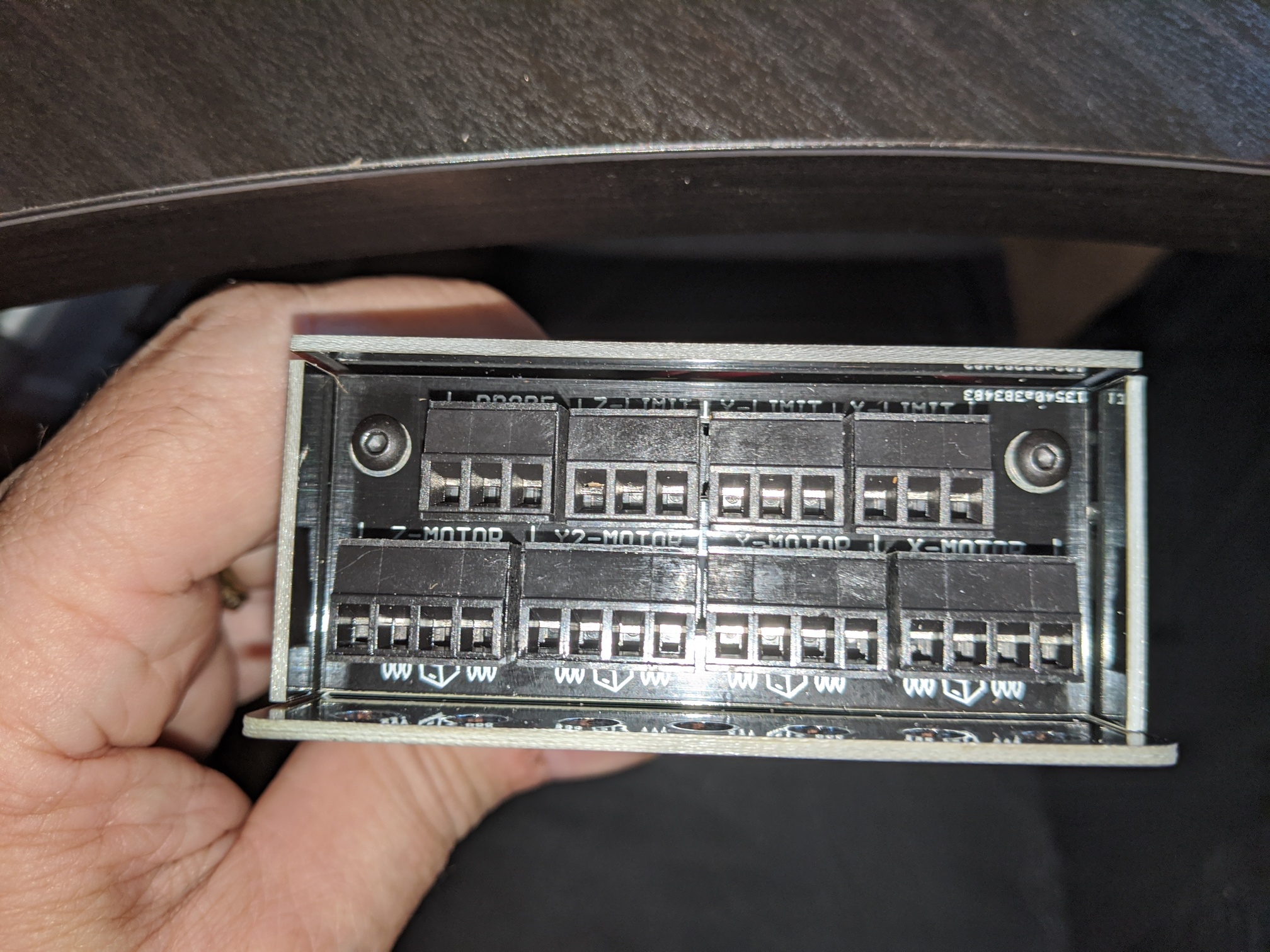
Unlike most of you, I’m mating this beast to an openbuilds controller because I already had it, and now my fear is I’m going to get something wrong in the wiring and blow something up.
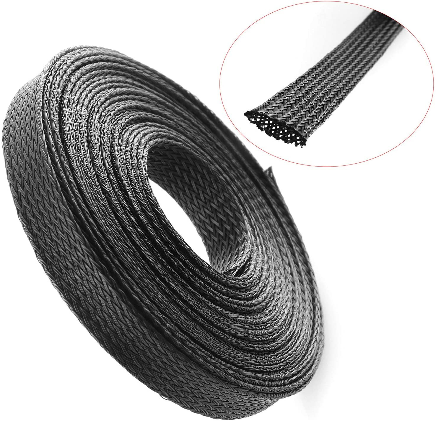
Totally irrational, and I have been making excuses but Monday is the day (if Amazon delivers the braided wire sleeve early enough - I do believe I should pull my wires out of the tubes and put them in this before I go too far).
Anyway, there’s the no update update. I won’t be posting more until there truly is something to report!
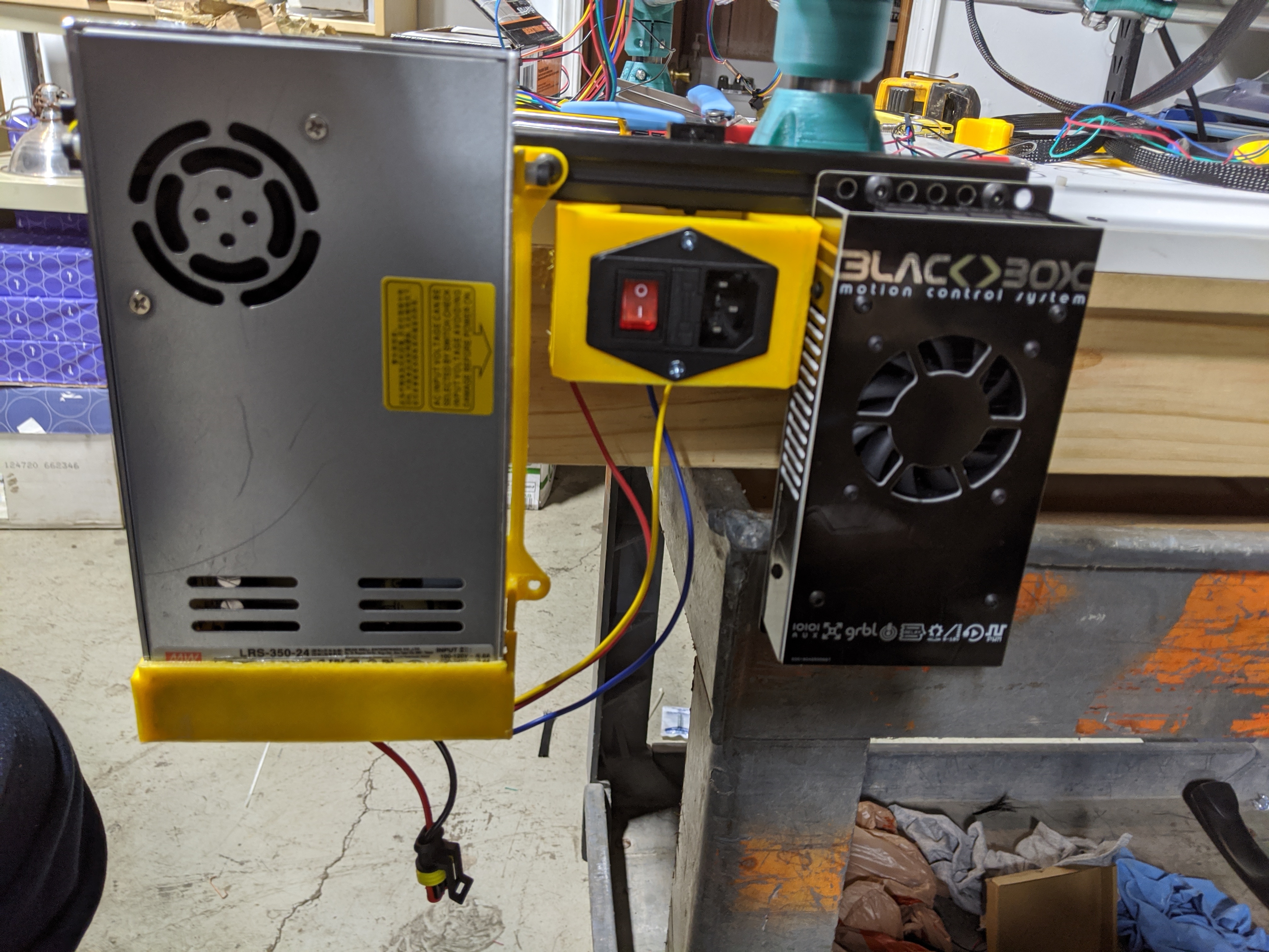
Well some progress. Got the braid covering over the exposed wires - did not run braid thru tubes. Time will tell how big of a mistake that is.
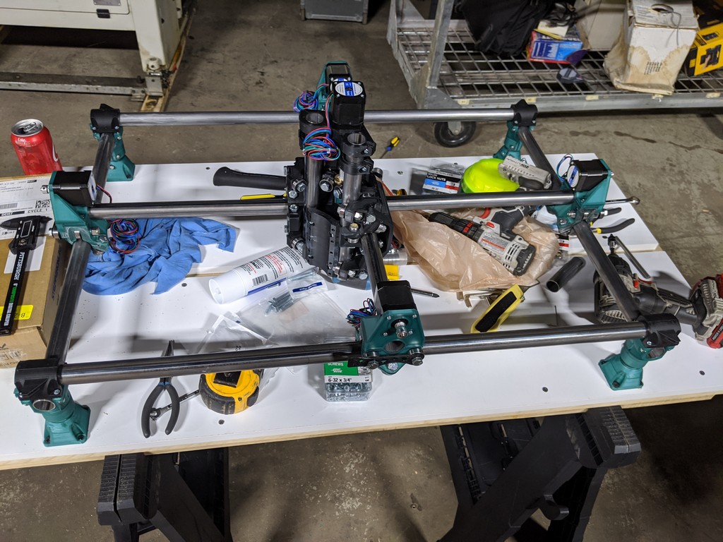
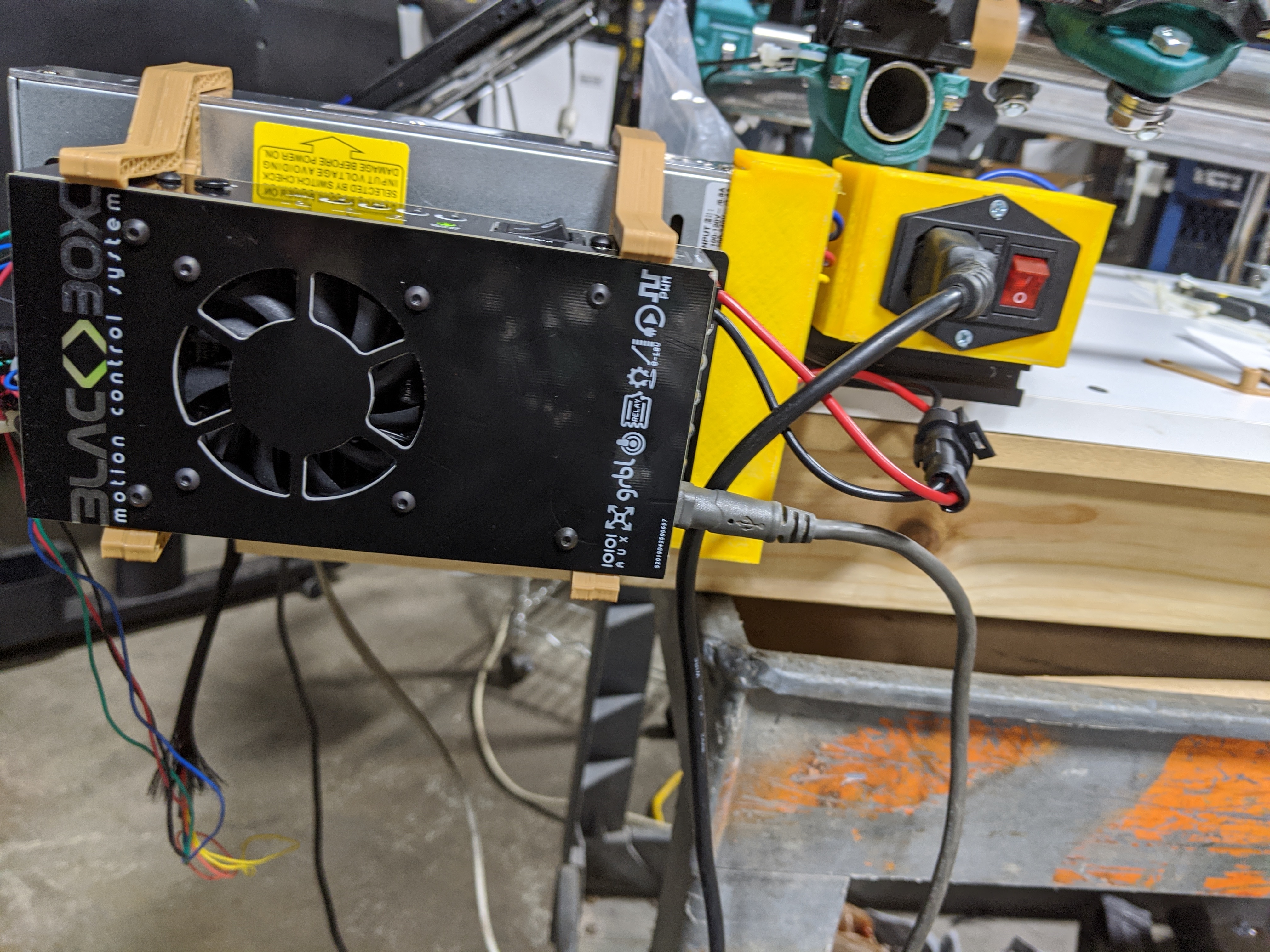
Got my power supply, mains input and open builds control mounted.
Now I just have hook up the connectors and power up?
Oh and print some belt guards - I can see how the wires could flop into the belting.
1 Like
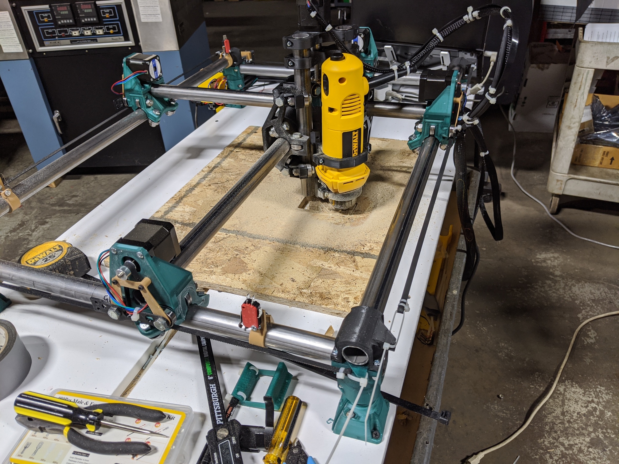
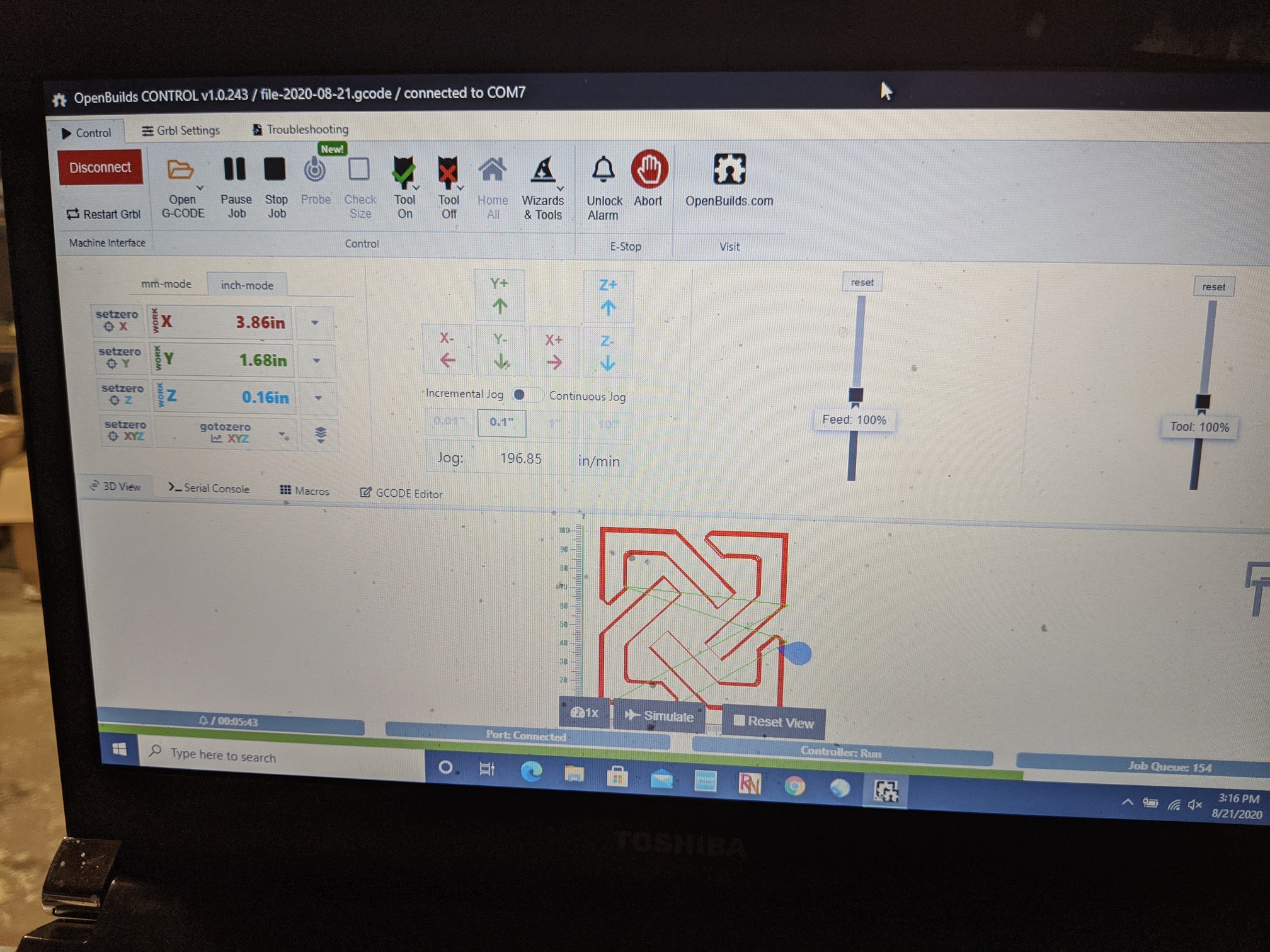
Well finally put power to it and here’s the crown

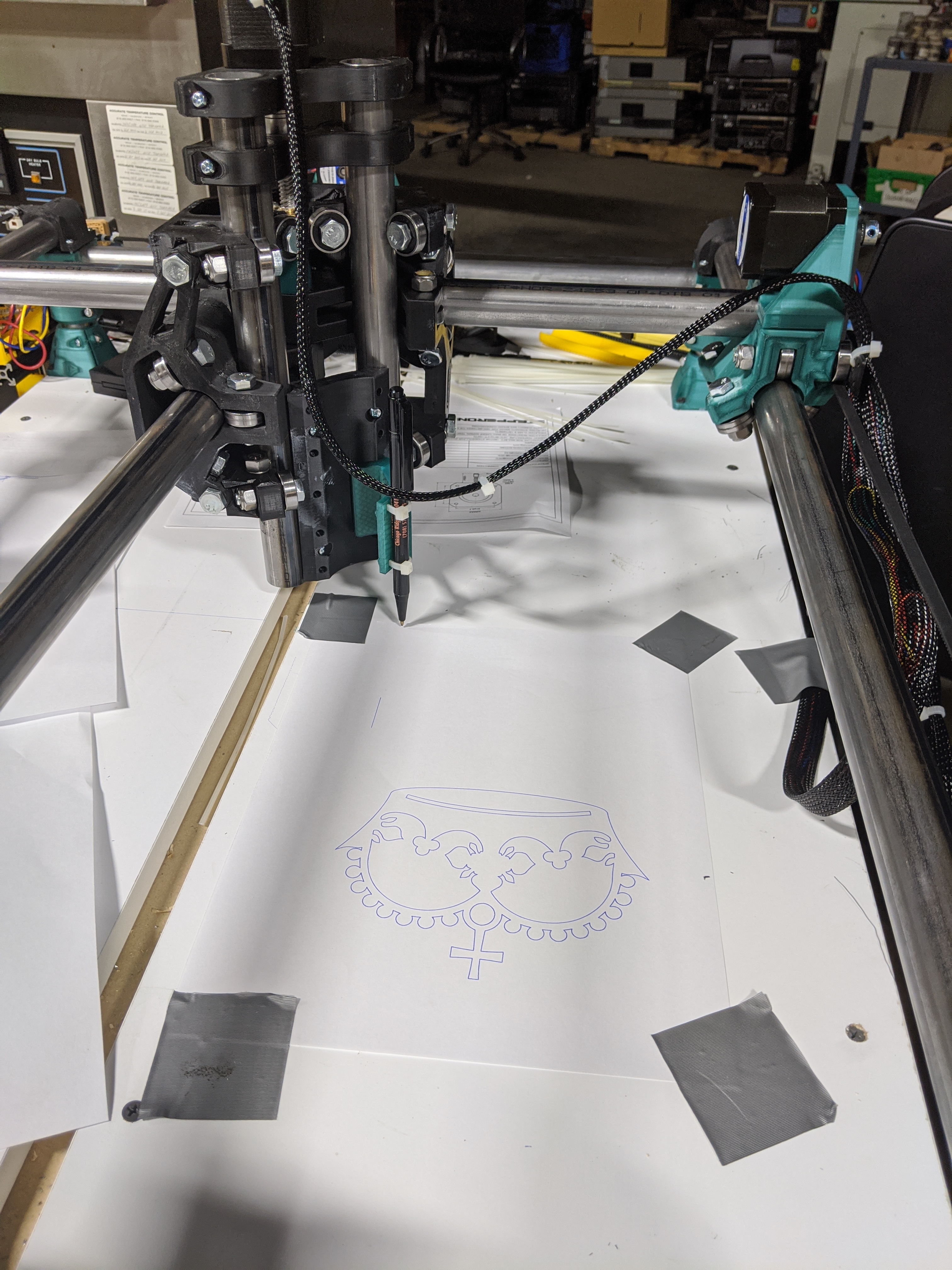
I still have to dial in my control as far as a z-axis it needs to know steps per mm, I’ve got it close but still not there yet…
6 Likes
It shouldn’t be a calibration step. The leadscrews move 8mm for one turn, 200 steps/turn and 16 microsteps/step means 400 microsteps/mm. On the Z especially. If you have a slight offset, something else is wrong (and it may be in the way you measure not in the machine).
Again, I am interfacing with an OpenBuilds black box.
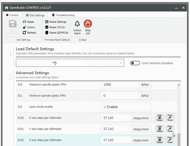
It had defaulted to 200/mm across the board, way off, on the belt drive - used the Calc Steps button and it figured it at 57.143.
For the z I have to check the microsepping on if it is 1/8 or 1/16
200 steps per rotation, at 1/8 microstep = 1600 step per rotation
One rotation = 1600 steps per 8mm (pitch) but we need steps per mm. So 1600 / 8 = 200 steps per mm
At 1/16 microstep correct, it would be 400.
Also there is a fine tuning wizard built in to the control software, I need to look into that, need to draw some 1" -??" squares and measure to see how close the x & y are performing.
I’m just ecstatic that after 8 months I have something that resembles a crown.
I must also add that I am impressed with the control software that drives the black box, the xyz readout is cool, it traces the path as it runs, zeroing the unit out is easy.
All in all, something a dummy like me can pick up and run with easily (in theory!).
I’ve never used that software, or box, but the steps/mm thing comes up a lot. Some people do just measure and then tune. But I am against it because it can mask real problems.
The screw driven axis really should be closer to 200steps/mm than anything you can measure (assuming 1/8 microstepping). I would argue any errors are in other things flexing or your measurement procedures than the accuracy of a leadscrew.
On the belts, they have 16T pulleys, 200 steps/mm and 2mm/ tooth on the belt. At 1/8 microstepping, that is 50steps/mm. The belts aren’t as accurate as the Z leadscrew pitch, but they shouldn’t be 15% off. If you start cutting a 1" square and then tune it, you might end up with 52steps/mm. Is that because the belt is stretched, or the CAM was fast and deep and the bit flexed? What happens later when you dial in your CAM and add a finishing pass and the results are worse?
There’s plenty of reason to measure and plenty of reason to tune. But I would leave the steps/mm at their theoretical values until you understand which component is causing the error. For example, if you can measure your belts are 2.05mm/tooth, by measuring a bunch of them, then that is a good thing to compensate with by steos/mm, unless you can fix the belts.
1 Like
I’ll be back at it tomorrow, I’ll reset the z to 200 and try to accurately move and measure and get that locked down somewhat. Or at least satisfy myself that it is “close enough” for what I anticipate to be mostly 2D work.
I plan on staying in “pen mode” for a bit, just to see how close / far off things actually are in x-y land.
The first crown attempt (with the x & y set to 200 steps/mm) freaked me out, and it was a quick OMG abort, and then to figure out how things could go so wrong so fast.
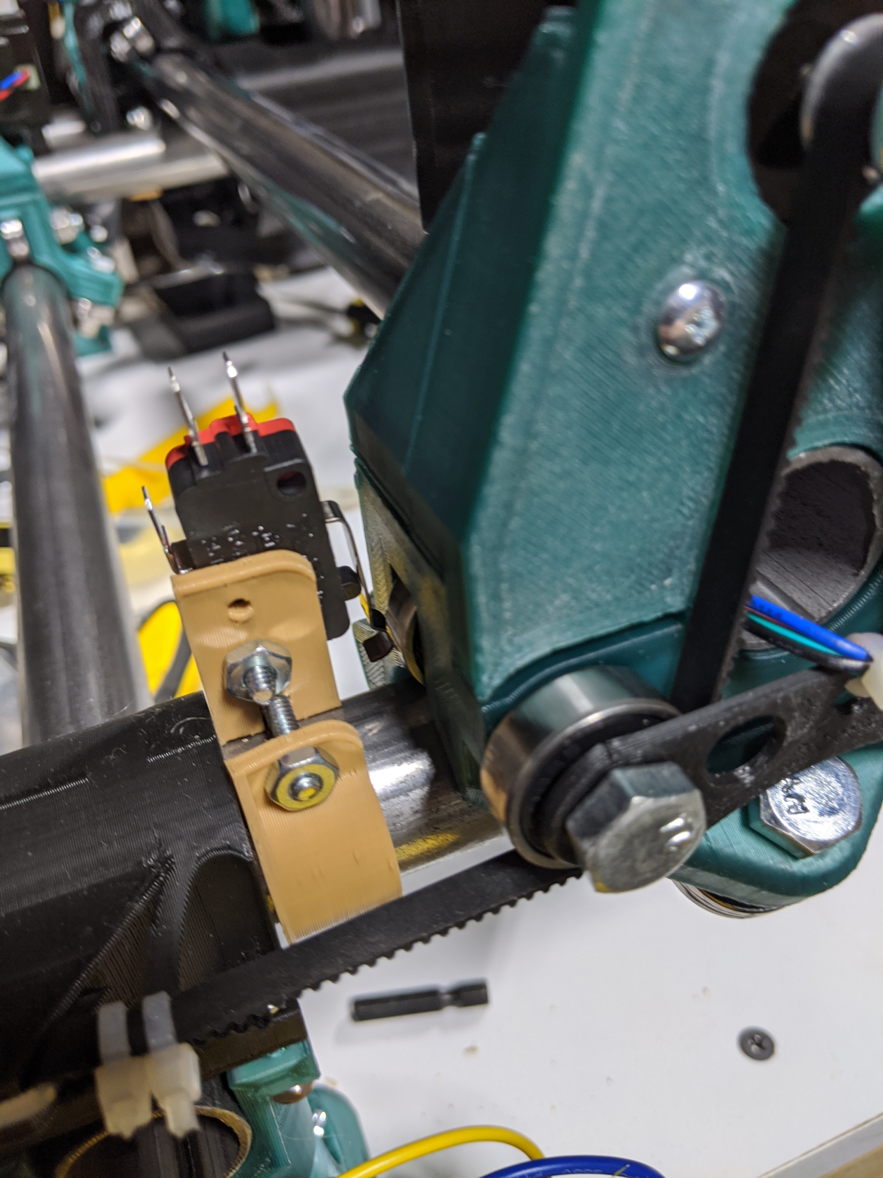
Next up we’ll install the end stops, ( I’ve already crashed the pen into the wall a couple of times, do not want to witness a power tool doing that), mount the dewalt, cut out the sacrificial spoil board and get a real one put in there and then start getting things dirty.
To be honest, in the short term, it just needs to be accurate enough to cut my 611 & y-plates  . But I do appreciate your input, and I am not striving for perfection here, - well always striving but knowing that perfection may not be possible.
Again, I wish to thank you for your responses.
1 Like
You were correct on the z
Z is within one mm over 100 mm range
X and y were .3 and .5 mm off over 100mm range
I think we’re close enough for government work
1 Like
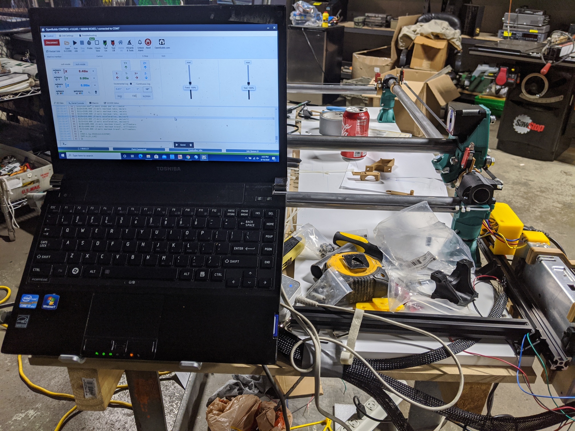
Moved the control and power supply.
Installed limit switches (waiting for shielded cable)
Mounted laptop.
2 Likes