I decided since I like spending all my money on this stuff I would pick up some new 2209’s. Added functionality, more current for my beefy lil 17’s.
2208 and setting up firmware was already giving me problems. Why not?
Got the 2209s today and after hours of trying to compile other people firmware setups and trying to compare and contrast between them and match up versions I said screw it and started fresh from Ryans MPCNC_Ramps_T8_16T_LCD_32step_DualEndstop
It worked! Currently have everything working correctly, all motors in sync and working, xy directions, UART, endstops and trigger status, homing using endstops (dont home z not fun).
I have all my end stop blocks as close as a 3am wood scrap can be.
This forum has been incredibly helpful in this journey so far. I rarely have to post looking for answers because there is such a wealth of trial and error documented here. Makes the process a lot easier. Thank you all for paving the way!
Calling it a night tonight by attaching the pen mount, hopefully tomorrow brings some crowns!
Test printing (carving?) the crown!
Everything seems to be working as expected so far! Question you will see in here some areas it goes slow and controlled, some areas it just speeds off real quick. Doesn’t affect output quality too much. Before I start diving into settings, anyone has recommendations or bets on what it might be or what to check?
Honestly, this is one of my favorite stages of a build beyond the final stage just making stuff. Right after its all started working and you get to start fine-tuning it till its perfect.
This is my own customized version of Ryans MPCNC_Ramps_T8_16T_LCD_32step_DualEndstop
customized just enough to get the SKR 1.3 / 2209s working in UART mode.
Everything else was pretty much the same as Ryan originally set it up.
You can see at 0:32 seconds on the video above what I am worried about. I think that was suposed to be a smooth curve. Again in the corner at :51.
Now I am using Stealth Chop on all axis, 16 micro-steps, HYBRID_THRESHOLD is turned off.
Think it can be the 16 micro-steps? I can probably bump those up to 32+ is there a loss of torque with high micro stepping? I see it does not really increase positioning accuracy but it does help to lower torque ripple. I bet it would help in this low load application but when I throw a router on going at wood would I want lower steps to get more torque?
Not sure how to estimate the required torque under that kind of a situation, then again it probably widely varies work material / aggressiveness in your tool path and even type of bit you are using.
Using these motors with a Holding Torque: 59Ncm(84oz.in) how high of a micro-step would I want to set a basic wood setup to get optimal performance in both torque and positioning? Although I guess the benefit of 2209s is that i can easily experiment with that when the need applies.
Main goal I think I’m going to print some squares and do my measurements to see how close things are coming out before worrying about these little ripples too much
This pattern has a bunch of tiny and large arcs (G2/G3). I think it is slowing down on the tiny arcs, because it is trying to make an arc with hundreds of points, which works fine on the large arcs, but slows down on the tiny ones. I don’t think it has anything to do with your steppers or drivers or torque. I don’t think Ryan’s crown uses arcs, so that is a good test. Does your firmware have a number version in it? 415? 418?
I’ll try out Ryans Gcode when I get home and see if I get different results.
I’ll definitely take a look and read through it on my lunch today.
Just in case anyone gets bored ill upload my firmware and gcode tonight for people to take a peek at if they desire. (all changes in firmware will be marked with a comment.)
If you do a search in each config file you can easily see all my changes.
I have also included “Read Me For Details SKRV1.3.TXT” In the firmware project root that explains this and my machines set up.
I would not recommend using this on your set up unless you read through and understand my changes and it matches your build. But it is fully compiling for me on VScode and PIO latest versions.
You need to use version 418 or above for the firmware, and you gcode is not correct you do not have rapids set or even in the file. Have a look at the estlcam basics.
Thanks @vicious1 . Figured out some of the issues last night.
One I missed the step of unchecking g2 g3 in etslcam settings. That helped allot. Then I was printing about double size so adjusting steps/mm helped that out. What do you mean I don’t have rapids set?
Y/Y2 work great, X /Z work great, X2 is doing something funky. It seems like both X/X2 are moving in the same direction but it almost seems like x2 is moving faster then X1. After about 10 mm it starts to slip.
In 418D are we still assigning E0 to a unused and shifting E1/E2?
Where is X2 = E1 and Y2 = E2 defined in the firmware?
Ok so it looks like X2 is not being defined or activated properly.
Both x and x2 respond to x movement, X2 travels about double the distance of x. Everything else that I can test at the moment seem to be working appropriately.
Yep Configuration.h #define X2_DRIVER_TYPE TMC2209
Sorry for the late response, I have been tied up with adulting.
I have defined the drivers and set E(X) pins. Everything including Y2 is working but not X2. Is there a place in marlin 418 that defines X2 = E1 or E(x)?
Marlin just uses the next available driver for X, then Y, then Z. So if you have X2 and Y2, and E0, then X2 would be E1 and Y2 would be E2. It does this with macro math.
Sorry its been awhile since I have updated the build log. I have mostly been contributing on the FB group since I’m generally on there more often.
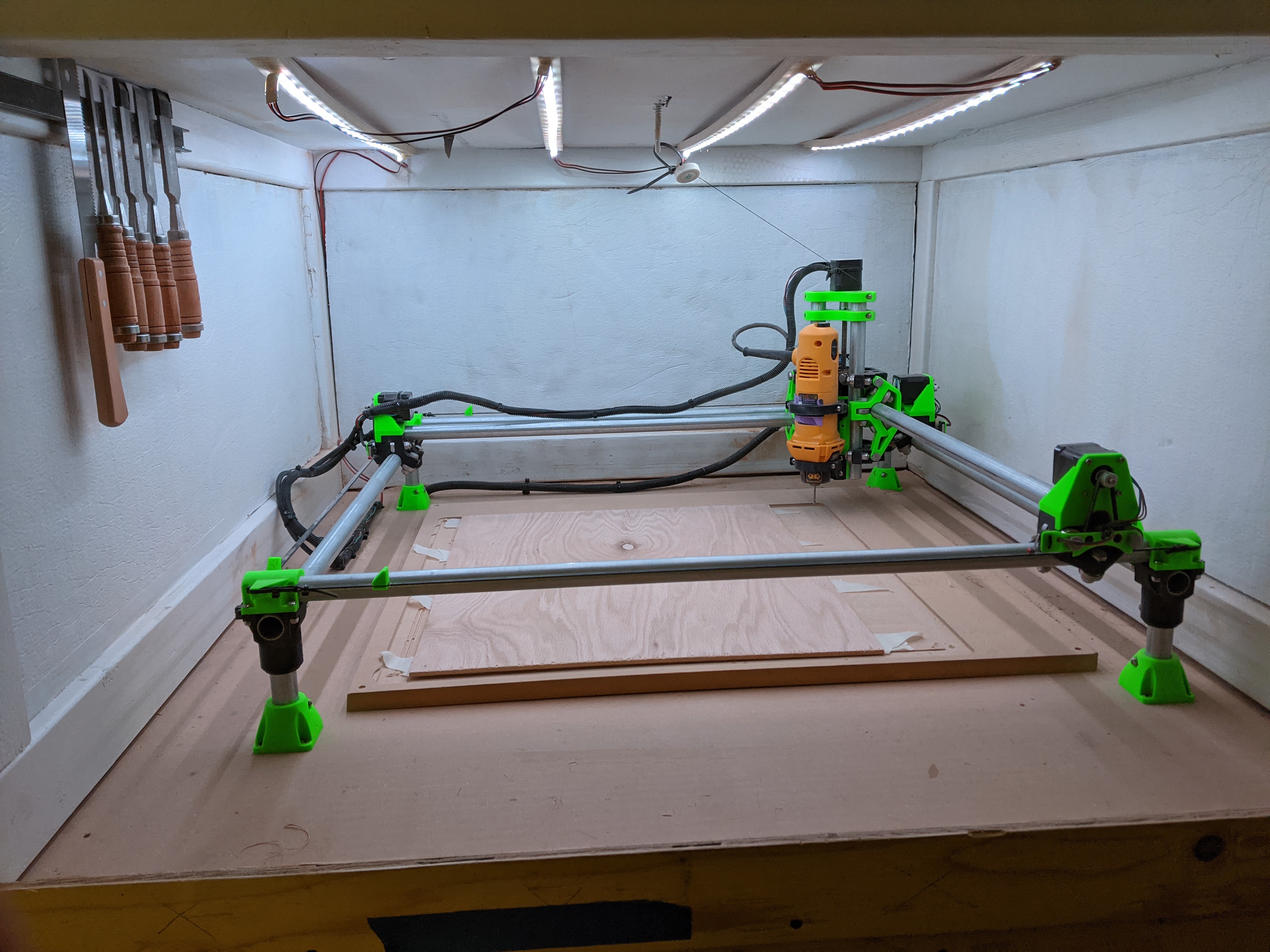
Update: Build is pretty much wrapped up. Ended up building a enclosure for the unit after making a mess trying to surface the bed. Hindsight says I probably should have just figured out a dust shoe set up.
I am using the SKR 1.4T with 2209s Dual ends tops and everything works great on that. For Z cables I ended up picking up a old ID card swipe holder thing. Basically just a pully to hold the cable up as it moves around.
A few other goodies I added on and its been a great machine. Although I think I’m about to tear it apart and upgrade to primo!