New Build - Sydney Australia

Hey all,

Wanted to keep myself honest and let everyone know I’m working on a new build. I’m based in Sydney, Australia.

So far have printed all parts, have bearings, nuts and bolts and base to build on. Also bought a Makita router to use as the initial tool. I’m working off the F design and using 25mm aluminium tube from Bunnings (2x3m lengths).

Working on constructing a workbench so I can start doing some assembling. I’ve partially assembled trucks just to test out the fit of all the components and it’s looking spot on so far.

Will post a few pics when I have the workbench done and started mounting to the base.

Electronics and motion components are a little bit slow going as they seem slightly harder to source the right sizes here. It’s definitely possible to go the aliexpress route but I’d rather find somewhere local.

Cheers,
Gritters

5 Likes

Here’s the pricing and parts breakdown so far, if anyone is looking to replicate this in Australia.
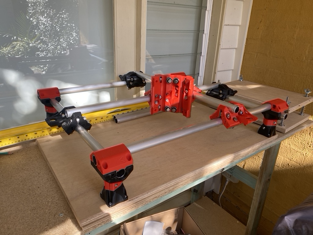
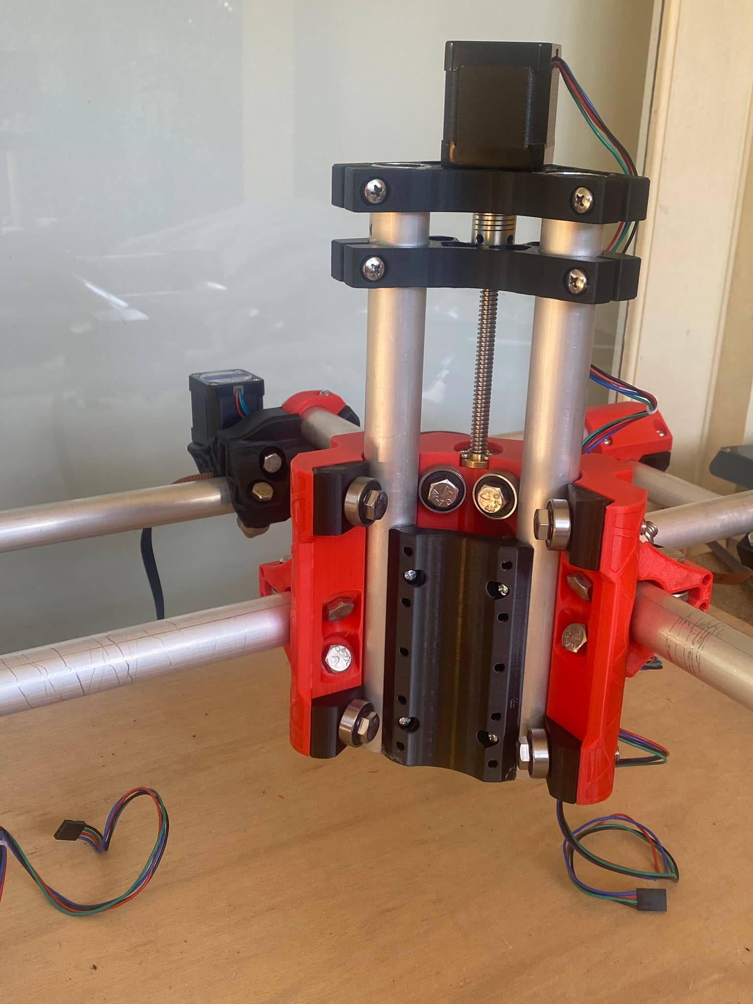
I’m building an F model, with 25mm conduit. Initial build is default sizes as per the MPCNC calculator,
450mm x
330mm y
81mm z

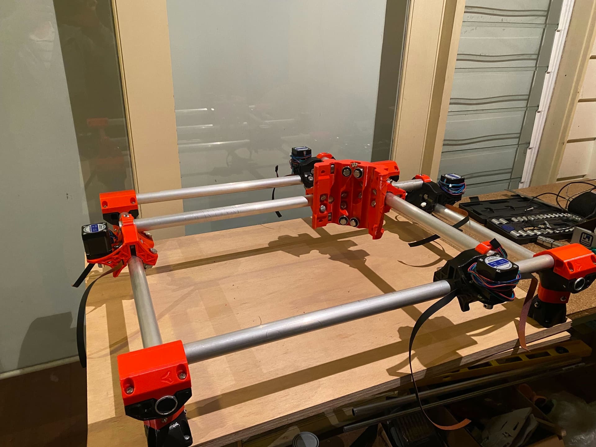
MPCNC parts printed using an Ender3V2, ESUN PLA+ red and black filament from Jaycar. $39.99 per spool,
Total - $80

Conduit - Metal Mate 25mm x 1mm x 3m - 2@$27.21
Total - $55

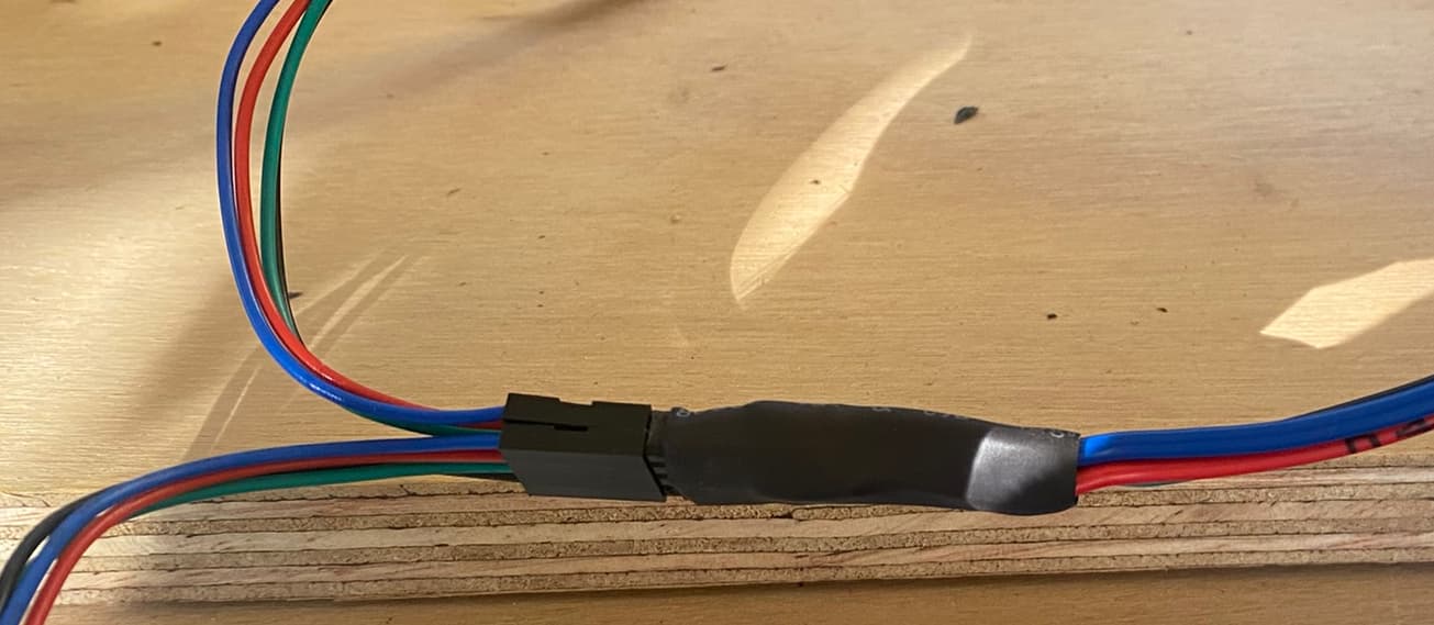
Stepper Motors - AliExpress
[5PCS Nema 17 Stepper Motor 4-lead 48mm 59Ncm(84oz.in) 2A 1m Cable (17HS4801) Nema17 Step Motor for DIY 3D Printer CNC Robot XYZ] -
Total - $79

Bearings - ebay, [10pcs/set 608-2RS Rubber Cover Sealed Shafts Deep Groove Steel Ball Bearing H4AU] - x6 pcs,
Total - $31

Hardware - Konnect AU -
|Hex Head Bolt Stainless Steel DIN931 G316/A4 M8 x 40mm|50|$0.46|
|Machine Screw Stainless Steel Pan Head Phillips G316/A4 M3 x 10mm|30|$0.10|
|Machine Screw Stainless Steel Pan Head Phillips G316/A4 M5 x 30mm|70|$0.55|
|Hex Lock Nut Nylon Insert Stainless Steel DIN985 G316/A4 M5|70|$0.06|
|Hex Lock Nut Nylon Insert Stainless Steel DIN985 G316/A4 M8|50|$0.15|

Total - $84

Makita Router - Bunnings - model RT0700CX
Total - $269

Pulleys, Timing Belt, Idlers - AliExpress
LINK CNC GT2 Timing Pulley 16 teeth Bore 3.17mm 4mm 5mm 6mm 6.35mm for 2GT Synchronous Belt Small backlash 16Teeth
5mm, 10mm, Silver
AU $0.64x5
LINK CNC 3D printer 2GT Open Timing Belt width 9mm 10mm mute dustproof For Motor
10mm, RF dustproof
AU $1.87x4
LINK CNC 2GT 20 Teeth synchronous Wheel Idler Pulley black with Bearing for GT2 Timing belt Width 10mm 20teeth 20T
A bore 5mm, silver, For belt width 10mm
AU $0.76x10
Total - $33

Couplers - AliExpress
4pcs Aluminium CNC Motor Jaw Shaft Coupler 5mm To 8mm Flexible Coupling OD 19x25mm Dropshipping 3/4/5/6/6.35/7/8/10mm
5x8
AU $6.32x1
Total - $7

Lead Screw - AliExpress
3D Printer T8 Lead Screw Trapezoidal OD 8mm Pitch 2mm Lead 2Mm 8mm 200mm 250mm 300mm 350mm 400mm 450mm 500mm with Repair Nut
Pitch 2mm Lead 8mm, 300mm, China
AU $7.40x1
Total - $8

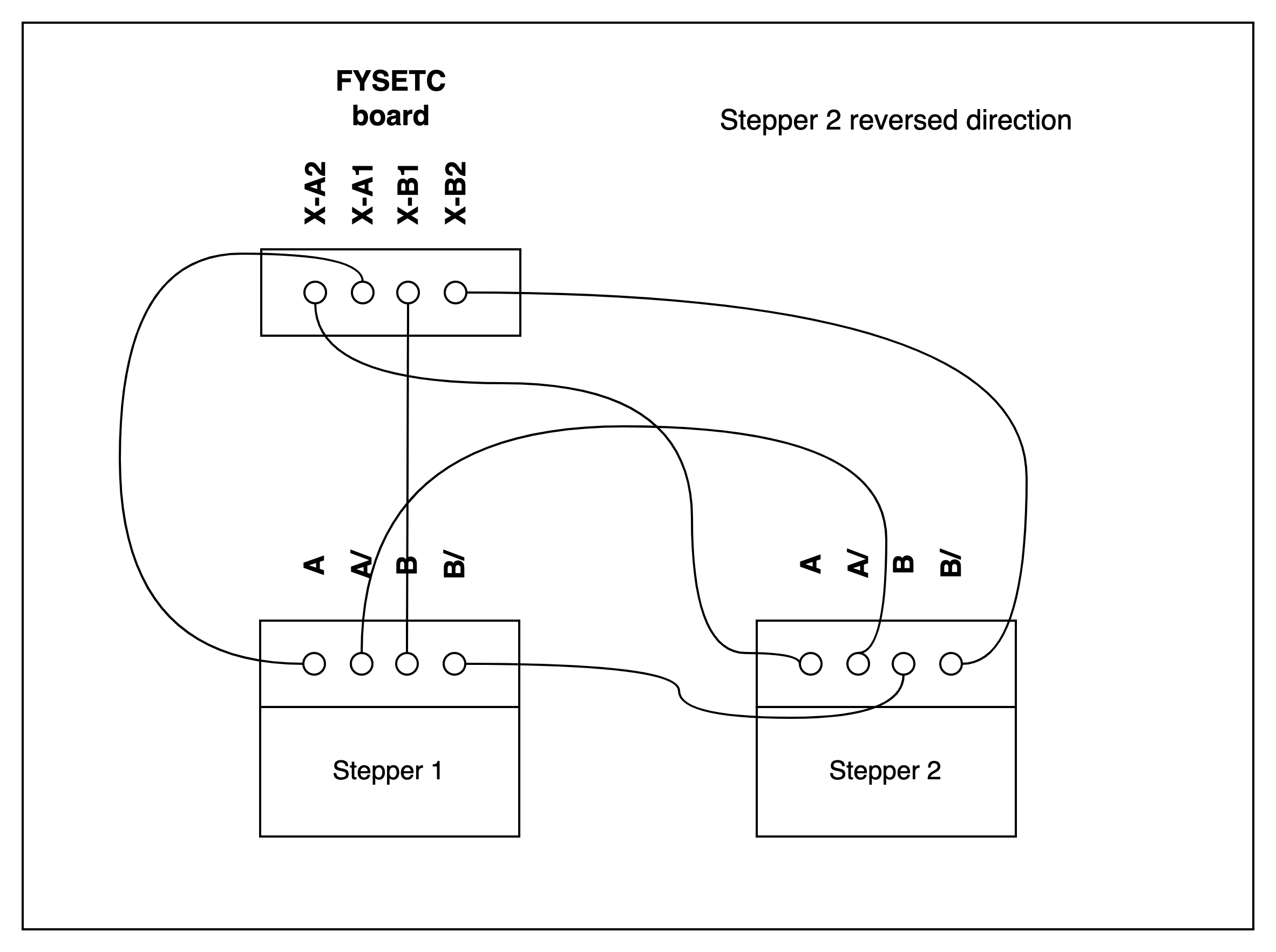
For a controller board I’m using a mates FYSETC with FluidNC so far. Have yet to test this out with the steppers.

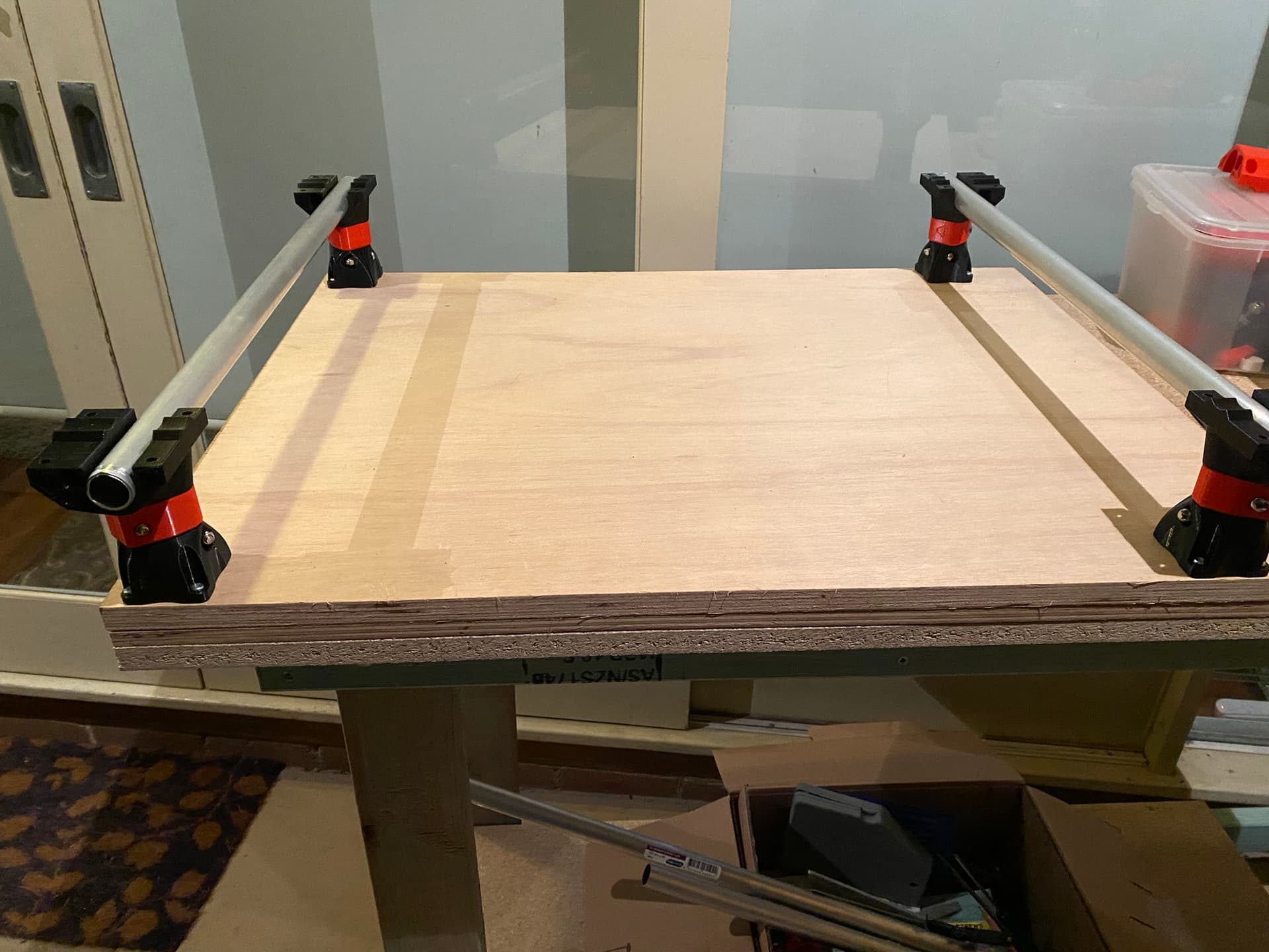
For the base board I’m using Marine Ply sheets from Bunnings, 18mm and 12mm. Total - $120

Total cost so far $766. Not expecting that to increase significantly from here as all parts have now been sourced.

3 Likes

Quick update - base is done. Perfectly level and all fits together well.

The only issue I had is that my lock nuts are slightly more rounded than the nut holders on the 3d printed parts. This makes them tough to tighten, as you can’t get the socket in around the nut once it’s tightened below a certain level. If I use the 3d printed parts to provide the torque on the nut, the part rounds off quite quickly. Doable, but not looking forward to a lot of these.

Now waiting on a bunch of components to arrive before I can assemble the trucks.

3 Likes

I had to wedge a flat blade screw driver in there to tighten some of mine. Remember that they are printed plastic parts so you don’t want to over tighten and crack parts. That happened to me as well but luckily it was on smaller parts. Good luck!

1 Like

Pipes all cut. Trucks are assembled with bearings but no motors. Today will assemble the core.
Will also track down tool prints for a 25mm build with a Makita router.

Am waiting on AliExpress delivery for my stepper components so am currently unable to finish the trucks and belts. Also waiting on a Pololu crimping tool so I can make up the series cabling for the steppers.

Some extra costs in the mix:

Tube Cutter - Bunnings - https://www.bunnings.com.au/trojan-3-piece-tube-cutting-set_p0331098 - $25
JST/Dupont Crimping Tool - Pololu/Core Electronics - Crimping Tool: 0.1-1.0 mm² Capacity, 16-28 AWG | POLOLU-1928 | Core Electronics Australia - $75
Dupont Jumper Kit - ebay - [620x Male Jumper Pin Dupont Pin Crimp Wire Housing Kit Header Female Connector] - $14
JST Jumper Kit - Jaycar - Connectors Kit with Popular JST XHP and PH2 Headers | Jaycar Electronics - $20
4 core alarm wire - Jaycar - $8

Total so far: $908

4 Likes

All that can be done without motors being attached. One sad truck in red because I ran out of black filament :slight_smile:

4 Likes

At least you know where the front is now. :stuck_out_tongue:

3 Likes

Old mate Ali Express delivered my pulleys, belts and idlers today so I connected up all the trucks, motors and belts.
After the first fail with the lock nuts rounding out one of my parts during base mounting, I’ve been pre-threading all the lock nuts entirely to try and avoid a repeat of the problem. However, I still managed to round out one of the gantry clamp nut holders on a truck. I’m either going to try to salvage the truck by widening the hole so I can get a socket in there, or will fall back to a truck reprint.

One trick I found useful while trying to prevent the problem was to use an extra M10 screw, with the lock nut threaded backwards on it just enough to keep it held. Then use this extra screw to push the lock nut as far up the hole as possible, while tightening the correct screw until it engages the lock nut and then eventually pushes the extra screw out.

Trucks seemed to be squared very close (<1mm) but I wasn’t entirely sure I was understanding the purpose of the truck squaring step. Reading ahead the core squaring seems to make more sense so I’ll see if we are still close to square at that point.

Obligatory pic of motors, gantries and core all attached, with belts loose. Z axis tomorrow, but won’t be done as I’m still waiting for a coupler delivery and my wiring crimper.

Must give kudos to Ryan for this design. I’m perpetually amazed at how easily everything fits together and how well it’s been battle tested and documented. Apart from my rounding issues everything has pretty much worked like assembling lego. Awesome stuff!

2 Likes

no salvage of the truck possible so we’re reprinting. The lock nuts I have are very very tight which is likely the problem here. Wiring should be done today if the crimper shows up.

Truck reprinted and reassembled.

Have crimped the first stage of my serial wiring - JXT 4 pin to dupont for the FYSETC board I’m using. I ended up using 24 AWG alarm cable and tinning the ends before just heating them enough to attach to the crimp. Crimping is awful for JXT with the Pololu tool I have, they are so tiny that without the solder you can’t balance them in the crimping tool.

Tomorrow will be the series 3 way cabling for one axis and we should be able to test some motion!

Today I finished up one of the serial looms. I’ve changed tack and am going JXT to soldered 8 pin header with all the serial wiring attached to the header. This allows me to attach both motors with their existing dupont/harwin connectors straight to the header, but also use some heavier gauge wire back to the board.
It came out pretty well and is quite robust, but the soldering onto the header is non trivial.
So was finally able to test out some X axis movement today :slight_smile:

Pic of the header and motor connections. Dupont and motors on the left, 4 wires in on the right, jumpers hidden under the heatshrink.

Wiring diagram for stepperonline NEMA17s, with one motor reversed, to the FYSETC board -

I did it with about 4 metres x 4 cables (AWG19) from the JXT connector, to one of these guys (chopped at pin 4).

The soldering is truly a lot of pain just to avoid chopping off the dupont/harwin connectors from the steppers, but I think (hope) it will make it easy to rewire later if I want to extend or reuse the motors. Plus I can use much stronger wire which should tolerate the movement much better than the thinner stuff I started with.

Last hurdle is that I’ve printed a makita toolholder which I found out afterwards uses a burly toolmount. I found out the hard way that the burly uses different nut sizes so I need to get some screws and nuts tomorrow. I’d prefer to stick with this toolmount as it has a decent vacuum connector. Not sure what anyone else is doing with primo vacuum connections for a makita, I may have to do some forum scouring.

Hope this dump helps someone :smile:

2 Likes

Z axis done!

3 Likes

First test, 30mm x 30mm square:

First obligatory test crown - pen wasnt quite low enough to kick in at the bottom:

Virtually no calibration required, everything just worked like it should!

4 Likes

@Ryan, WDYT about a fluid nc section of the forums?

2 Likes

Added! Great idea.

1 Like

@gritters, can you post this config in #fluidnc? I know it will help someone to have it front and center there.

1 Like

Absolutely! Just tweaking my z settings now and I’ll post it up. It worked out to be a great solution - the board is so so cheap, which is why I got it as a freebie :slight_smile: I’m not sure if it’s as stable as Marlin, but it certainly works for the basics for now.

2 Likes

https://forum.v1e.com/t/primo-config-for-fysetc-e4-board-with-fluidnc/33993/2

I have this working perfectly now, it was a pretty arcane issue with fluid and the TMCStepper library that took me a bit of time to pull apart.

Now its time to hunt down some dust collection and maybe make myself a cyclone, before I make a total mess of the backyard.

2 Likes

Where did you get your pipe?