I am try to the controls setup. I followed the instruction in the Docs page in this site. I’m using mini-rambo 1.3a from this store. I try setting up on 2 different computers to make should I wasn’t having problems with one of the computers. I could not get the step motor to move in RepetierHost or Esticam. I’m using win 10. any advice
If you tried estlcam, I may have tried flashing the board for you. We only use estlcam for the cam, not the control. Does repetier see the board?
When press connect it shows to be connected. I checked printer info it shows unknown and no firmware is listed. when I use the controls it says command waiting and then it times out. How do I check to see if the firmware is flashed to the board?
Do you have a screen installed?
I got a blank screen when installed. I switch the connections with the same results. I was wanting to solve ! problem at a time.
I tried to connect the wire in different ways as stated in a post at this forum sometimes the will light up with nothing on the screen and other times nothing happens
Did you get the screen from the store too?
There are 4 ways to plug in the LCD. Swapping the cables (like putting your left shoe on the right foot) or rotating the cables in place 180 degrees. Sometimes the cables are keyed, and it seems like they choose a random direction for the keying, because it is often wrong.
Common problems connecting from repetier host:
- Repetier server is installed
- You have the wrong port
- You don’t have the 12V connected, just the USB
- You have the wrong baud rate. It should be 250000
I bought the screen from the store. I do not have Repetier server installed. Everything is connected right and have a green light on the board.
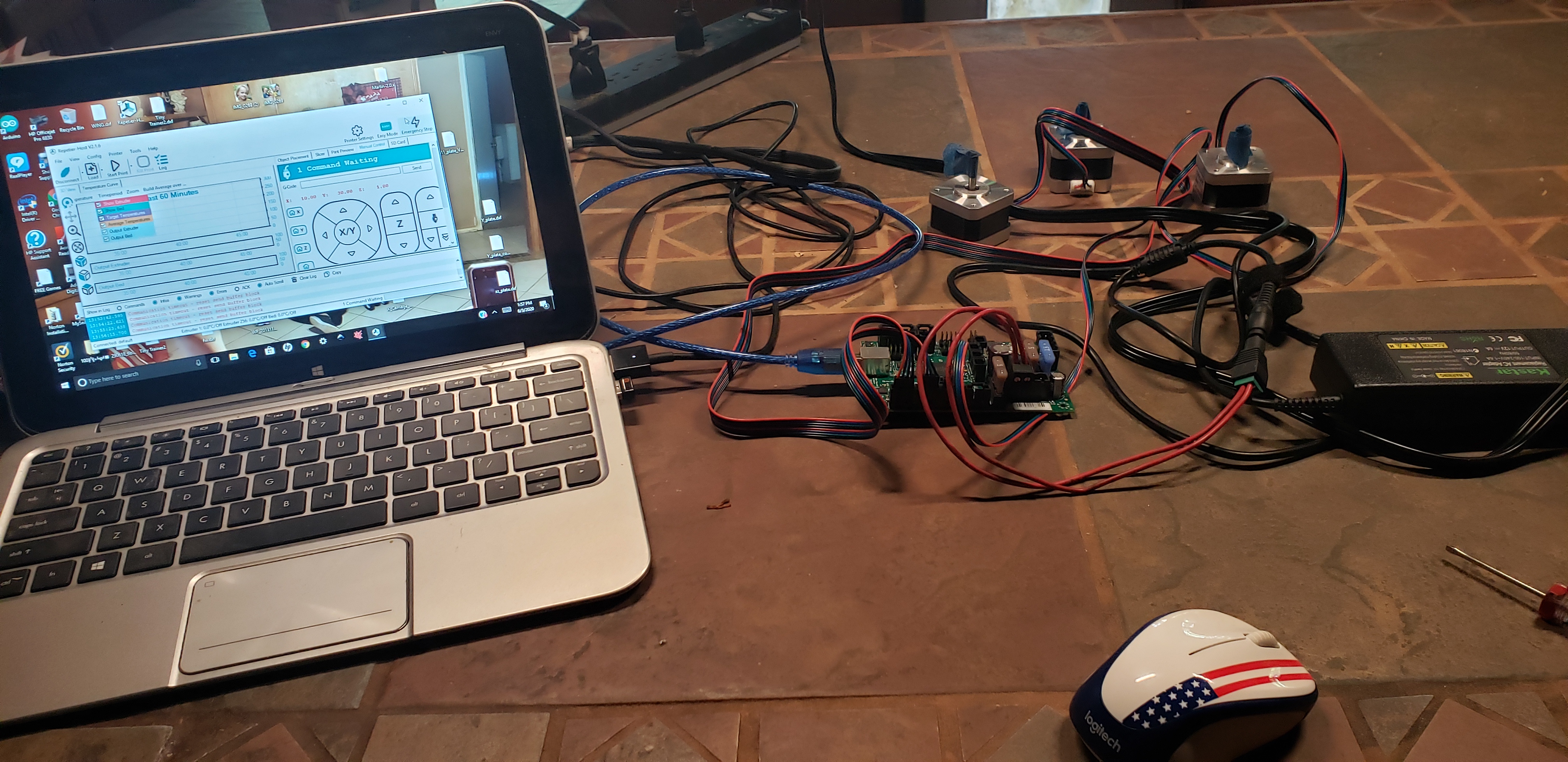
Can you share some photos? I am interested in seeing the wiring, and also what repetier host looks like when you try to connect.
If you flashed from estlcam, then the lcd won’t work and repetier host won’t connect. But I think that is pretty hard to do with the rambo.
If it isn’t something simple, then you can flash it again, but I’d like to know we’ve checked all the simple things first.
I did not flash it with Estlicam. I just try to see if it would see it. I did not do any upload to the board. I am trying see I can control the step motors. I have not connected it to the LR yet
Are you sure the 12V is wired the correct way?
It is wired correctly. I bought the power supply from this store.
I dunno… I see a barrel connector inline there… 
The connector came with the power supply. I checked the fuse and there is 12V thru the fuses so the board is getting power. If I have the power connected wrong then the board or the power supply is labeled wrong
Sorry, didn’t mean to imply that you had done anything wrong, per se. I know Ryan has had trouble with those connectors in the past, and has considered removing them from the kits altogether, and just have people wire directly to the power terminals. It was a bit of an inside joke, akin to concrete-filled rails and other shenanigans. If you’re getting power to the board, then there’s no reason to think that’s an issue, yet.
I can’t quite tell from the photo. It looks like the power connector is plugged into the main - and bed +, rather than main + and main -. But that could just be a bad angle. I can only see one open terminal pin between the power connector and the capacitor at the edge of the board. There should be two (the heated bed supply).
I understand. Since I’m using as a 3D printer I don’t need bed wired, is that correct. If I need to reflash the firmware I will do that. I have not flashed the firmware since got the board here.
.
You shouldn’t need to reflash the board. I’m concerned about how the power supply is connected to the mini-Rambo. Again, it could be the angle of the photo, but it appears that it’s not plugged in to the correct terminals. The power terminals are main -, main +, bed -, bed +, in that order. I appears that you have the power going to main + and bed -. Which may be OK, if everything is on a common ground, but it would probably be better if it was actually plugged in to main - and main +. Again, if that’s the case, and it’s not just the photo angle causing me to see something that’s not there.
I guess I don’t understand what your are talking about. There is a plug that plugs into the board for the power, that is where I connected the power supply. That plug was already installed. It said that for the bed another plug was needed.
From the image it looks like it’s plugged into the middle of the 4 power inputs. Should be on the left two looking at it like in the picture. I don’t think the mini needs all 4 powered, the full size needs them. If it were me, I’d reflash the board. Estlcam used to automagically flash the board when you started the control part of the program. I don’t know if it still tries or not.