The Nxx and *xx are line numbers and checksums. They get added im to prevent noise from getting in the way so the firmware can validate the commands. The part in between are the actual gcode commands
Thanks for that info, I didn’t know that.
Any indication what is holding up the machine? Would it help if I posted screenshots of my Estlcam/Repetier settings or is this something that can be figured out if I post the entire GCODE?
Sorry, I don’t have any experience with editing gcode manually…just taking what my 3D printer slicer outputs
Sorry to make another post so quickly, but the fix is to DISABLE “Use arc commands G02 / G03…” in Estlcam Setup → CNC Programs
Somehow I missed Ryan’s third comment in the EstlCam Basics mentioning this. I was just going off the settings I saw in the screenshot, and someone on Discord pointed it out to me
Sorry to waste your time troubleshooting my bad configuration.
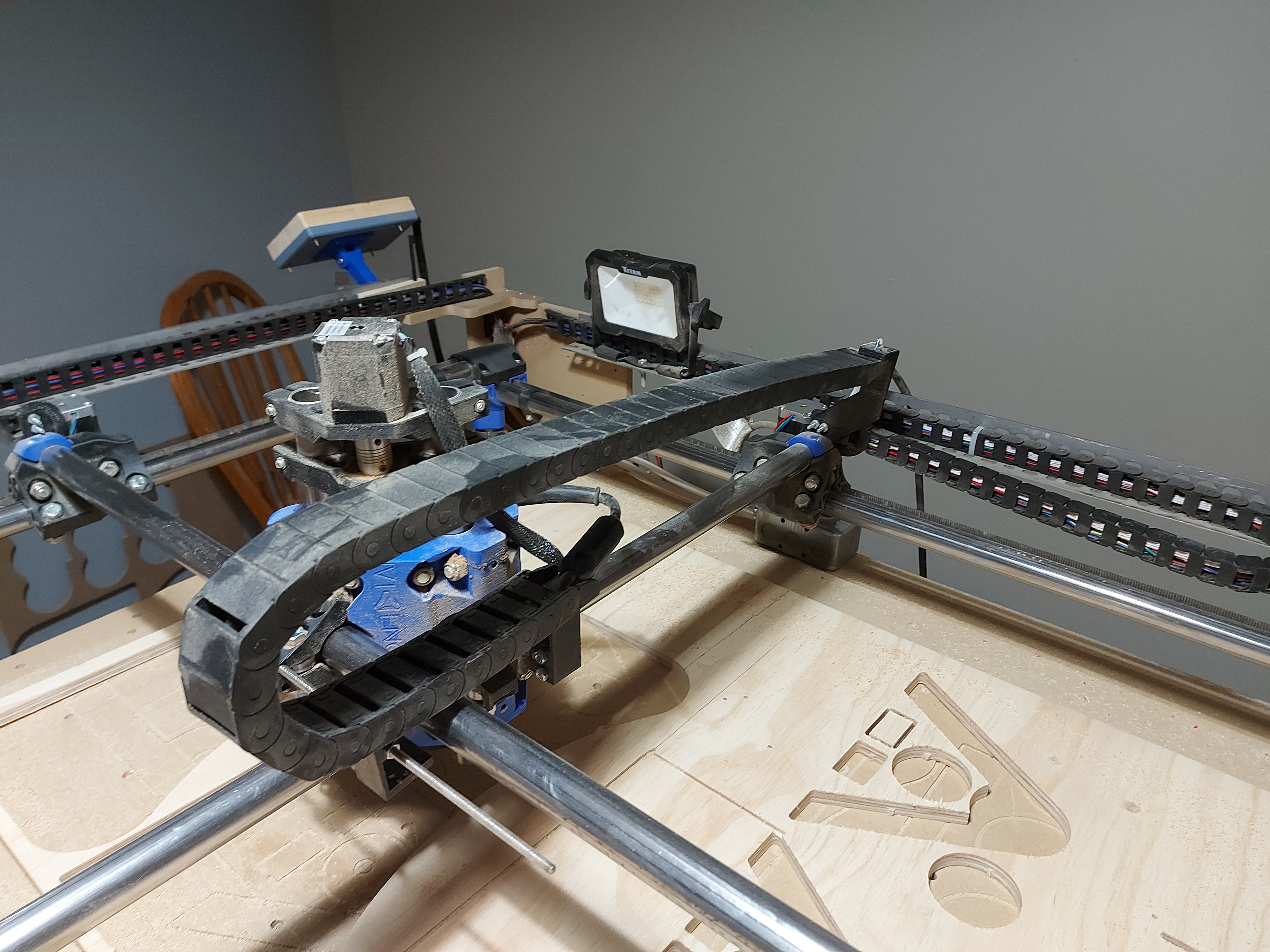
I’m going to setup some drag chains, but I have a question.
I read all over that you should not mount anything to the Z-axis, especially if you want to try machining aluminum. There is a nice drag chain mount that I found here but is that not recommended?
If not, what are other options for mounting?
Generally the recommendation is to connect to the core rather than to the Z tubes as connections to Z tend to apply forces that negatively impact the tool’s alignment to the work.
There are some extra holes in the Primo core for just this sort of attachment. I’ve got a Burly myself, but haven’t had a lot of time recently to finalize my wire handling and dust collection connection.
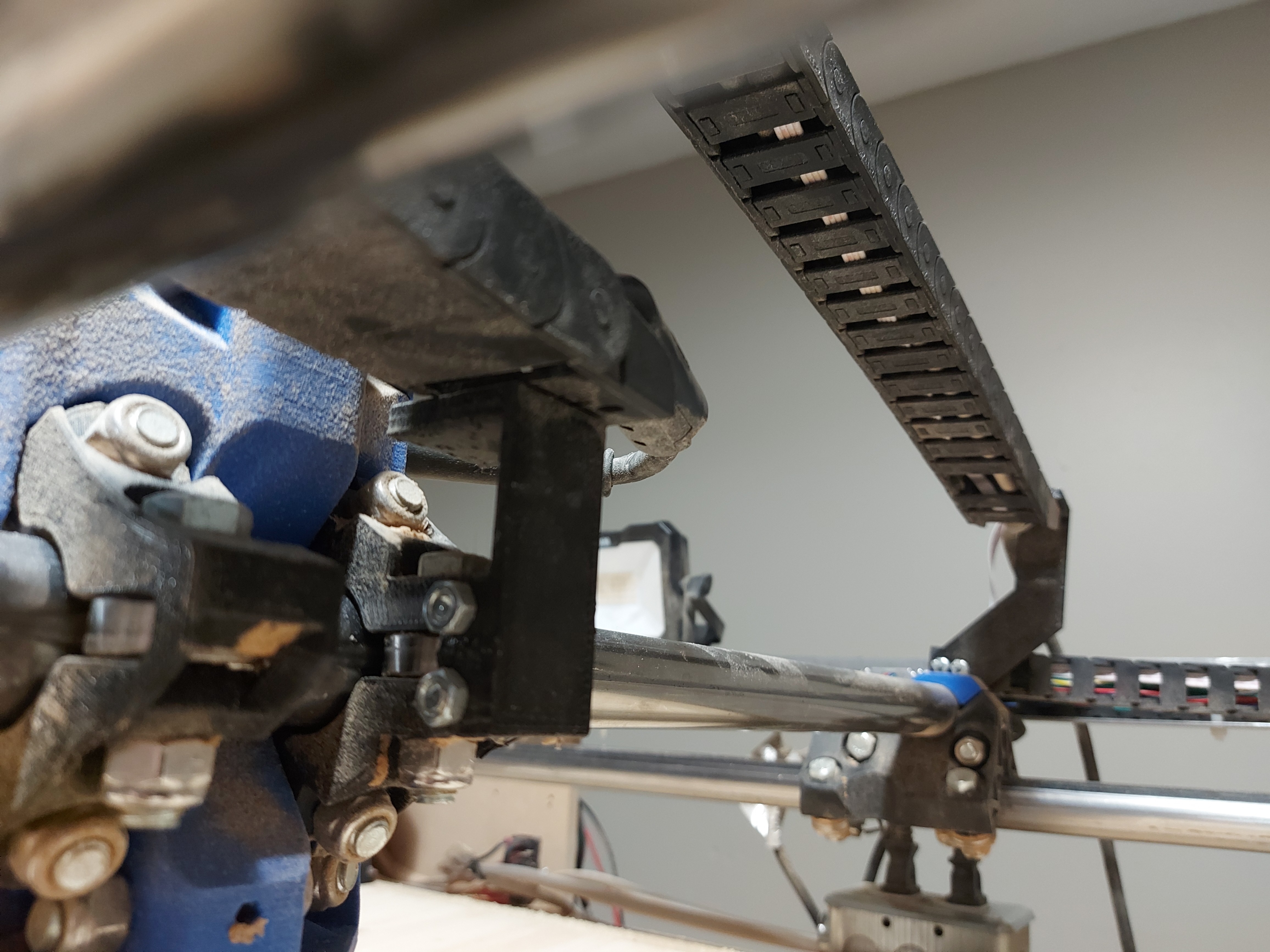
The core end is just a small platform with 4 “ears” that attach to the core clamps 5mm holes. The other end is an expanding plug with a tower to hold the drag chain.
Its for spacing the drive pulley on the motor shaft. As for the name, I think Darryl was one of the runners-up in the naming poll for the new version of the MPCNC that became the Primo. Also, I think it’s the V1 goat’s name.
It clamps into the top of the tube. There are tons of ready to dl stl files for mpcnc z chain mounts. I suggest combing over a few before making a final decision. No need to grind the f360 axe on this one.
The top of the Z tower has a very large mechanical advantage over the Z axis. It doesn’t take very much force at all up there to get the Z tower to tilt. Nothing should be clamped up there that has any sideways force on it whatsoever.
Yes, you can probably get away with it. The core is probably strong enough to keep any tilt there from being something that you notice.
When we start looking for any way that we can to increase the rigidity of the machine, leaving anything clamped up there is like trying to reduce weight in the car by removing the spare tire… while leaving a 300lb anvil in the trunk. Seriously there’s nothing on the MPCNC that has greater mechanical advantage on the Z axis with the possible exception of the top of the Z motor. Even the very best of drag chains has some resistance, not to mention the wires that go inside it. In this case, that appears to be a 3D printed drag chain, and in my experience those are far from the best in low resistance drag chains.
Because I felt that I was already pushing the limits for my machine just by having a larger working area, I decided that the top of the Z tower was absolutely off limits for mounting anything. The only thing that goes up there is the wires for the Z motor, and that’s basically because they have to.
Yep it is not ideal due to that. Really the z chain should be mounted directly to the core tbh… just too complicated a design for the time I was willing to put in. The reason for that was after running my machine initially… it felt so dang solid I thought the little outside load would wash out. Also, I have a 2.5” flex hose that pulls quite hard on the z when turned on… that is a much larger load than the chain. I haven’t found a way out of that one yet though… another dude on the forums here did attempt to design a vac flange that mounts to the core (brush does not move with z either). That method is the best way, but I just did not like a few things about the execution on that model is all.
Etymology of “Wire Daryl”:
As the naming for the Primo was being discussed, there were a couple of joking references to “I’m Larry, this is my brother Daryl, and this is my other brother Daryl” from Newhart. The name didn’t win the poll competition for the machine, but @vicious1 made it in to an inside joke for these parts that come in pairs on the Primo.
The Y tower part offsets a little too far actually. I’ve been meaning to fix it, but since it turned out that the drag chain mounts are 90° from where i left the holes (I drew these up before the drag chains arrived) mounting the chain off centre proved good enough to get a sufficient alignment. Then, as many things that I do as a “proof of concept” end up, it works well enough that I leave it alone.
I would recommend that you re-mix it and reduce the “dog leg” in the Y drag chain mount by about 2cm.
Edit: you may notice that the X drag chain mount there has the holes one way and the Y drag chain mount the other. When I got the drag chains for the X and Y axis, I got one that had the mount holes vertical and one where they were horizontal. You might need to do something different for your drag chains to X and Y