There are some steps you can take while you wait for your DRV8825 drivers to arrive:
Put your Ramps and your Arduino Mega board together.
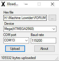
Upload the firmware to your board. I’m going to assume you are going to do dual endstop wiring. This does not mean you have to have endstops. It just means that each motor is individually wired to a stepper driver. To install the firmware:
Go here and download V1CNC_Ramps_Dual-2.0.7.2-src.zip file and UnZIP it to a directory. After UnZIPing, you should see another zip file and “firmware.hex.” It is the hex file you need.
Go to this topic and follow the instructions. Note the location and name of the HEX file has moved since I wrote those directions, so firmware.hex is the file you need.
If you have a display, install the display. I’m assuming that if you will have a display, it will be a RepRap display like this one. That is the kind of display that is configured in the firmware. If you need help plugging in your display, let me know.
At this point, you can test that the firmware is installed. If you have a display, you should see the menu listed when you power the board from the USB. You may have to adjust the contrast using the potentiometer on the display to see the text. If you don’t have a display, you can use Repetier-Hoist to talk to your board. There are instructions for setting up Repetier-Host for the MPCNC here.
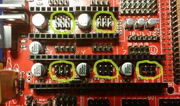
With the board completely unpowered, install your jumpers for your stepper driver. For each stepper driver, you want a jumper for all three (MS1, MS2, MS3) positions. You want jumpers on all the pins circles here:
Add 12V power to the board. Note that the motors and the board each have their own power input. Usually for the MPCNC, as single 12V power supply is used and the powered is jumpered between the two connections. On this V1 webpage is a picture of the powered jumpered on the connector.
Research how to set the vref voltage for the DRV8825. There are lots of YouTube videos on this subject, plus there are some web pages. All the ones I’m familiar with are in English, but it is possible you can find one in your native language.
AFTER YOU GET YOUR DRV8825 DRIVERS
With the power disconnected, install the DRV8825 drivers. Be very careful that you install them the right way. The potentiometer that is used to adjust the voltage is on the opposite end of the stepper board from the A4988, so be sure any reference photo you use is for the DRV8825. Here is one reference image. I would wait to install the heat sinks.
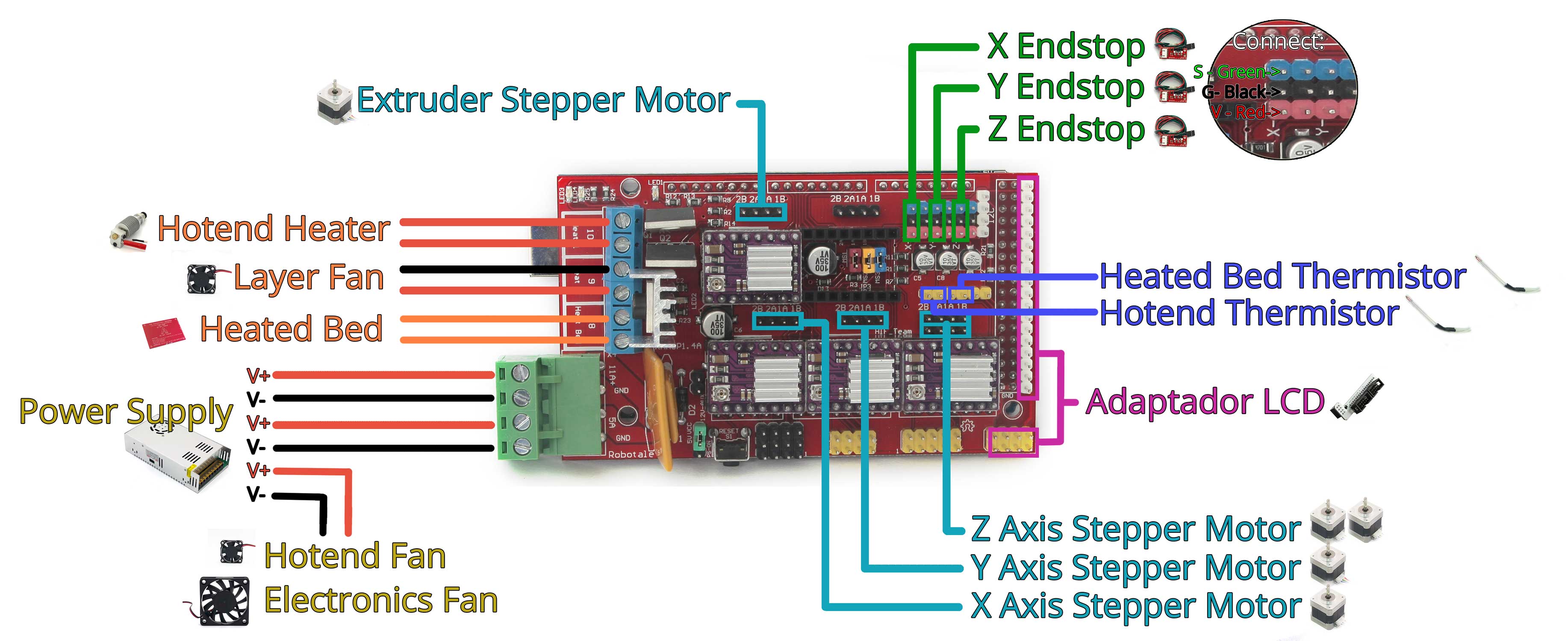
Plug in the stepper motors. for the LowRider, the second Y motor is connected to the Extruder 0 pins. The second Z motor is connected to Extruder 1 pins.
Adjust the vref voltage. The suggested starting voltage is 0.7V. I’m guessing most people leave the voltage at 0.7V, but you can adjust it up in increments of 0.05 if you feel you need more torque. Higher vref voltages will run the stepper drivers hotter, so be careful.
Install the heat sinks on your stepper drivers.
Test your system by moving the axes. You can use the display to move, or you can move using the interface on the manual tab of Repetier-Hoist. If moving using the display, avoid any homing commands. Use Motion/Move Axis/Move X Axis to move the X Axis. If a motor moves the wrong way, you can flip any plug at any connection for that motor.
OPTIONAL
If you plan to transition to the TB6600 drivers, then you will need to learn how to compile and upload the firmware. You don’t need to at this point, but if you want to, here is a page describing how it is done. Also if you plan to transition to the TB6600, you can start by just doing the single X motor and leaving the other four to use the DRV8825 drivers.
@robertbu Once again, thank you very much for your time! I received the drivers this morning! You write: "Upload the firmware to your board. I’m going to assume you are going to do dual endstop wiring. This does not mean you have to have endstops. It just means that each motor is individually wired to a stepper driver. "… Having read the idea of @Atom I think I will try to use a syringe driven by a stepper motor as my project at the start will be to paint works inspired by the aborigines of Australia which involves painting point by point. But Lowrider already uses 5 stepper motors and if I want to add one for the syringe I would not have room to connect it I think? I know I ask a lot of questions … A question that may seem silly: to install the firmware should I connect only to USB or connect to USB and power the card? If I can get my machine to work … it will be thanks to you and all the helpers on this forum!
@Hiram You are Correct, to do the duel endstop wiring and an extruder you would need 6 drivers. I’m no expert on the ramps 1.4 board but you may be able to utilize a fan port and one of your TB6600 drivers to add the additional motor that you need. Though it would take a firmware change, but I belive you will need to modify the firmware anyway. If you go with the v1 firmware (probably easiest route) you would need to modify it to use an extruder, but we could help you through that (not meaning to speak for anyone else but I would be willing to help you with that at least. And I think others would as well)
Edit: though I would still recommend using the default firmware and get the machine working first. Once you have it able to do plotting (drawing with a pen as described in the instructions) then move on to adding the additional functionality of paint extruding. And hopefully @jeffeb3 or @robertbu know more about the ramps 1.4 board and can confirm that you could add an extra external driver as I mentioned above before you do your wiring.
Really doubtful. These drivers still need precise control through step, dir, enable. You could control a DC (brushed) motor directly with the fan port (That’s what a fan is). You would not get great control. But maybe the important thing is to just make sure enough paint is there and the tolerances are pretty high.
To use a 6th driver as an extruder… From the electronics perspective, the skr pro board has 6. Or you can wire a 6th driver using some of the 5V digital pins on a ramps. From the Marlin/Firmware perspective, it knows to move a motor when you add an E parameter to a movement command. It has a lot of calculations and checks you would probably want to turn off (by default it won’t extrude under 150C and it uses a few acceleration values to slow down extrusion and retraction). The hardest part is generating the correct gcode. Which you’re already going to find challenging. You would need to do something like this for each dot:
G1 X10 Y20 F600; to move to 10,20 at 10mm/s
G1 Z-1 E1 F300 ; to move down to -1 and "extrude" one "unit" of paint at 5mm/s
G1 Z10 ; Move back up to the clearance plane.
You’d either need to configure relative extrusion or keep track of how much extrusion you’ve done so far (E1, E2, E3). All these can accept floating point numbers (E1.1 E1.2, etc.).
I think I’m convincing myself that the majority of this project is going to be in the CAM software, and the machine will obey pretty well. The other part that would be very hard (for me) is making the tool bit, where it can hold a brush, and not drip, and have the paint be extruded from a paint bucket somewhere…
Here is a question that I’ve been thinking about. Do you need to chanage colors, or can you do all the blue in one go, and then do all the red and then do all the yellow? It would make it 2x-10x simpler if you can just start the blue job, go work on something else, then come back in 30 mins and swap it out or clean it up in preparation for doing the yellow job.
But Lowrider already uses 5 stepper motors and if I want to add one for the syringe I would not have room to connect it I think?
Yes, you would use up all of your stepper drivers if you use dual endstop wiring. But if you need to free up a stepper driver at some future date, it is easy to go to serial wiring. At the cost of a bit longer wiring runs, serial wiring can all be done at the control board, so you don’t even have re-run the wiring in the machine. I suggesting you use dual endstop wiring to start since it is simpler for you. If you decide to go serial wiring instead, you would need to wire up a serial harness. You can find a diagram on this page. And V1CNC_Ramps-2.0.7.2-src.zip is the serial version of the firmware.
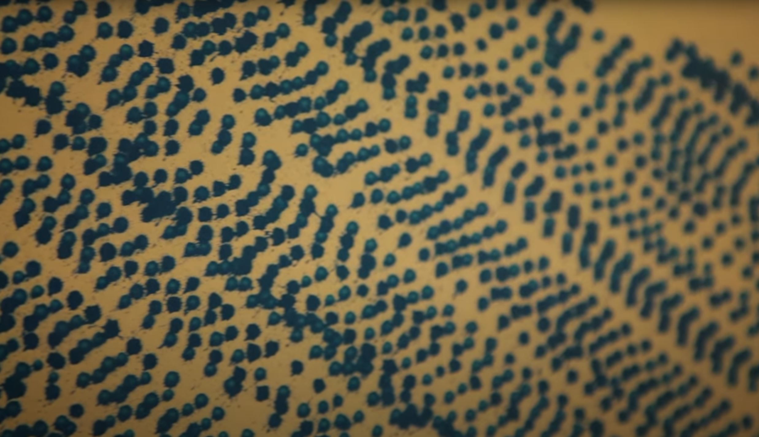
I’m not convinced that the syringe to apply paint is going to be your ultimate solution. Don’t get me wrong, I think Atom’s idea is great one to test, but there are lots of other possibilities. Things like a foam brush fed by gravity from a reservoir, or spray paint. This video came up on my YouTube feed the other day, and I though, hey there are the paint daubs that Hiram wants to paint. His system is far more complex than you need, but at a distance, spray paint makes nice daubs. If/when you decide to test a syringe, you can physically push the syringe to test things out before you have to free a stepper.
If it were me doing this project, the first thing I would do would be to design a magnetic brush holder. I would output the CAM so that the machine paints 10 dots and then brings the brush back to be to change for another paint-filled brush. I would be the the part of the machine that refills the brush. This is not how you ultimately want things to work, but you would learn a huge amount about how to get a CNC to apply paint with this simple step.
to install the firmware should I connect only to USB or connect to USB and power the card? If I can get my machine to work … it will be thanks to you and all the helpers on this forum!
You only need to connect the USB in order to flash the Ramps boards. Note that is not true of some other boards. In fact, you can flash Mega board before you even connect the Ramps board to the Mega board.
Getting the firmware installed is a great step. Assuming your machine is built, you are very close to having it move. Setting the vref is the only other major work item, and that is easy once you figure it out.
These are not stains, these are points that I would like to do
I think there is something lost in translation since “stains” does not really fit. After you first mentioned “paintings of Australian Aborigines,” I googled some images. It is a beautiful style.
Edit: If by stains, you refer to spray paint, then what I was writing about is shown in this screen shot from the video I referenced:
Their spray method produces dots/daubs. It does show artifacts of the spray process, but it might be a good way to produce art that is “inspired by” Aborigines. It all depends on your goals.
Just a thought but maybe start with markers/sharpies there are plenty of pen holders available and it will give you an easy milestone on your journey to your final build. You could use the same Gcode to draw your dots basically a million shallow drill holes with a few tool changes.
If your painting on a flat medium you may be able to design an endstop switch on Z min that drips/sprays when triggered.
Thanks everyone! I will remain modest and aware of my limits! I finish the wiring with the precise instructions of @robertbu and then I think about what to do next … If the machine moves … it will already be a great joy!
It is beyond my electronic skills to evaluate what could go wrong with this combination. I think it is okay as long as your power supply and regulator supply enough amperage. Your regulator needs to supply at least 5A at 12V, and I’d feel more comfortable if it supplied 6A or 7A since power supplies can be overrated. Assuming your regulator is switching with some decent efficiency, then you will need 3A to 4A of 24V power to your regulator. Based on a bit of reading, what I would not do is feed the Ramps more than 12V. The Ramps board itself will handle it, but according to one manual, the Mega does not do well with higher voltages:
The recommended power supply for Ramps is 12V, especially for Mega2560. If supplied over 12V, mega will overheat, resulting in instability of operation…
Maybe someone with more electronics training on this forum can confirm my assessment here.
I believe you are okay with this this setup if your regulator will output at least 6A and your 24V power supply will output at least 4A. If you have a converter like the one pictured at your link, typically they handle at least 10A. Personally, I’d find a 7A 12V power supply just to simplify things and have one less things go wrong, but I understand that the relative price of things and the parts availability is very different in other parts of the world, plus wanting to make use of the parts you already have.
People on this forum with far greater electronics knowledge that I have suggest 0.7v to start and then stepping it up by 0.05V at a time if needed. They suggest that higher vref voltages, thought supported, will run the drivers hot and you might risk a shutdown of a driver in the middle of job.
Edit: Did a bit of reading. It is suggested to not run your steppers at their max, but instead set them for 85% to 90% of max. So the equation becomes (1.7 * .0.85) / 2 = .0.72v so that is likely 0.7v is the suggested starting point for vref.
That 0.7V comes as a rule of thumb. It is funny, but for all the stepper motors and all the driver types, 0.7V is pretty close on most builds.
If it is too low, you will lose steps (it doesn’t hurt anything, but it can ruin a job). If it is too high, either the drivers can overheat (and they will shut down until they cool off, like a minute, ruining a job) or the motors will overheat (try to keep them below 50C) and they can make the motor mounts soft enough to bend, especially in hot environments.
@jeffeb3@robertbu I suppose you understand that for a novice, the equations which one finds on the net and which give different values are quite scary … I will obviously try with the 0.7 volts that Robert suggests … when Robert told me to search the net to sort out Vref I didn’t expect to find so many theories. So I try with 0.7 tomorrow if I find a voltmeter on loan … But I still do not understand “increase 0.05V at a time if necessary”. I don’t know if I’m an idiot but what makes “necessary” then? Guess the engines are behaving badly? I am learning a lot with you! In response to Robert: I use the material I bought to the maximum to try to build a CNC machine before giving up for reasons of incompetence …
It’s tricky to describe. You will be able to overpower it regardless of what it is set to. But you don’t want it to slip when milling. I would start with 0.7V and basically just forget about it until you start milling. At that point, measure the temperature of the motors. If they are significantly less than 50C, and you want the machine to be a little stronger, you can give it a bump.
It can be tempting to make it “as strong as possible”. Or to want it to be completely impossible for it to skip steps. But it isn’t really necessary.
