I personally have no issues with using zip ties. I think the main focus should be trying to get the footprint of this as small as possible. if that means using zip ties do it, if someone has a issue with it maybe it will push them to come up with an ingenious solution that could be implemented into the next version.
1 Like
The belt terminates on the center block. So the smaller I make this block, I think the more room there will be to tuck in a board.
The trucks-rollers-corners pretty much dictate the outer size and the trucks-center block dictate the usable area. Like it is now though we have that area (corexy) that is the non-rail edge, that can give room to tuck in a small board for minimal designs. This is what I am thinking about and I might be overthinking it. I will have another look to see what I can do.
For non minimal builds I think there is plenty of room to stash a board so we’ll see. Zip ties are inexpensive, easy, and have the smallest footprint. Not a big deal if we only needed one screw but we have the tension equalizer pass through to constrain as well. I hope to get a chance to work on this again this evening.
1 Like
Chiming in a little late… No idea how I missed this topic for so long.
Zip ties are fine for what they are. I’m a fan of inexpensive and simple.
I’ve done things where I thread into plastic. I’m more than willing to run a thread tap through a hole. I’ve used printed plastic nuts for things, and as long as the load is reasonable, they haven’t been a problem. A little rubber cement makes them not bad locknuts even.
The design parameters that you have listed seem good to me. I’ve stated before that I’m a big fan of open source. I sometimes like to tinker with things in ways that the original might not be intended for. I’m also one of those “speed demons” that you refer to. I know that my build of the ZenXY introduced some issues, due to the speed that I was running the table.
To your stated goals:
- Work area: I had some extra left over. I’ll be doing a new one once this build is complete, so even if the work area were slightly reduced, I’d be fine with it.
- Unique part count: The part count was so minimal with the ZenXY, I probably don’t care.
-
Fully Constrained Rails: I’m a fan of this idea, see speed demon comment.


-
Mechanically Quieter: Honestly, I didn’t have a problem with it. I did use a set of motor vibration dampners, but even with the DRV8825 drivers on a RAMPS board, it was quiet enough to leave running while in Zoom meetings

- Same Magnet: Finding one was a big headache for me. Not having to find a different one would be nice. (Actually, I’m using a stack of 1/8" thick discs heat-shrinked together.)
- 10mm belt: I’ll probably stick to 6, but I can manage those differences myself.
- 2 sizes rails: Actually OK with this. Before, having the 1" tube was a plus, because I had it left over from building the Primo. I’d have to buy the conduit, but no big deal.
- No Endstops: Given my current frustration, (see below) sounds like a plan, but the endstops themselves were never really a problem. I’d probably be happier if they didn’t rely on the belt not twisting with the endstop though. Maybe 10mm belt makes this easier…
As to the idea of sensorless homing… My ZenXY is currently out of commission since it started trying to eat the X limit switch. Something in the belt holder moved, and the block gets caught in the lever arm of the switch and pops it out of the switch body. I haven’t had time to diagnose it. I replaced the switch and it just happened again right away, but I was able to observe it. Still, I think that it would be in keeping with the overall plan to provide for limit switches if that’s how people want to run. Some people like me might want to just rebuild and keep their current electronic packages.
Okay, back to the Open Source idea. I’m sure that it could be done. In implementation, it’s not terribly different from the rest of your stuff, particularly if you don’t mind us just printing/building our own without buying, only that actual CAD files would be available, not just finished STL files for the printed stuff. As for pitfalls, the biggest one that I see is that if you offer ONE project as open source, you may get some people (And I use that term loosely) demanding that you make ALL of your projects open source. Well, maybe MORE people. We know they’re out there already.
Profitability? I’m never sure how profitable any open source project is, but I know plenty pf people will pay to have less work to do. Hardware kits, printed pieces, and the like sell reasonably well, and plenty of people who could do it themselves will pay for it because they want to support the project. Some of the harder to find pieces you might be able to get a deal on in bulk. For me, buying one magnet, the shipping cost was prohibitive, which resulted in a non-optimal solution being used instead. My solution works fine, but certainly isn’t the best one by a long shot. Make the “one-off” hard to find pieces part of a kit, and it makes it much more appealing to buy. Your current model would probably retain the same profitability open or closed source.
Tough as it is for me to say, I believe keeping the same closed source concept is likely to be your best fit. I’d like to be able to build without buying plans or STLs, but I’d be open to reasonable prices.
3 Likes
This exact thing in the exact same place happened to me. Little black switches with a red roller?
Mine have a white roller, but they’re the same switches, I’m sure. I have ones with red rollers, too.
Drifting off topic, but I think what I’ll do as a solution is print a big plunger for the switch so that the block can’t get behind it. Or just put a big blob of hot glue on it.
Oh, and I’m sure that it’s way too late to chime in on design ideas… But the one that I’ve been tinkering with, I run the belts inside the tube for the long run. This keeps it out of the way, where my ZenXY was sometimes chattering pinching the belt between the rollers and the tube.
Belts are inside the outer rails! Great minds…!
I had to do that to save space. This one is so tight for the first time I am designing with mostly transparent outer surfaces to be able to make sure things have enough clearance. Makes it exciting.
Out of curiosity what is the min hight needed for the whole mechanism?
So far without counting the steppers, 65mm. The steppers are mounted the other way so pancakes can keep it short (I hope, or larger ones can be used). I am trying to keep it thin as possible.
Lets not get to carried away with DIMs yet, This is not done and not even tested. I have been banging my head against the desk with this belt tensioner/clamp. I think I am close.
1 Like
Pancakes are one solution. The other is to recess the motors into the table surface. This should be possible, since the table needs some depth anyway to have room for the sand/baking soda and the ball. I had parts pocketed into my Ikea LACK table design anyway.
I’m really looking forward to this design. I already bought a new Ikea coffee table, and I still have an extra glass shelf, since the one I bought came in a package of 2. Looking forward to a BOM so that I can get started on a build right away. I might cut the opening for the glass in the table top before the design is ready. I’m going to try a slightly different approach to the inside, and round the inside corners. I sometimes get baking soda packed into the corners as it is now, because of course the ball is round. If I 3D print corner pieces, then set in the sides, I can make sure that the corners cannot trap sand in them. Similarly, I can bevel the edges of the bottom in order to deter build-up.
I haven’t decided on lighting yet. Some nice indirect lighting would be good. I actually didn’t miss is as much as I thought I might with my current table, but it’s not like I can’t switch the lights off.
The other way, out the bottom. That uses one reference plane…or I guess they could go up. I will need to think about that.
I do really want lights in the next one, it looks great.
Rough rough rough. I have a screw tensioner now. Finished it after this screen grab.
Oh boy I just had a really nice idea and reduced the unique part count even lower!
1 Like
The motors going upwards works for me. I can see where it might not work for other people though. The advantage that I have is that I only have to worry about making exactly one person happy with my result, and I can plan it based on a specific table.
I’m practically certain that I’m going to build the next version of this, so I’m glad to hear about good ideas. 
3 Likes
I might be too… I want to see if I can fit two small zenxy into a kotatsu I have been meaning to build for a few years now.
Maybe a dumb question but why do the motors have to go in the corners at all?
What stops us from putting the motors in the middle like this:
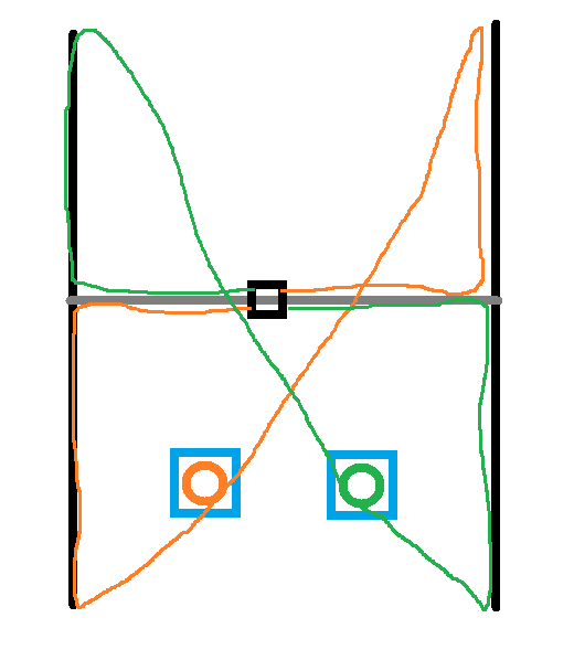
I’m thinking CoreXY in traditional applications needs to keep the center area clear. For example a 3D printer with motors (and crossing belts) sitting in the interior of the volume above the print head will collide with the filament that extends above the print head. But for ZenXY there is no such restriction.
1 Like
I thought the motors where mounted on the outside edges because you want your entire belt to run in the same plain and if they where in the interior the gantry would collide with the pulleys.
Otherwise you could mount them in the middle(as you show it) above the gantry on any 3d printer right?
The only restrictions I know of is any variable length section has to be parallel to the axis of motion. Other than that you can move any fixed point or even add more fixed points. There are several printers with the steppers out of line 90 degrees to let you tension them.
As for why not put the Zen steppers there, it would increase the depth. The carriage has to pass over them so you would have stepper height+ carriage height. Currently we have the steppers offset ~30mm up at least.
1 Like
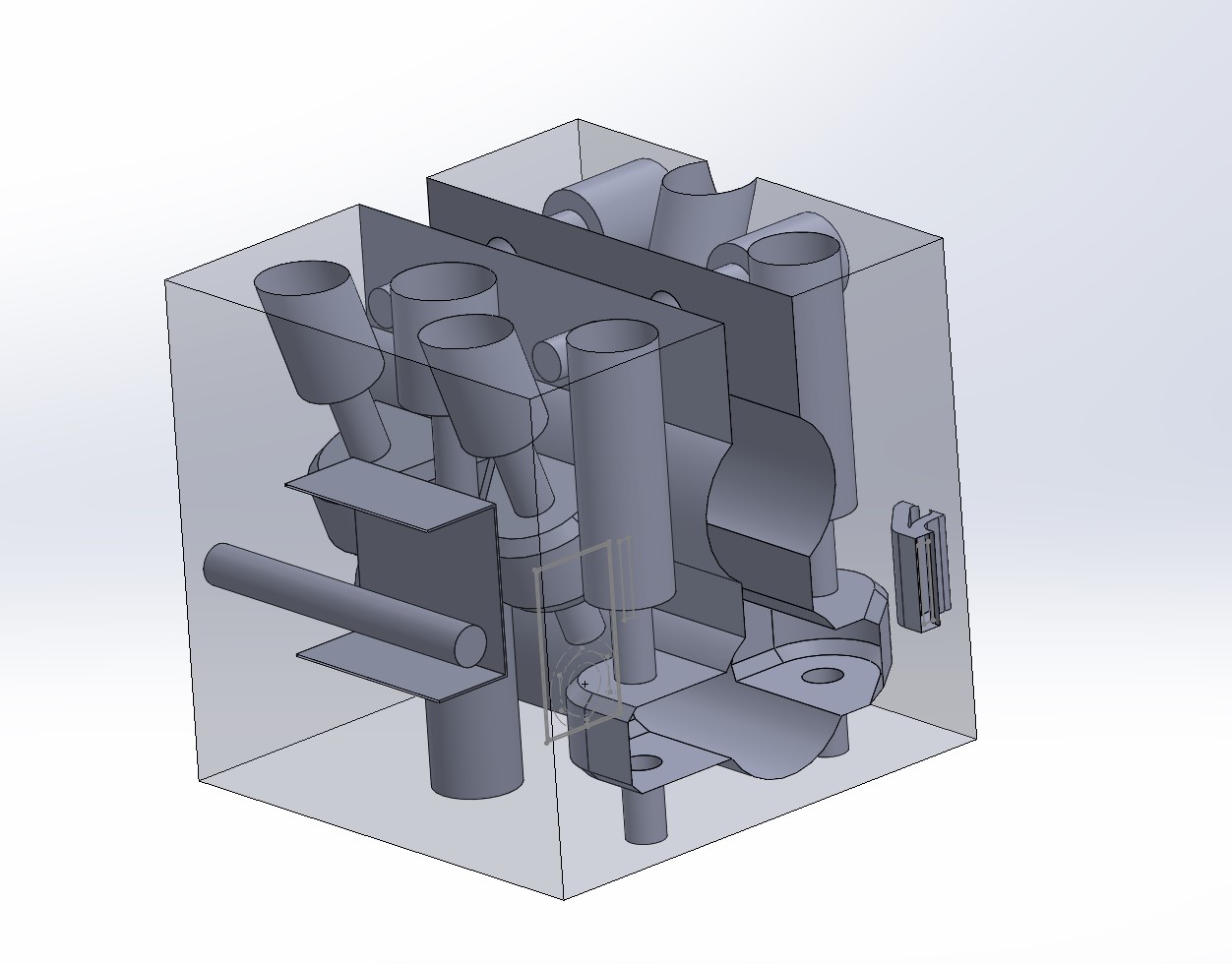
So the only challenge I have right now is anchoring the equalizer section of the belt, the part that lets you set the tension then pinch it against the carriage. The tensioner works, needs a tiny tweak but it is good. I printed two different non zip tie loose end holders and they both work…kinda fiddly so the only complaining I want to hear is “geee gosh Ryan those zipties sure were easier”…
4 Likes
Okay…I am really close now. I just need to work out the belted corners. The trucks, center and motor corners are final (at least as far as I can tell). The parts are easy but fitting it all together to work in the same space as the last one is taking some very careful CAD. I think I made it but fingers crossed I get to put the first full proto together tonight and run it.
Gunna need some beta testers soon I hope.
4 Likes
Willing to beta!
Looking forward to seeing the design!
1 Like