NeXtY PLOG, Zen Mk2


So my 3D printer has been busy again.

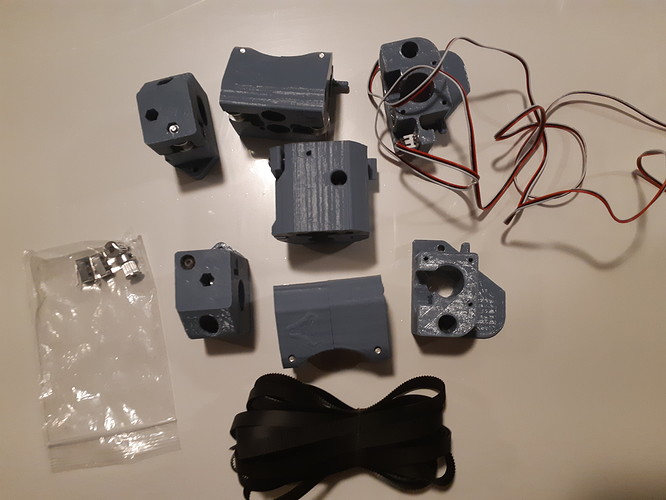
Just starting out, this table is intended as a gift. These are the new Zen XY parts, the release candidates. The pulleys and POM wheels are already included.

I intend at this point to enclose the mechanism, since the intended recipient has young children, and I dont want little fingers getting pinched by moving belts or the trucks. It was a hard decision to make because the parts are beautiful, but safety wins the argument, I think.

I plan on making the operational parameters the same as my table, so that I can share pattern files between builds.

1 Like

Okay, So I’m doing up the CAD for the table.

This is going to be based on my UTRUSTA Ikea glass, and it’s set up to be just the right size around it for the table top. (I think I gave myself 1mm extra.)

The short and long ends will be set up so that the long ends (13mm thick) will overlap the short ends. These will be made of solid wood with the grain upright. (Short Ends.dxf Long Ends.dxf)

The top will be a laminate. Two layers for the bottom. (Lowest Top.dxf) One will be 1/4" MDF with a pocket cut to bring the thickness between the magnet and the baking soda down to 3mm or less. Another layer over that will be the same DXF, but 3/4" MDF with the pocket hole cut completely through. The layer over that will be 1/2" MDF (Light Layer.dxf) which has the hole enlarged by 15mm all around which will have a recessed LED strip light. I’m soldering up a PWM dimmer circuit for that now. It has an access pocket through to an opening in the lower layers for power. An then there’s the table top surface itself. (Top Surface.dxf) This will be another solid wood layer. The MDF layers will be painted white where visible, particularly inside the recessed area for the lighting, hopefully the bottom won’t matter much.

Underneath the mechanism I’ll put in a floor for the electronics, power supply and sth. The Short Ends.dxf file has openings for the power entry and switch, but I think I’m going to put all those out the bottom to sort of hide it all. I’ll leave a little trap door in there to get access to the Pi and electronics, in case those need maintenance too. I didn’t do up any CAD for that yet, since I haven’t decided which board I’m using.

The CAM for the top surface is giving me a headache. I wanted to have EstlCAM cut the hole through the top surface all the way leaving rounded corners, which would end up holding the glass shelf, then notch out the corners so that the glass sits flush, but EstlCAM doesn’t want to follow the rounded corners. If I choose manual selection, I can make it cut the corners for the path where it cuts through, but it does so in straight lines, which wasn’t what I wanted.

Well, for cost consideration, I might end up doing the solid wood layer for the top from boards, ripped to the appropriate width, and do some joinery in the corners. Might not look quite as fancy, but will use less material.

Zen Laminate.zip (7.4 KB)
1 Like

Realized that I made some errors in the CAD on that drawing, plus some things that I didn’t like nearly as much. Well, this is an excercise in teaching myself how to do stuff like this, so… Back to the (virtual) drawing board.

I assembled a dimming circuit for the LED strip, but it doesn’t work. It’s a pretty simple 555 oscillator to manage PWM dimming that I soldered up on breadboard, but something doesn’t like it, and it seems to be stuck at 50% PWM all the time. Well, I kind of bought junk stuff for this, because I didn’t have enough to buy to get free shipping from Digikey. The lesson remains the same. The cost of cheap parts is the cost of the cheap parts plus the cost of the “expensive” parts to replace them.

The breadboard is actually kind of a bother, because it ends up needing jumper wires all over the place. This may be the time to try milling a circuit board. Put one of my 0.6mm router bits in and give it a whirl. (This was supposed to be the job for my 3018 that broke during testing. I should rebuild that…)

Still plugging away…

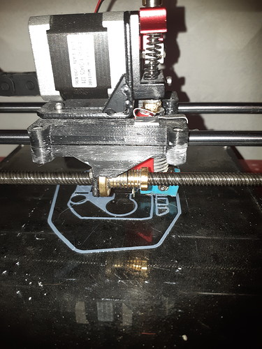
Guess what this test is…

4 Likes

Soda crown!

1 Like

RC? :stuck_out_tongue_winking_eye:

1 Like

I’m a bit late to this party, but if you’re just powering LED strips and want to set brightness to a specific level, then leave it alone, you can get cheap DC-DC buck converters that allow you to set the output voltage. I use a pair of buck converters in my table that take the 24V that powers the controller and motors and drops it to about 12V for the LEDs (red and blue). I adjust each output voltage to try to match the visual brightness of the two colors. The buck converters are about 95% efficient so they barely get warm in operation. \

I use 5050 type LED strips with 60 LEDs per meter. Running the LED strips at the rated 12V makes them pretty bright, so I keep the voltages set a bit lower than that. I also mount the strips on a piece of aluminum L stock to act as a heatsink. It warms up a little in operation, but I can touch it comfortably so the LEDs should last a long time.

I guess it’s been a while since I’ve updated this topic.

The table is done and delivered, but I forgot to take pictures. Maybe when I can go visit, hopefully soon.

I wanted the light levels to be adjustable from full brightness to off for varying light conditions in the room. The knob for the PWM dimmer is next to the power switch, hidden, but easily reachable. The LED strip is stuck to an intermediate layer of the table. They do warm up, but don’t get hot. I’m using the same LED strips for under-cabinet lighting in the kitchen, just stuck to the cabinet. I think they’ll be fine, and they’re not super difficult to swap out if not.