Finally made my first cut with my LR2 using a V Bit and it went great.
I have been so cautious with all the cables not dragging: using the Hackaday measuring tape solution; hanging the router cable from a shock chord attached to a hook in the ceiling; etc. All working great.
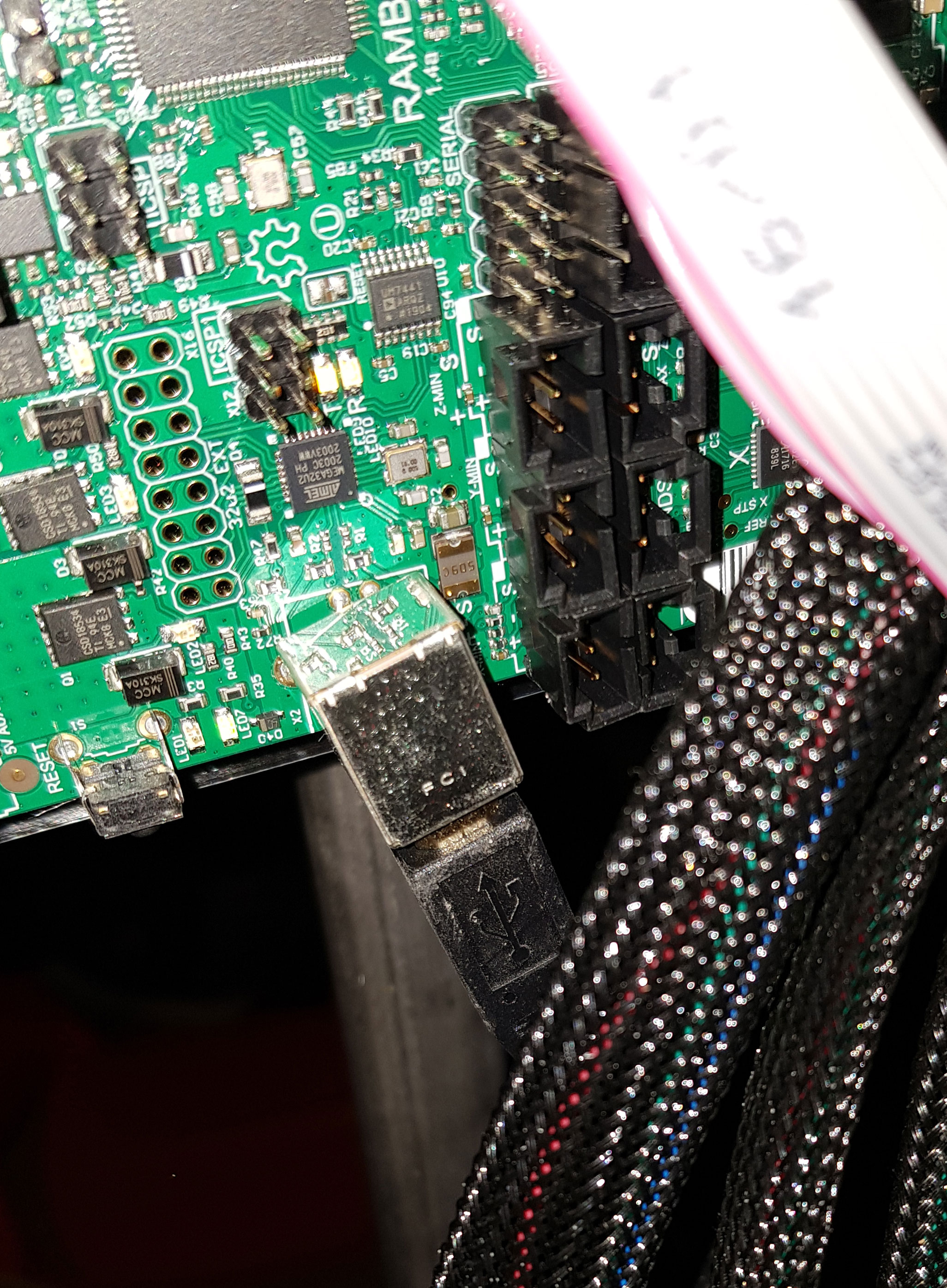
Then was moving the gantry along the Y and whilst concentrating on that hadn’t noticed the USB cable (between Rambo board and laptop) had been pulled taught and had put too much stress on the USB terminal on the board. It is now seriously loose/wobbly and is out of straight. What a schoolboy error!
That’ll be a weak point now, so I have some questions that I would be very grateful for advice on:
Is this something that a computer tech guy would find easy to install/solder on a new one?
Is this a simple fix that even a total newbie could remove and solder on a new one (this newbie has zero experience in soldering! But there’s always a first for everything, and love to learn!)
I would like to stay away from having to use Repetier Host and a USB connection between the LR2 and a laptop. Although I know there are less options when running off the SD card, do any of you guys use the SD option instead?
If I go the SD route, which is the best way to add gcode such as the much needed “G92 X0 Y0 Z0” to a file that comes out of ESTLcam. So far I have had to add that code manually in Repetier Host.
I run my MPCNC off an SD card. My biggest frustration was navigating electronically. It is cumbersome from the LCD interface. I ended up adding a pendent to simplify the process. There is also provisions in later versions of the Marlin firmware for directly connecting a joystick.
If I go the SD route, which is the best way to add gcode such as the much needed “G92 X0 Y0 Z0” to a file that comes out of ESTLcam. So far I have had to add that code manually in Repetier Host.
In Estlcam, go to Setup->CNC Programs->Texts->Program start. You can add g-code here that will appear at the beginning of the .gcode file output by Estlcam.
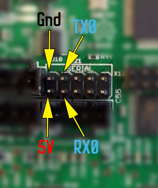
But the problem solver in me knows that the usb is just a uart converter. You could connect a usb ftdi to the rx0 and tx0 pins and basically replace the usb port.
Yeah, using the serial connexion is a good fix.
But to be honest, replacing the usb connector isn’t that difficult either. For sure it cannot be done by someone having no soldering experience at all, but after a bit of practice it is really not that hard.
So maybe it’s a good opportunity to learn a new (and very, very useful) skill!
You’d need a basic soldering iron and a small desoldering pump, both of these tools are very cheap, just a few bucks.
Does it still work ok? You might be able to goop it up with some hot glue and add some extra strain relief to the usb cord and use it for quite some time. It would make further repairs more difficult though.
I’ve never had the full sized rambo, but from my experience and from the picture, it looks like there are through hole pins for stability, but the data and power are coming out on the surface. But even with through hole, you can rip the pads off. I’ve done it a few times.
Hi,
Sorry to sound vacant but when you say ‘rip the pads off’ what does that mean? Dealing with board components is a totally new step for - a step I am enjoying but clueless about.
Thanks
The solder pads are the part on the PCB that the USB port solders to. They are thin, and on the surface, and can be pulled off. At that point, getting it soldered back in place won’t fix the connection from the pad to the rest of the PCB.
I am a bit worried to use the USB connection now, as although it is still functional, it’s a weak point due to my silly error.
So I can use an SD, as I use the same method for my printer. However, as I progress with learning this awesome machine, I imagine I will want to have more flexibility whilst using it.
Would you say the OctoPi option is a good way to do this?
Ok. So if I was to immobilize the usb port with some hot glue, is it ok if the hot glue touches some of the other elements that are right next to it (in a few mm proximity to the port)? Sorry for the silly question!
Do you happen to know if anyone has made an explanation of connecting to the UART pins?
Hot glue is usually insulating. You can take a multimeter and see if it has a ton of resistance. But I would be comfortable using it without testing it. In my day job, we have used hot glue to secure cables in place in big trucks with lots of vibration and it worked well. You can even cut out back out or heat it back up to adjust it.
I know there are guides for parts of the process. But I am not sure there is a complete guide for this in a rambo. If you round the pins to connect on the rambo, the rest should be identical to a ramps.
The way it works is the usb is really just a usb to uart converter. The serial data goes through the board and connects to RX0 and TX0. So if you used the TX and RX pins on the pi and connected to the RX0/TX0 on the rambo, then anything on the pi serial port would go to the rambo, and the rambo would not know it didn’t come from USB.
The pi has a few more tricks though, because it sends diagnostic data over the serial port already. So you need to turn that off. Also, since most people don’t use that port, octoprint has intentionally ignored disabled using that port in octoprint. So it needs to be reenabled.
That all might sound complicated, and it definitely is more complicated than some “hot snot”! But I am sure there is a youtuber like Chris’s basement that explains it in a clear way. There aren’t many steps, and they aren’t complicated, but they all need to be done to get any feedback that it is working.