I am completely new to cnc milling but have some experience with 3d printing.
So I hope someone can give me a step by step guide to what to look for and possibly a solution.
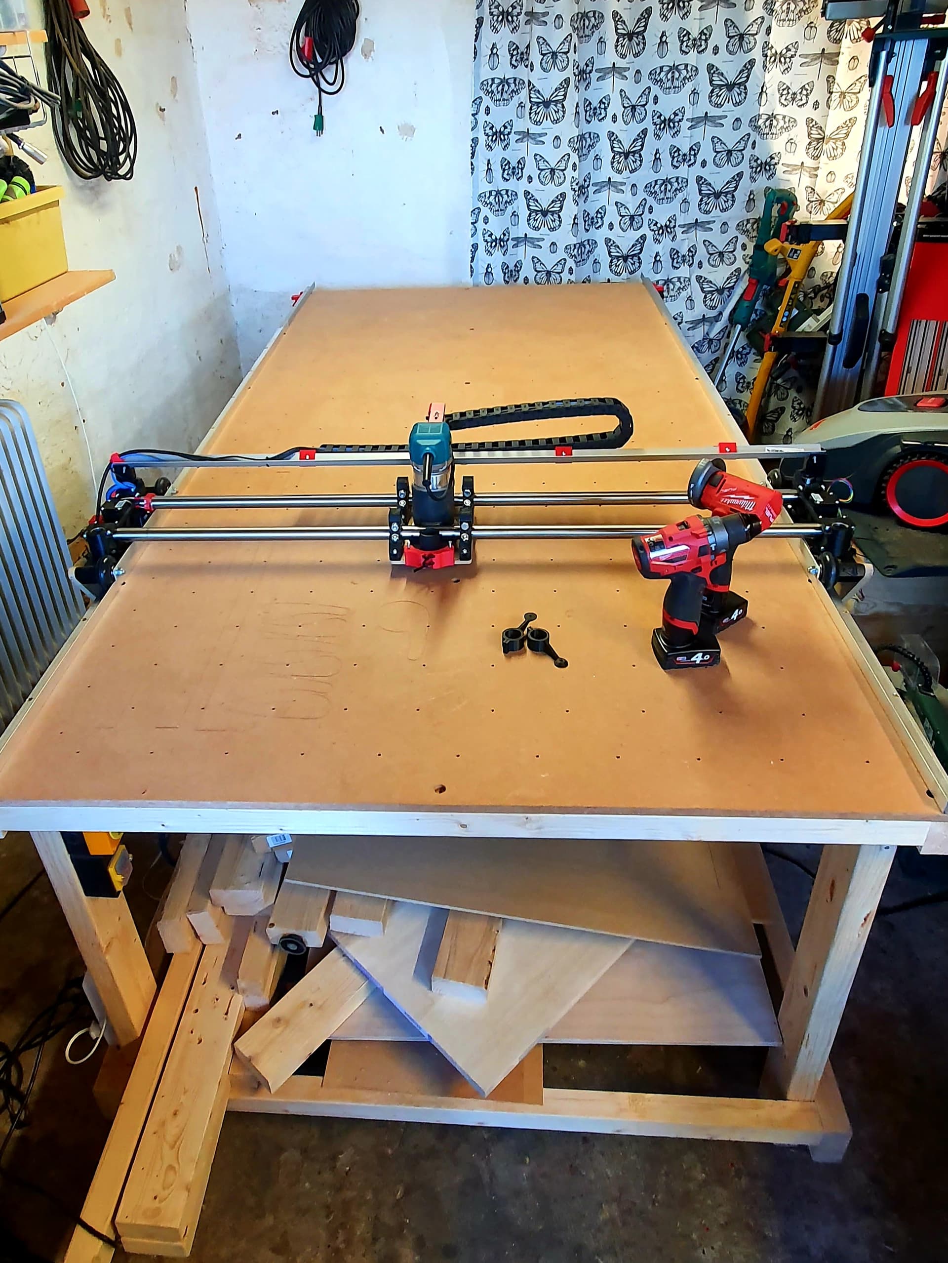
I have a lowrider2 cnc. everything bought here on the site.
Motherboard: RAMBo 1.4 with dual endstops and Z-probe
firmware: dual endstop.
CAM: Vcarve
G-code Sender: CNCjs on windows 10
Post processor: Marlin_mm test 5
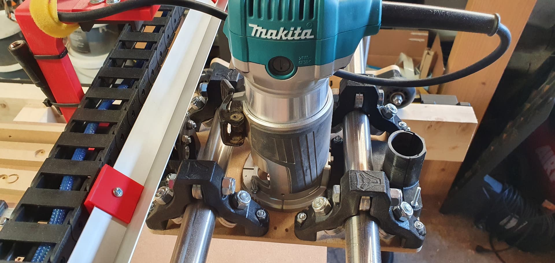
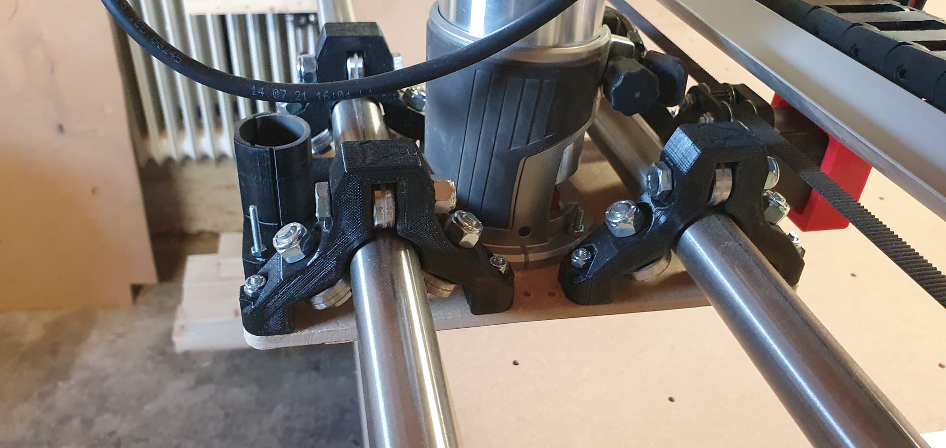
Router: Makita RT0700C.
Bit: Single flute ″1/8 ″, 8mm / s Feed Rate, 3mm / s Plunge Rate, 1mm Depth of Cut, 40% Step Over
Material: plywood
t
I’m making my first cuts for a fence to my spoilboard and some clamps and it’s not going well.
It seems that after a task is finished, the next does not align the previous.
I stopped the job as there was no reason to continue, therefore there is only 1mm profile
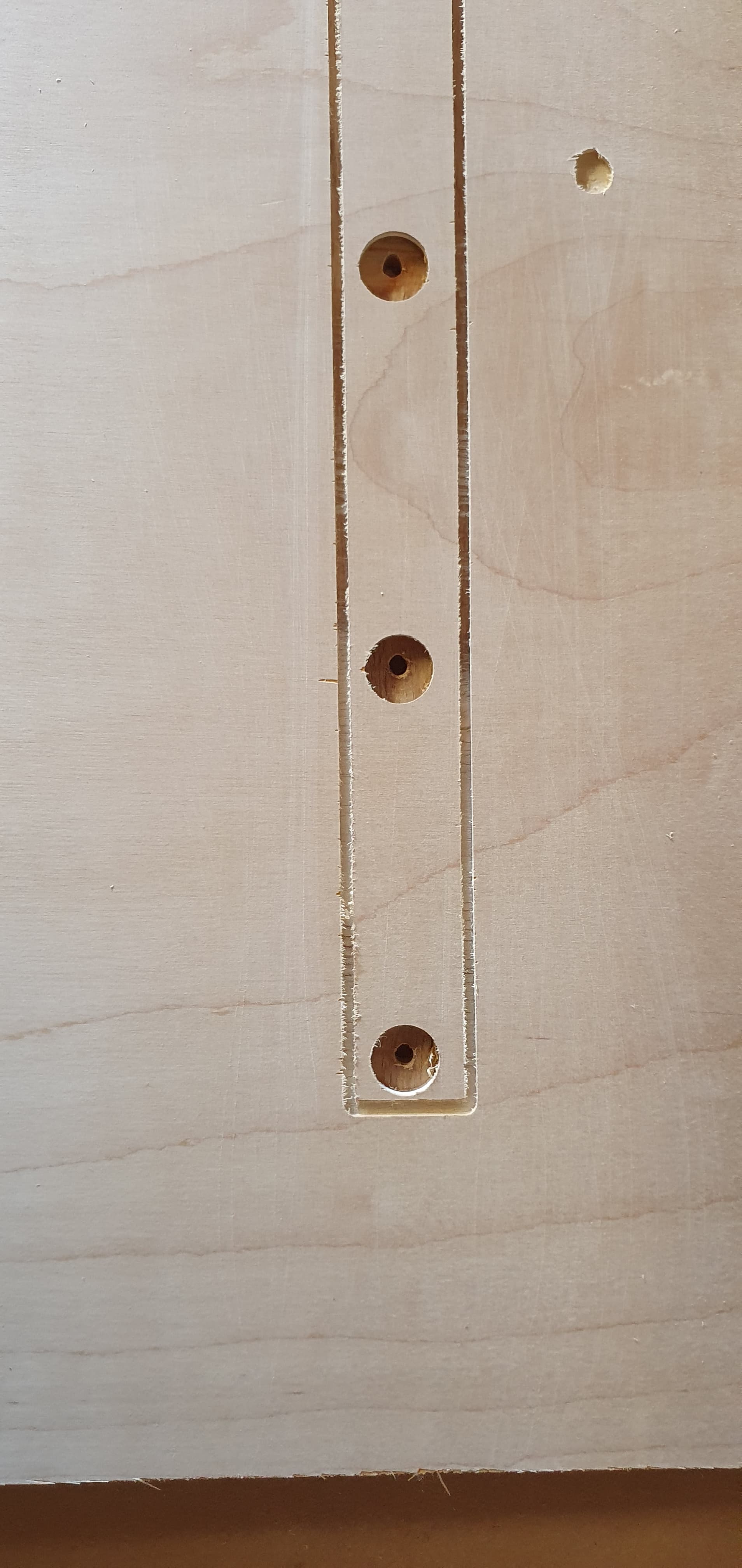
As you can see it is getting worse and worse on the y axis.
First I make a pocket toolpass 4mm deep and then I “drill” the holes also via a pocket toolpass start depth -4mm and depth 8.5mm.
Eventually I run a profile.
All in one gcode file, as I do not have to change the bit.
I have also tried to make a test cuts of a square and it did not measure the same length and width either. about 4mm difference
So something is completely wrong and for what I need it my cnc for is currently useless.
The problem is that I do not know where to start and how to solve it.
That is not good. It can definitely do better than that.
Here are my first thoughts:
1mm DOC is pretty shadow. You’re doing a lot of passes. It should definitely be able to work forever without slipping around, but whatever this issue is, it is worse because you are lining up a bunch of passes, instead of a couple. Try taking the total depth and dividing by 2 or 3 to get in the 4mm DOC range to take fewer passes.
What kind of bit do you have? Drilling is sometimes the hardest thing to do, because there is no where for the chips to go. Especially if you have a downcut or a large number of flutes. I would use a spiral upcut single flute 1/8" for this job. Can you tell from the pictures, did it get off when it was drilling?
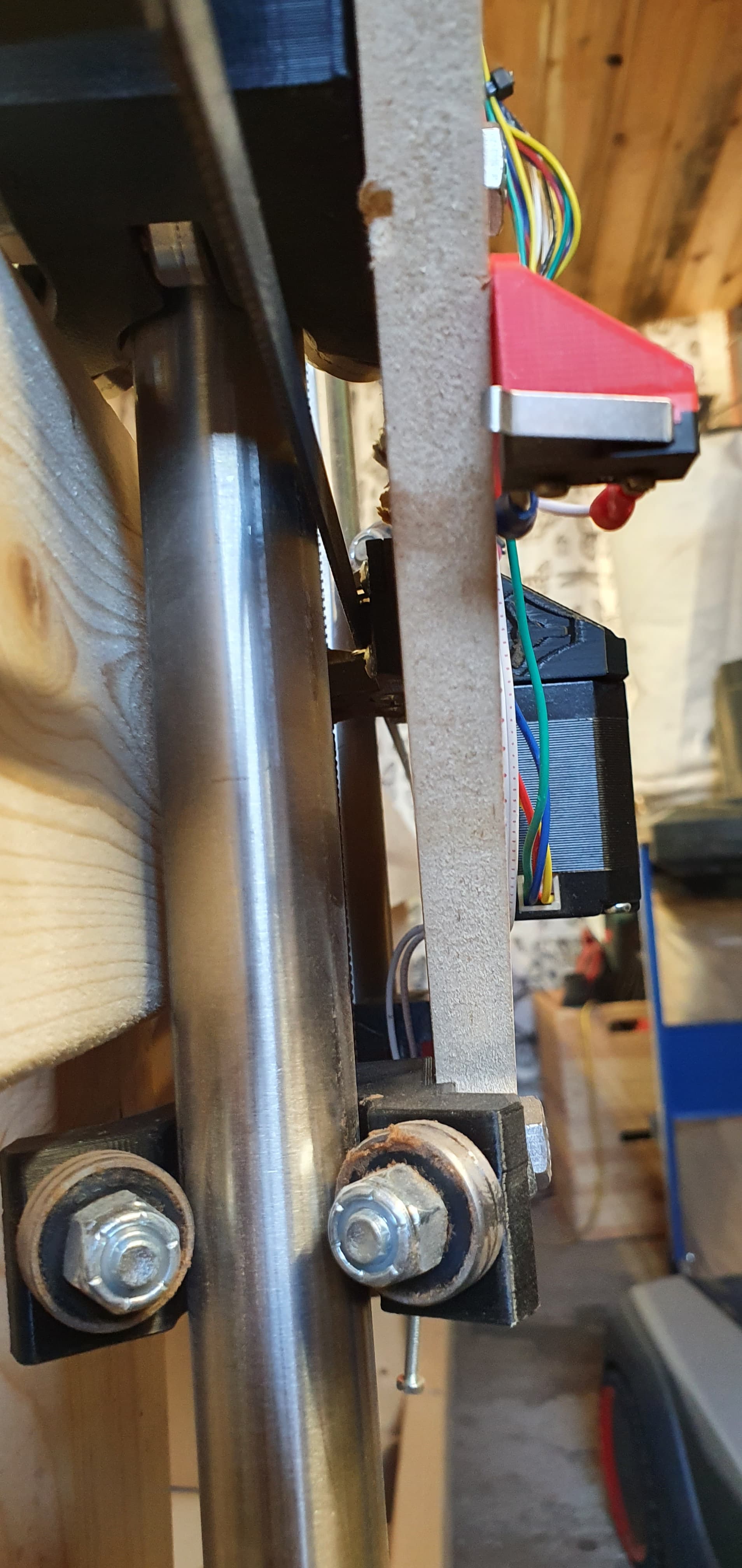
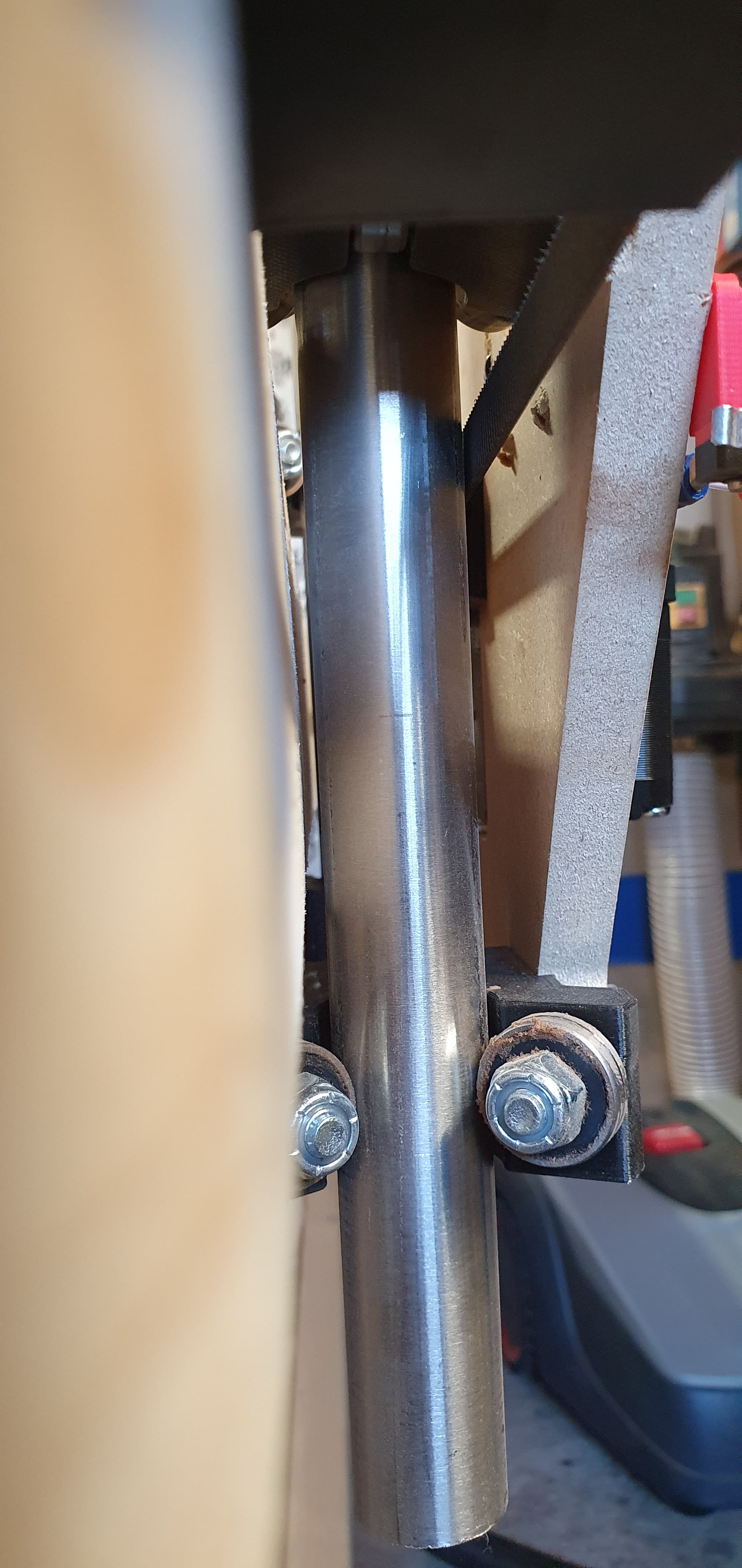
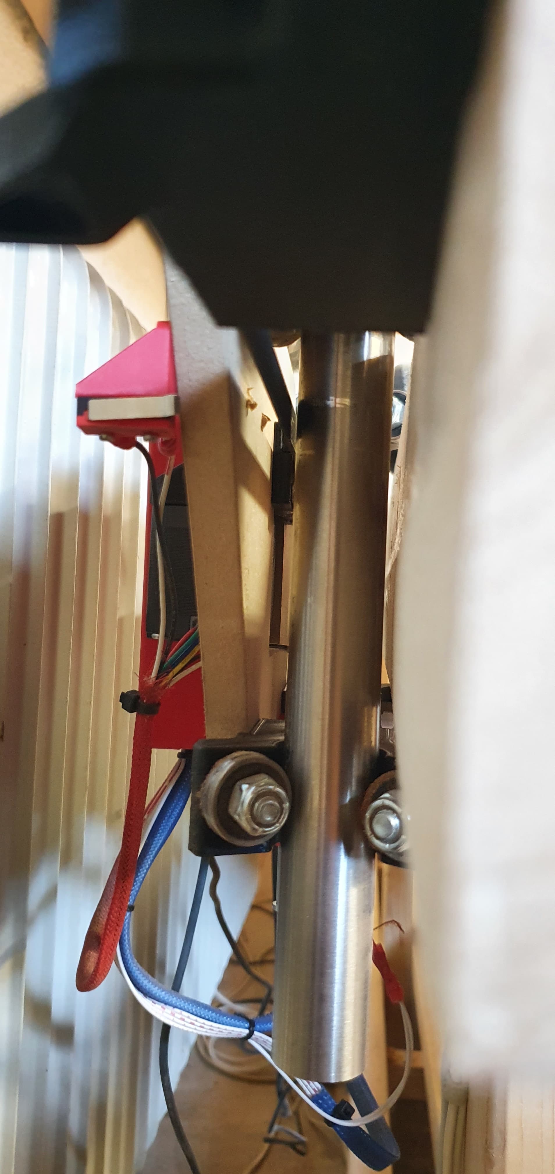
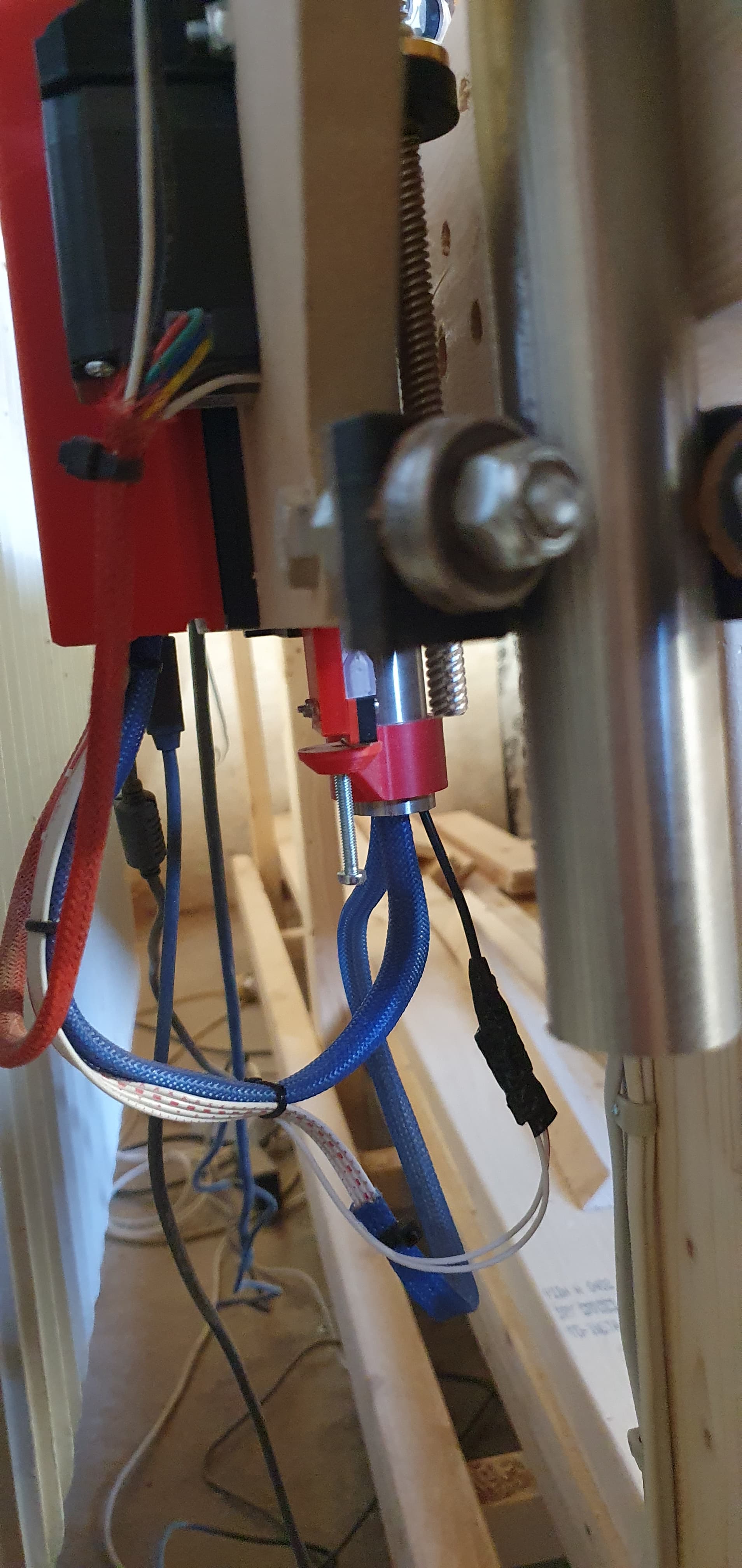
It is slipping in the Y direction? So it is like the wheels moved farther than they should? Not the tubes/gantry X direction? Some machines have trouble keeping the X from sliding to the side, and some mechanical fence for the wheels needs to be added. But that won’t affect Y.
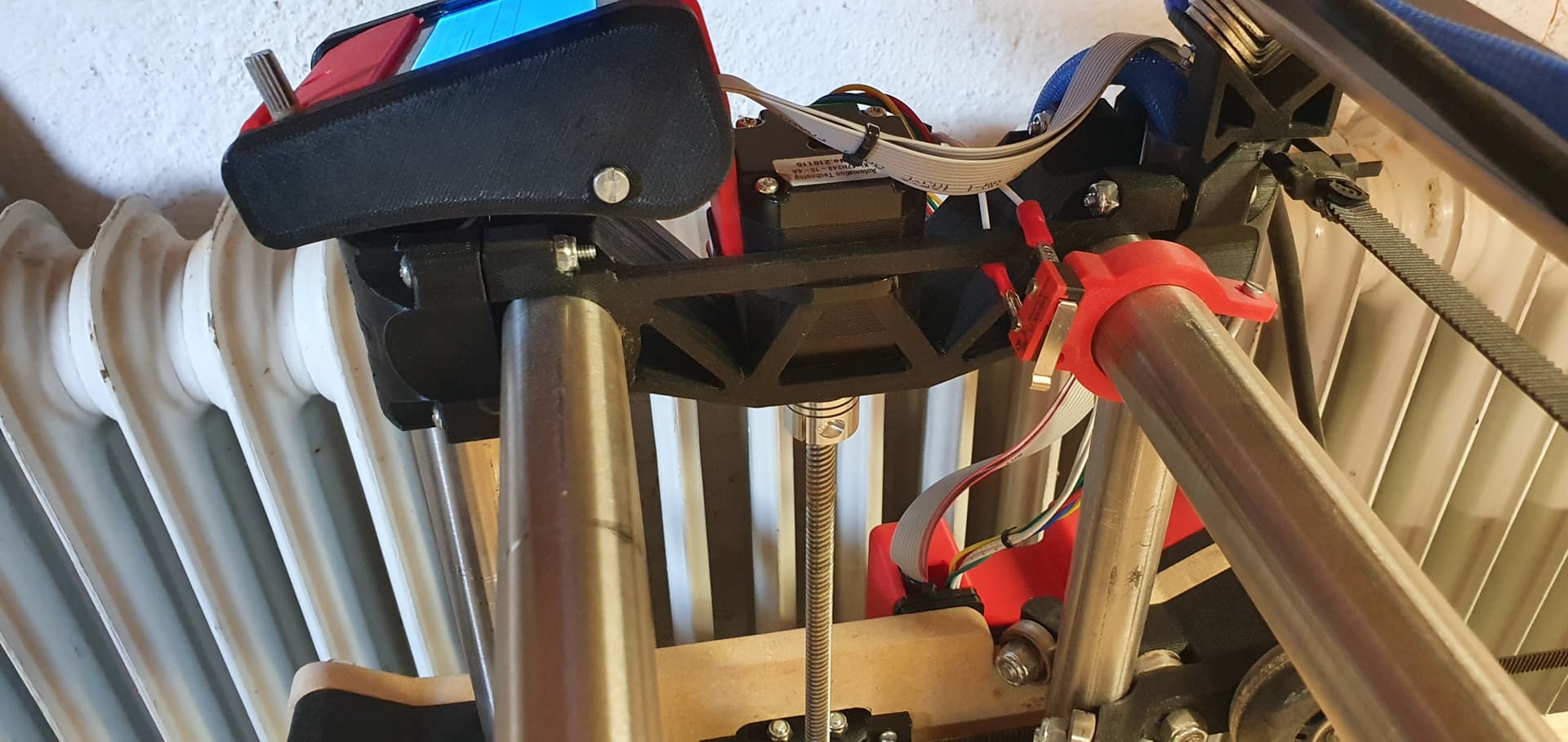
This is all one gcode file (so no homing in the middle, right)? So it sounds like the problem is either something is very loose, or you skipped steps somewhere. The Rambo has built in current control, and the setting in the firmware works for many other machines. Some other reasons it could have skipped steps are:
Binding somewhere. Does everything move smoothly?
maybe a cord caught something.
intermittent wiring issue (these are a huge pain to solve)
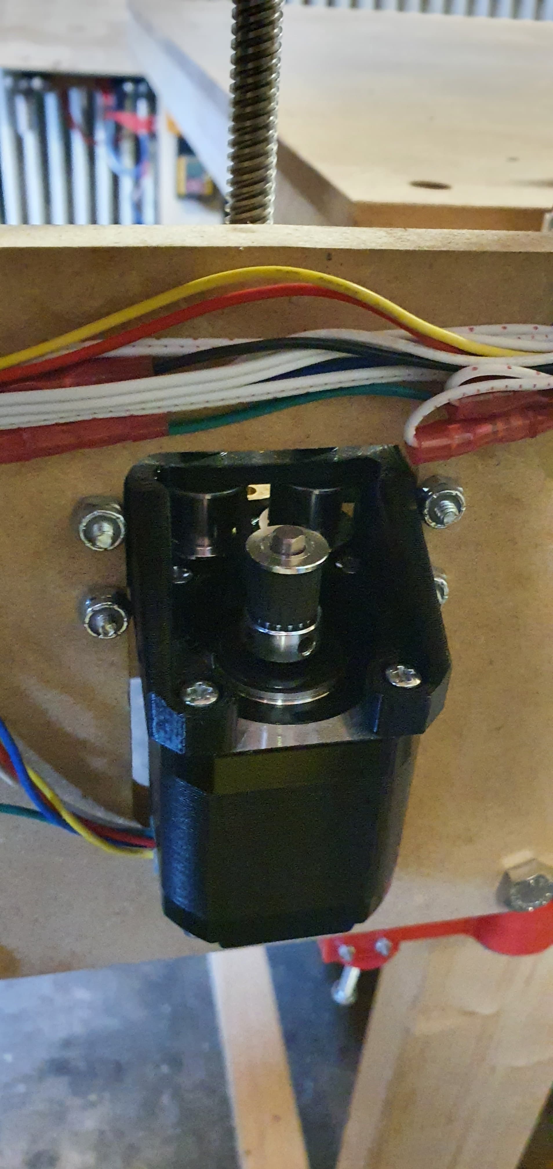
The pulley slipping on the motor shaft (check those grub screws)
too much load (1mm DOC is so small, it could only have been the drilling, but I doubt that even).
That frame you’re cutting looks pretty neat. I would like to see it when it gets finished.
This is solvable. This isn’t how it is supposed to work at all. Your LR will be screaming through jobs once we figure out what is wrong.
Feel free to post some pics of the build and the wiring and stuff. Maybe something is installed wrong and we can spot it.
Yes it’s true DOC is not deep, but I do not fully understand feeds and speeds or know my lowrider yet.
I went for the settings as shown under the milling guide on this page.
So my thought is, if I only take 1mm then at least I will not stress my lowrider until I can run some tests. I will try setting the DOC to 4mm instead. should I change my feeds and speeds then?
I use this bit. 1/8" Single Flute Carbide Endmill – V1 Engineering Inc
I actually bought one of each on the site.
My first toolpass was pocketing and then drilling. The first hole seems to be pretty ok and then it just gets worse and worse.
I use a poketing toolpass to drill so that it makes a small spiral and then pulls all the way up the hole (+ 5mm) to make sure that it gets chips out. after which it takes the next pass and so on until the hole is done.
I have not measured if all pocketing holes to see if it has the same distance, but at first glance it looks right.
To be honest I do not know where it has gone wrong, but at the moment it seems to be the y axis. have not made much other than my spoilboard, and some clams which has also given a lot of problems, but they are usable.
However, I have noticed that sometimes the x axis can “chop” a little in its movements, but it disappears again after a while. why I do not know.
If you have suggestions for upgrades, they are welcome.
Yes it’s all a gcode. no homing in the middle. The only time I am homing the machine is before I start my job, after which I set my work space to zero and do a z-probe.
I have not heard any skipping steps or noticed it. I wear hearing protection when I use it, as I used to be a musician and have a tinnitus.
So the ears need to be taken care of. But when I do not have the router turned on and running it back and forth there is no sound from skipping steps.
All my belts are tightened like a guitar string, so i dont know if I have tightened them too much.
I have also gone through all the bolts to se if they are tight. have even loosened them 1/4 as they seemed too tight.
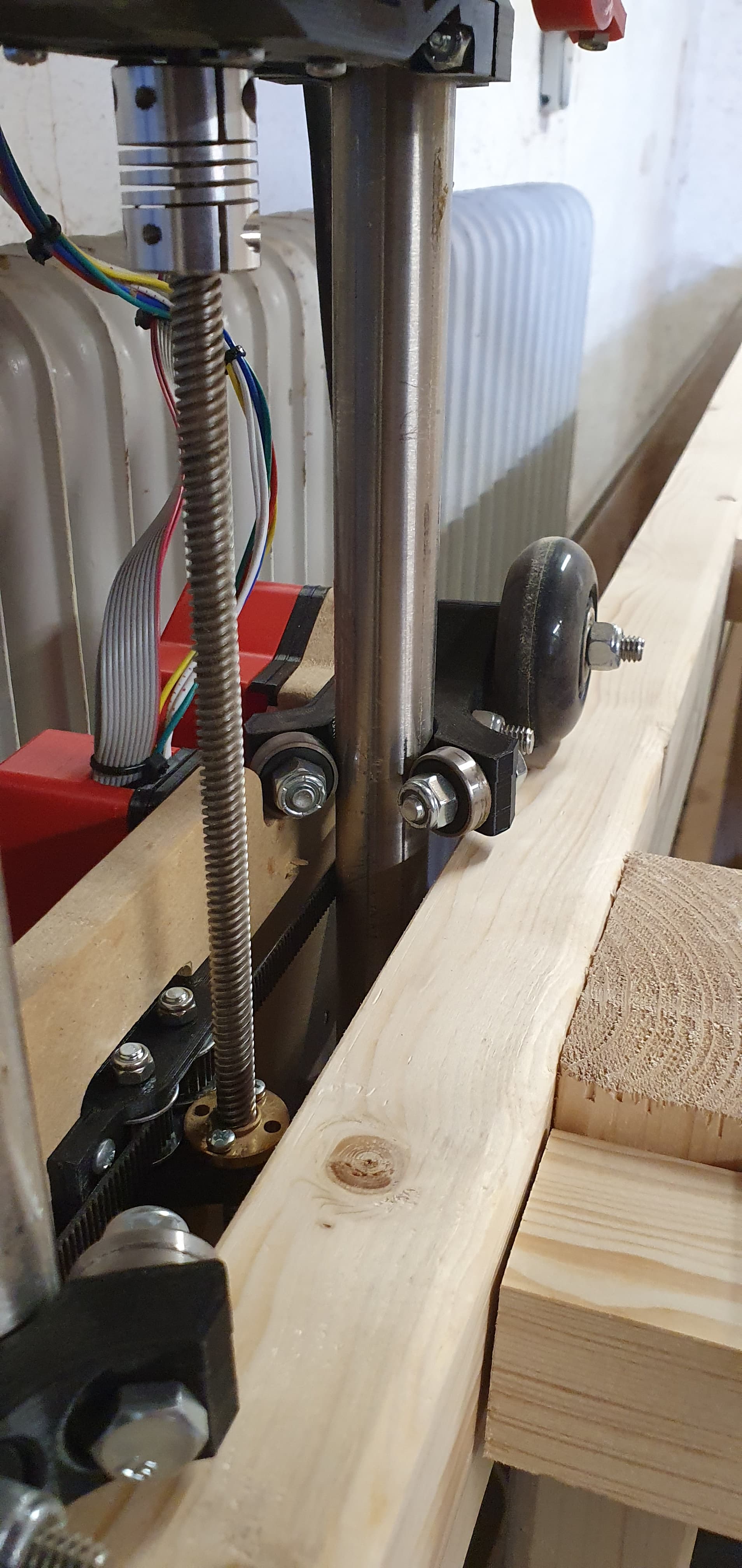
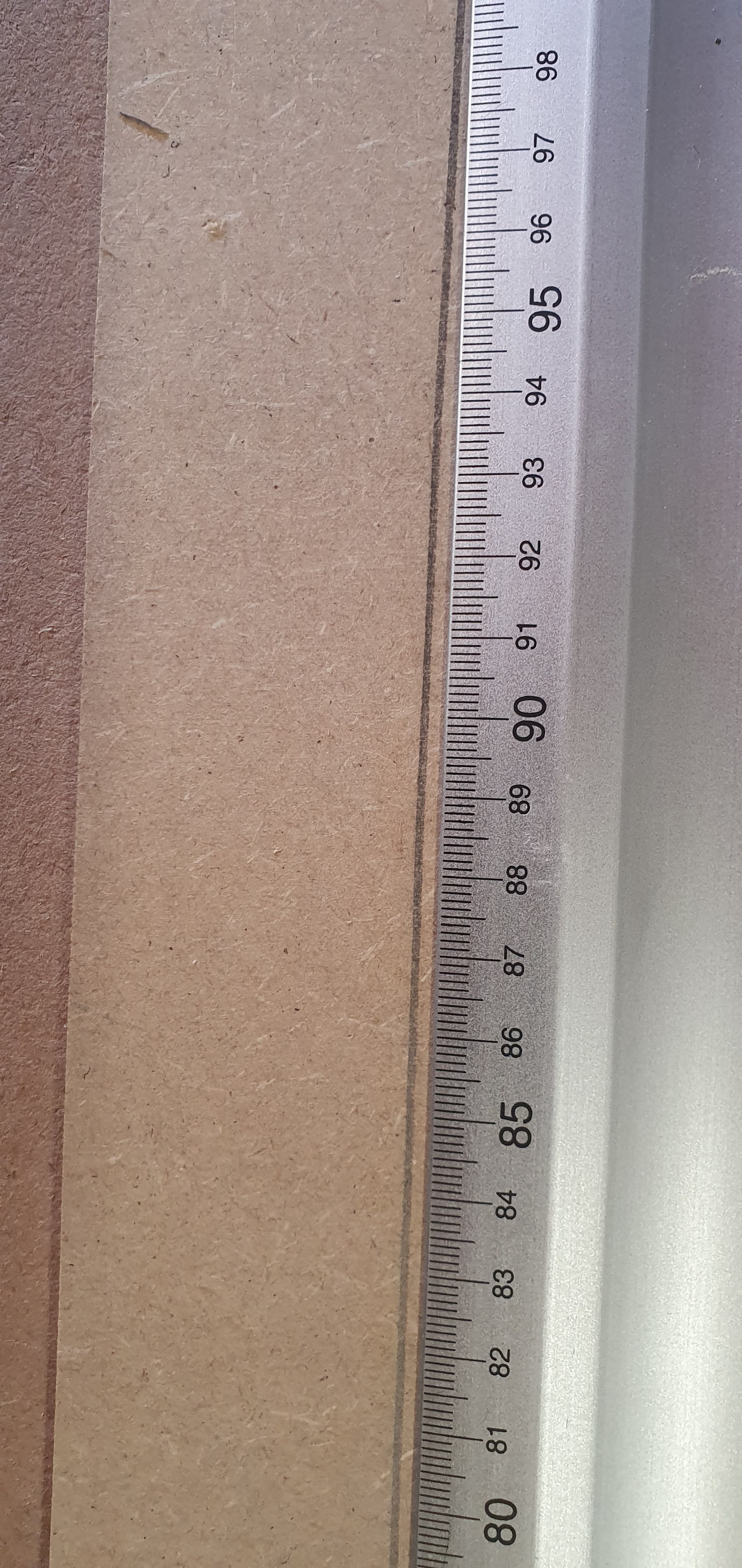
I have just been to the workshop and planed about 1.5mm of the table in the y axis. there were approx. 1-2mm space for z axis tubes.
Did not know if there may have been some inaccuracies in the wood due to humidity, although I had them through a plainer before I assembled the table.
When I do not have the belts on run it very smooth on the y axis but have som resistance when the belts are on. but not so I think it’s a problem … a bit the same as on my 3d printer
I have not had time to test if it has made a difference yet.
There should no be any wires stuck in anything. but I can install a cable chain on the y axis if that can help.
can the vacuum hose be a problem? can it be too heavy to pull?
I have also tightened the screws on the pulley, as you suggested, they were a little loose. But as I said before not tested it by yet.
I’m glad you’re confident, because I have to admit that I’m a little exhausted at the moment.
But I should probably just spend some time playing with the daughter and then come back tomorrow with new energy and report back.
It often helps to put some distance between you and the problem and then try again later.
I’ll take a lot of pictures tomorrow morning and then we’ll see if you can find a few bugs.
And of the fence, when everything runs correctly.
thanks for your reply and help.
I write when I have pictures and have been tested to see if it has made a difference with the changes
That’s a great conclusion. It will definitely get better.
You clearly have the skill and mentality to fix it. Your luck just means you will have to labor a bit more than others before you get it working.
I hope it was just a loose grub screw.
I would skip that for now. Just watch it work and be aware of anything that might snag. Cable chains can sometimes bind, and it isn’t obvious at all when they do.
Then I cut a few test cuts again, after the small changes I mentioned last.
I have planed the sides that the y axis run on to provide extra space in case the humidity should have bent the wood.
I have tightened all the screws for the pulleys.
Checked all the bolts, checked if my belt is tight enough. and set the DOC to approx. 4mm instead of 1mm. and run without the dustshoe and the vacuum cleaner hose on, and vacuum manually.
unfortunately it has not helped.
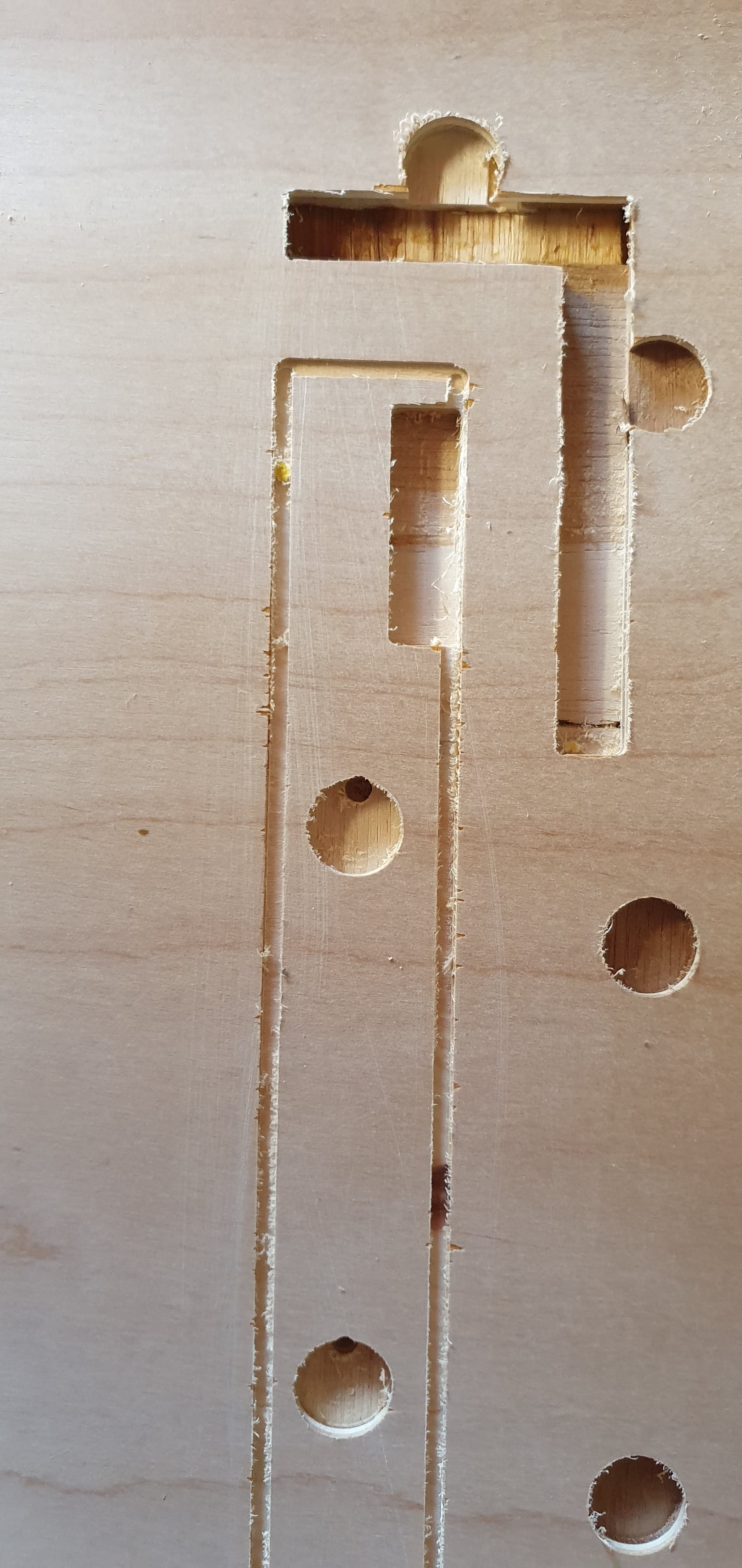
I then tried Estlcam 11, to see if there should be a problem with vcarve and the result is a bit the same.
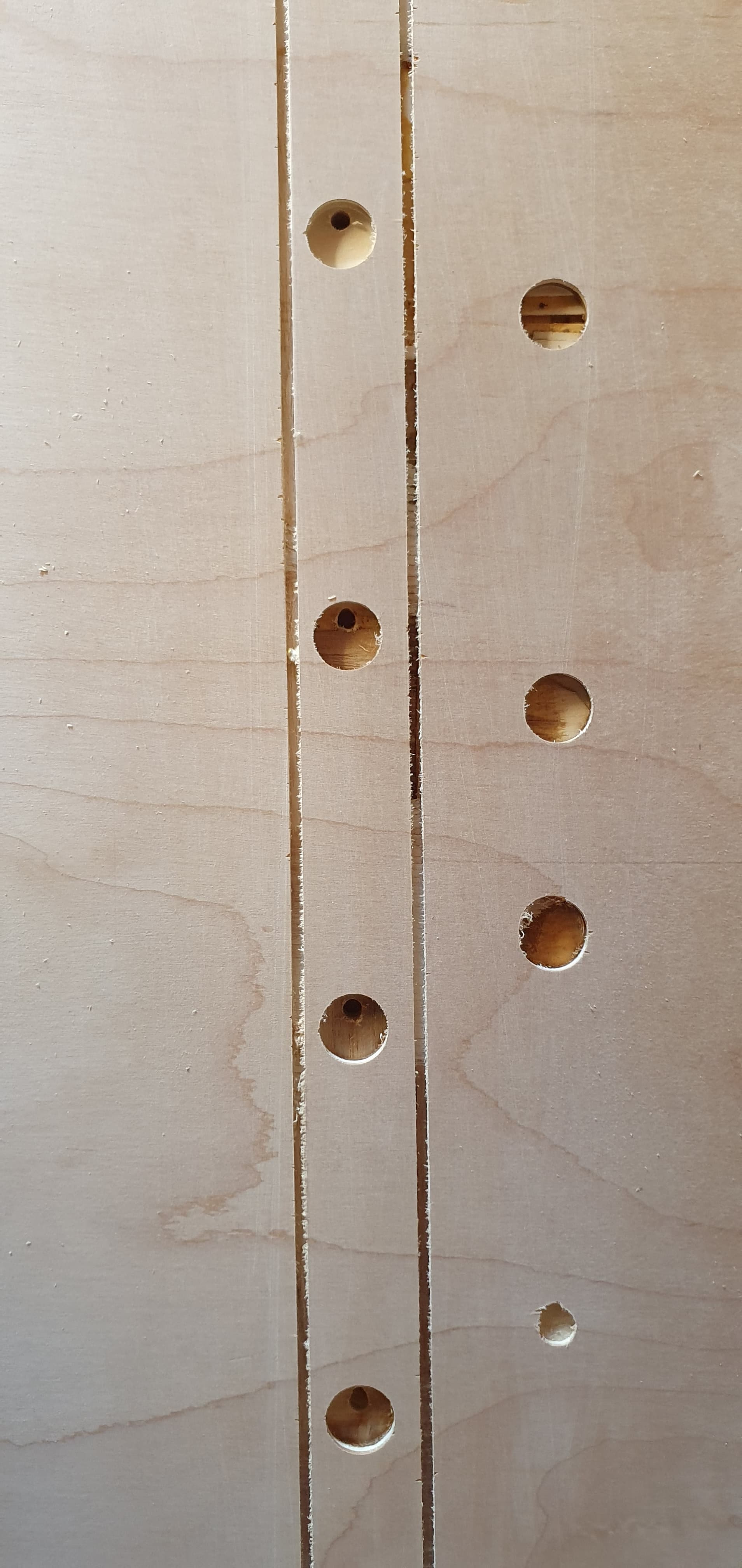
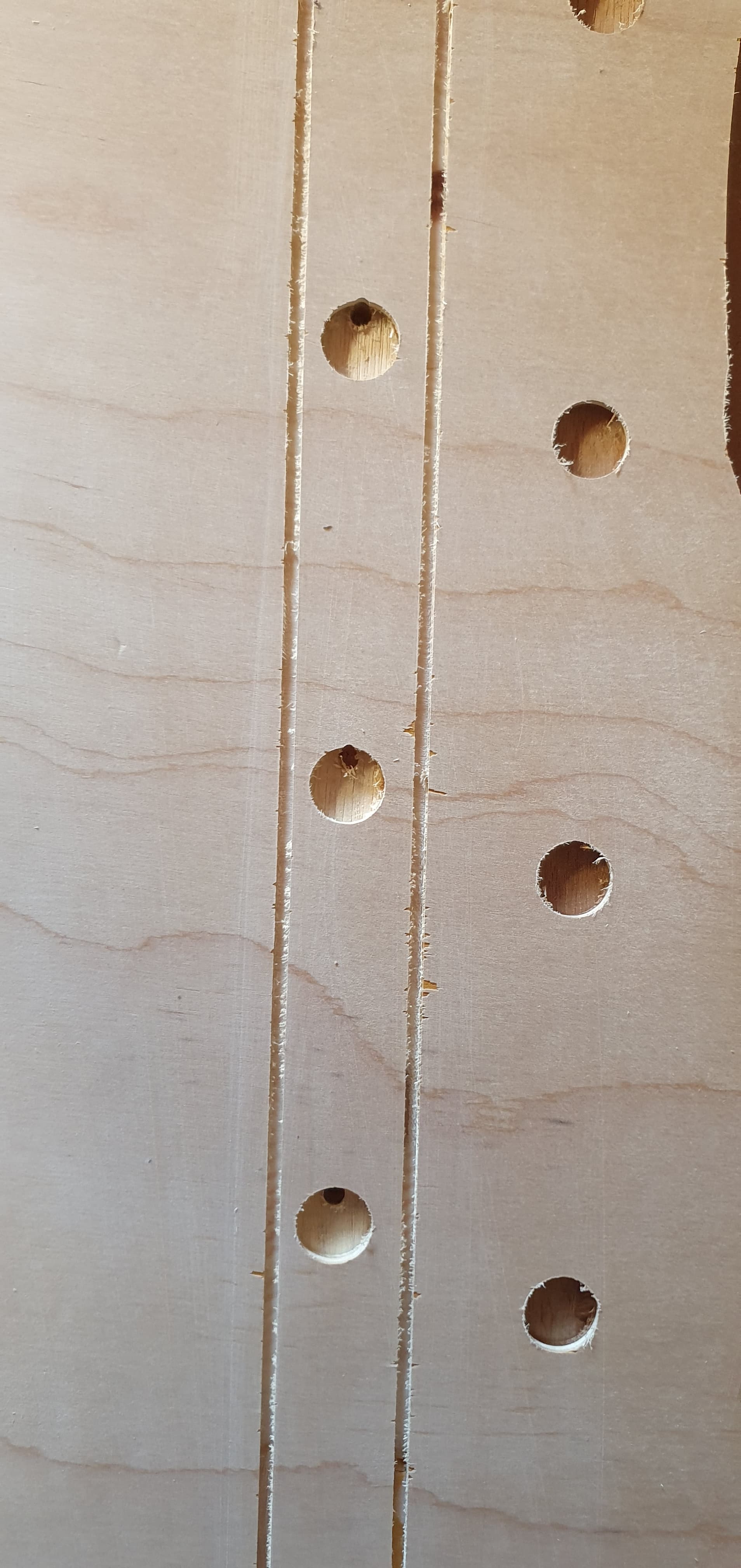
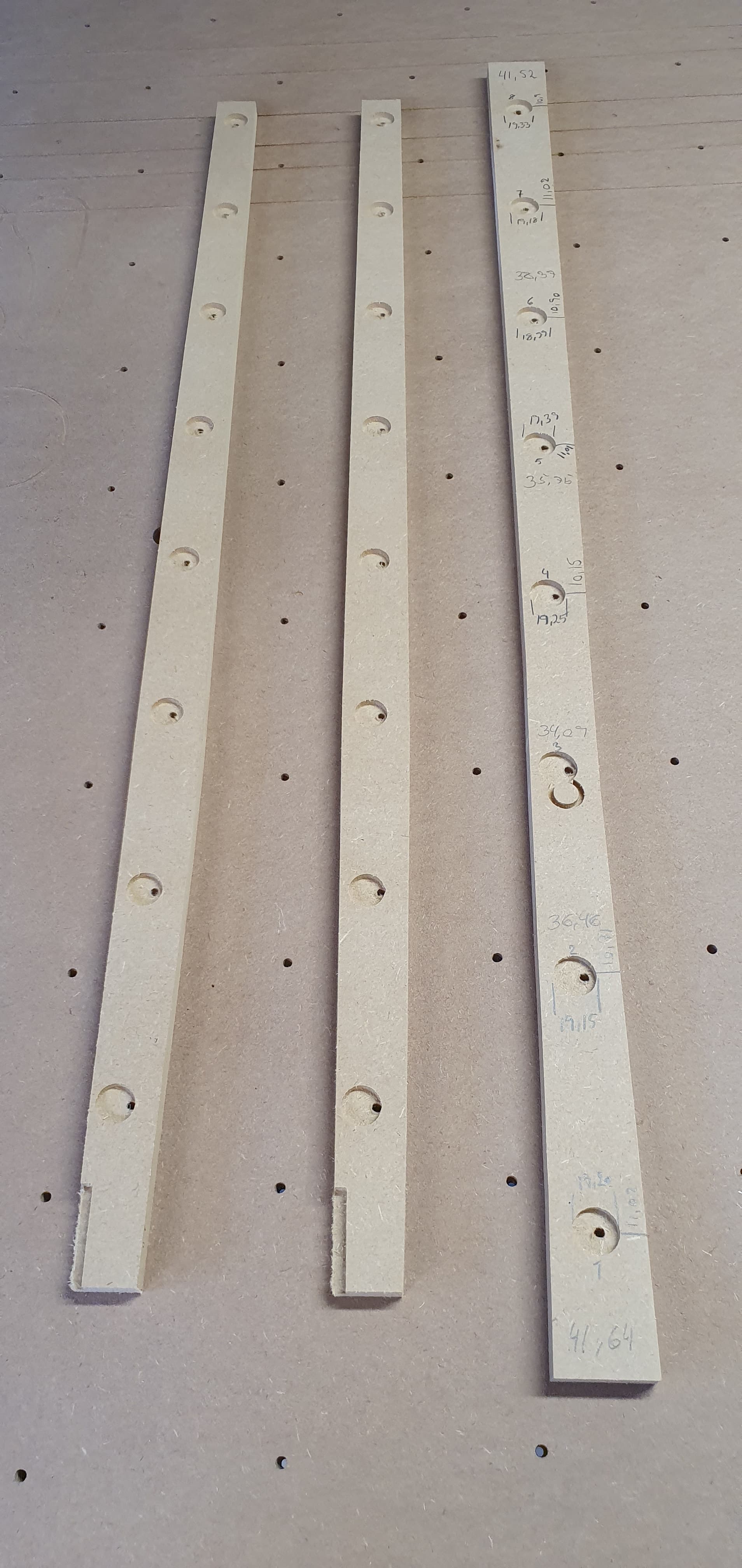
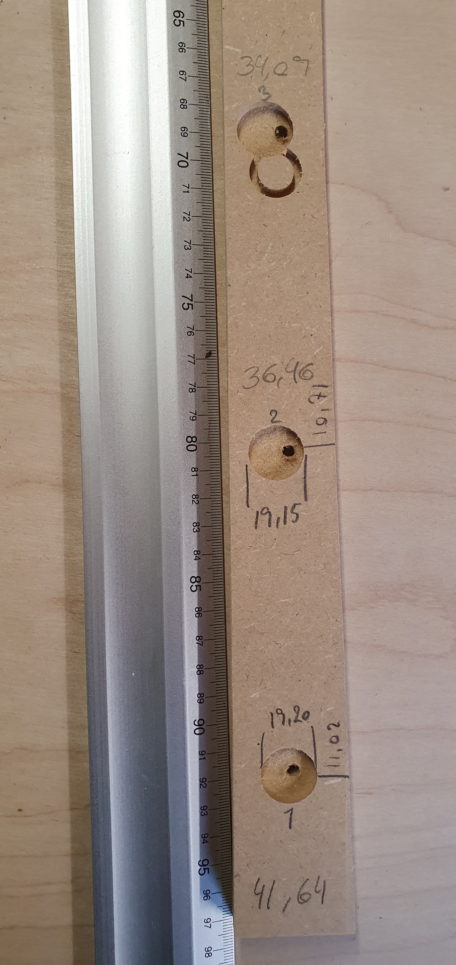
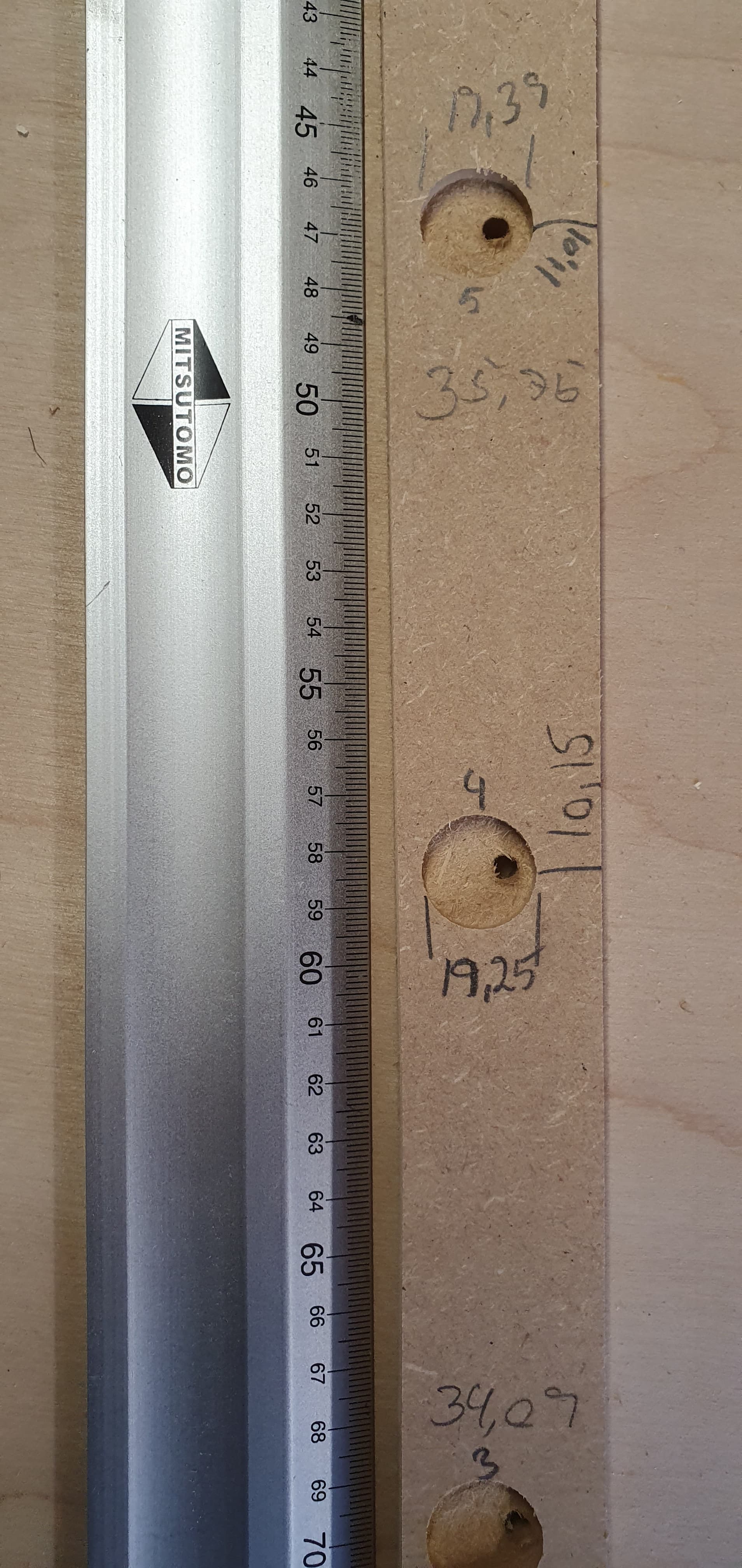
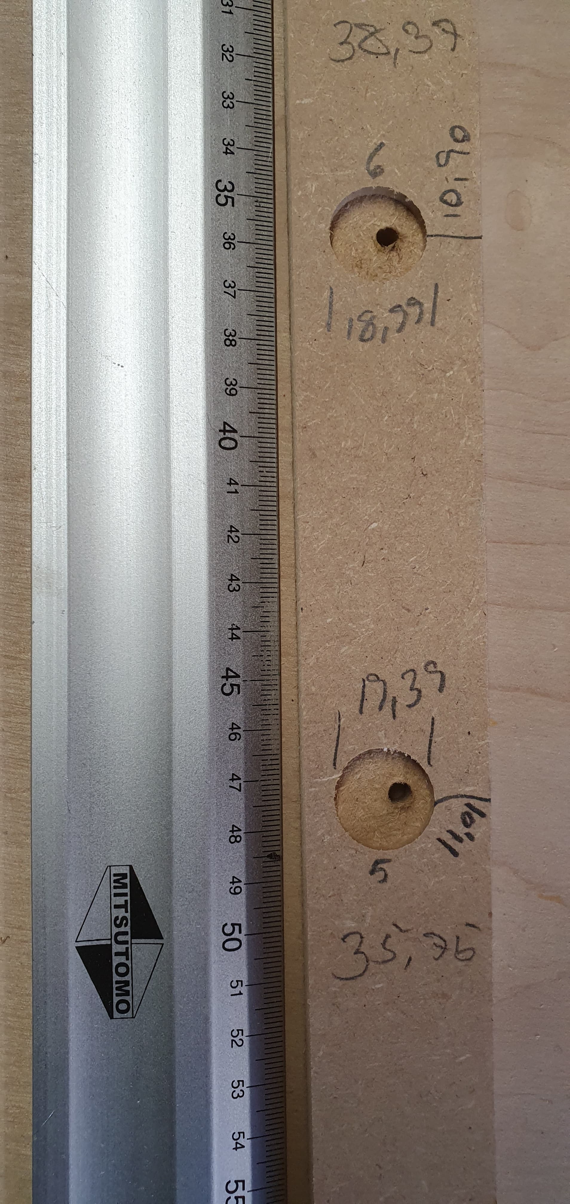
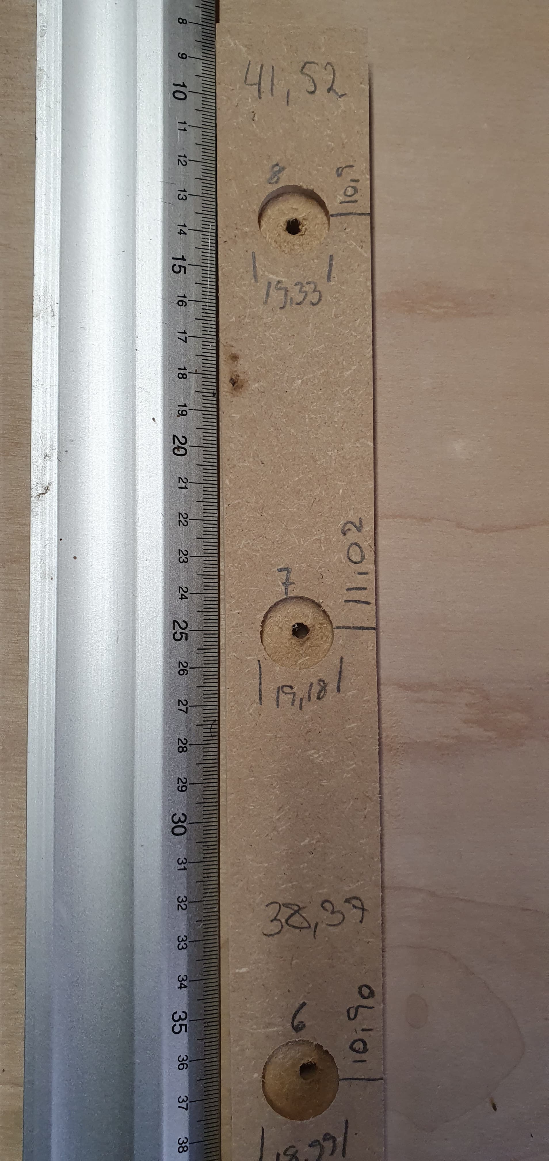
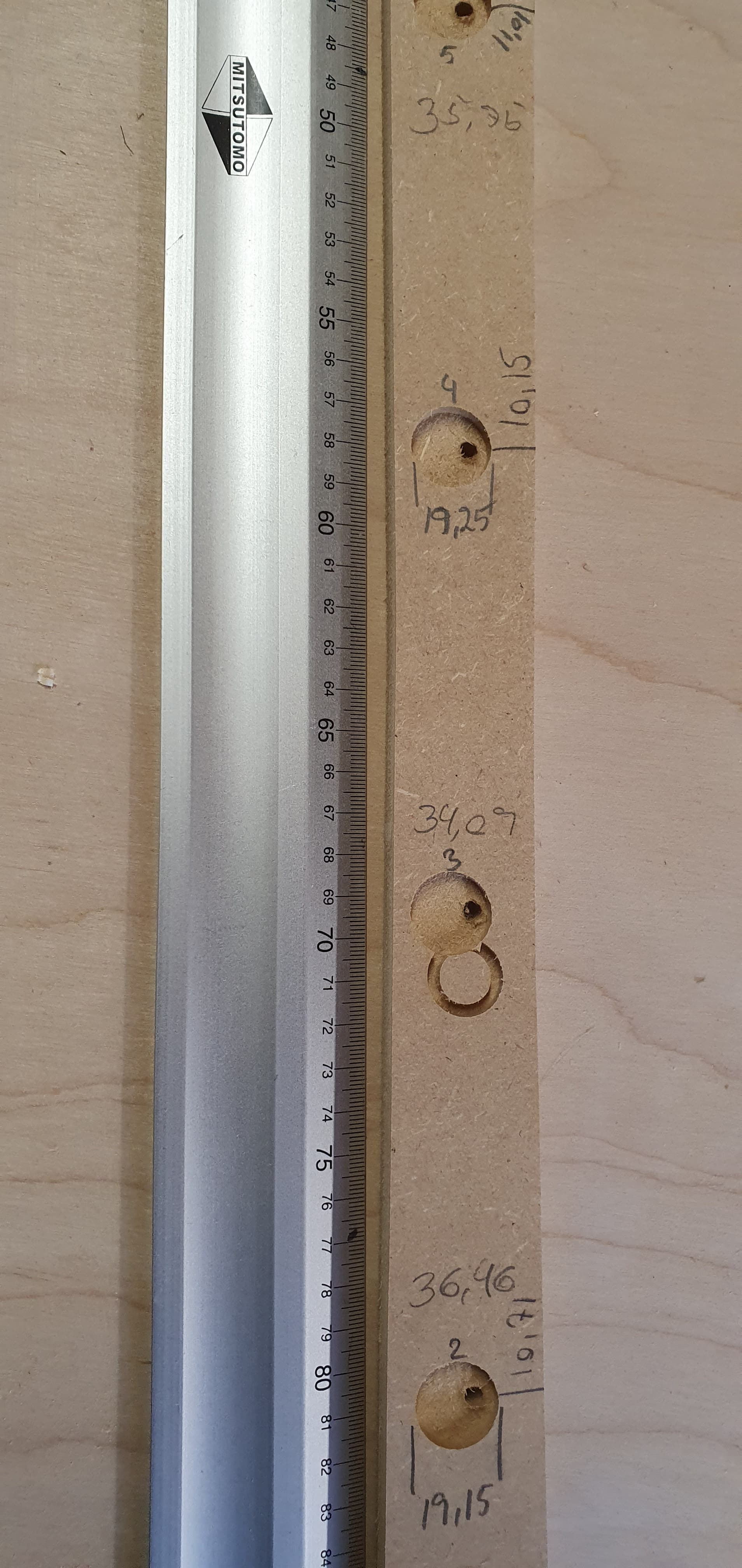
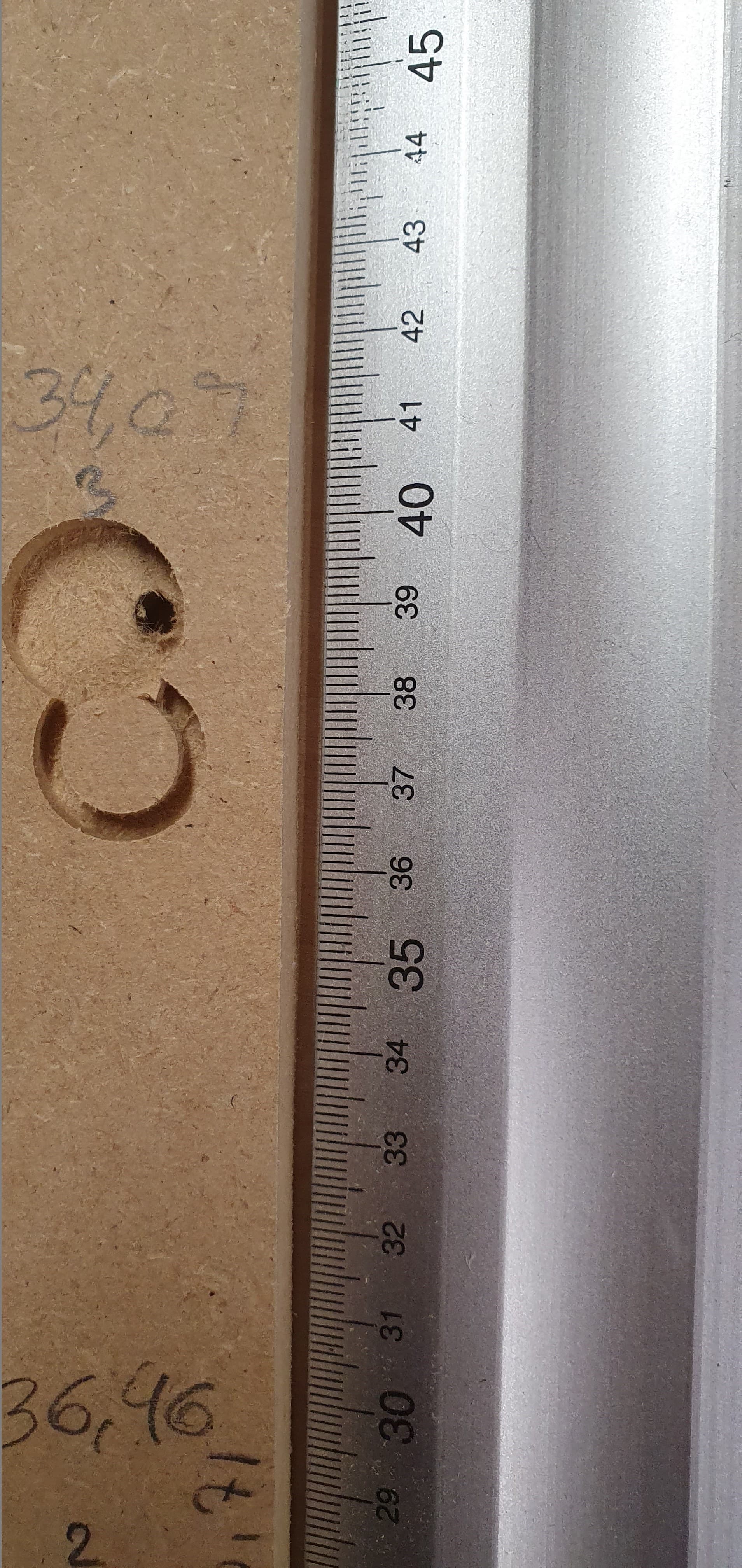
Then I made a new test drawing with the same depths and with easy measurements to remember. pockets must be 18mm with 5mm hole in the middle, there must be 10mm from the outside pocket to the edge of the profile on both sides and the profile is therefore also 38mm wide
as you can see in the pictures it is completely wrong and in addition it can not make a straight line along the y axis, but instead makes a curve. as shown in the last 2 image.
in addition, the extra circle at hole 3 is not something I have made a toolpass for and was also not something that I can see on my preview
The first 2 cutouts are made with vcarve and the last one is with Estlcam. I use CNCjs with windows via usb. Can CNCjs on windows be a problem?
I have also checked thoroughly for skipping steps, both by observing the belt and the stepper driver but also listening for strange noises. and I have not observed anything.
There have also been no wires or anything else that could have an impact on the result.
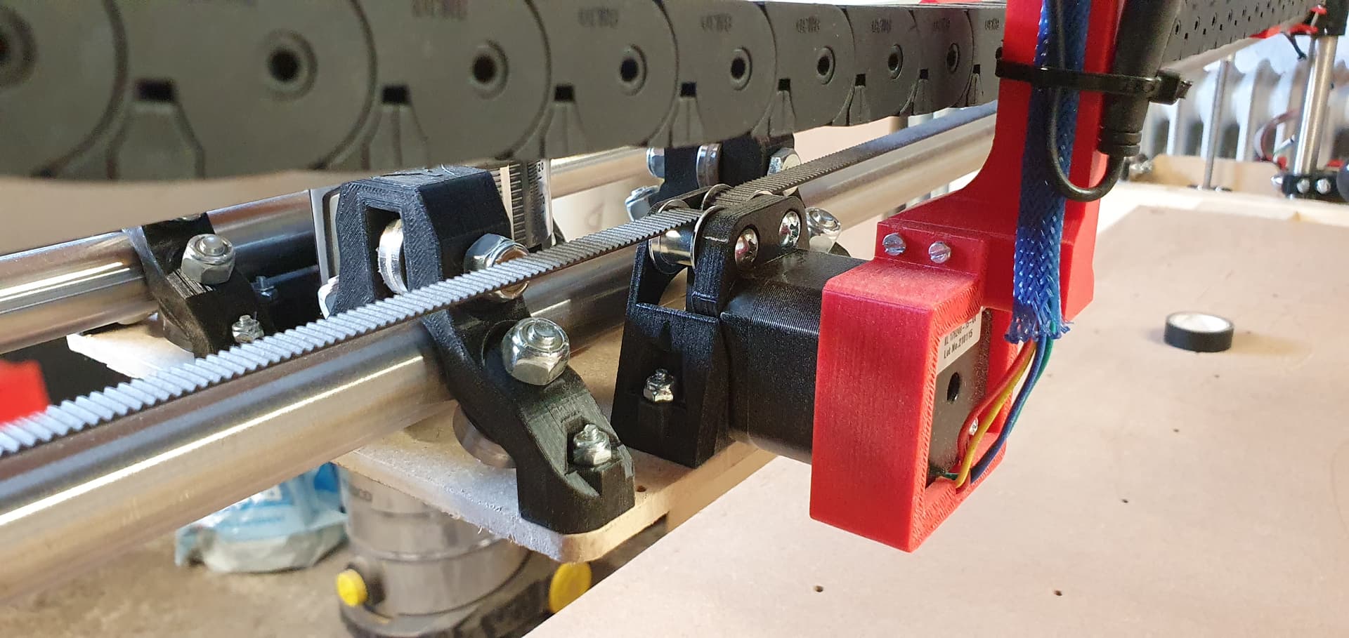
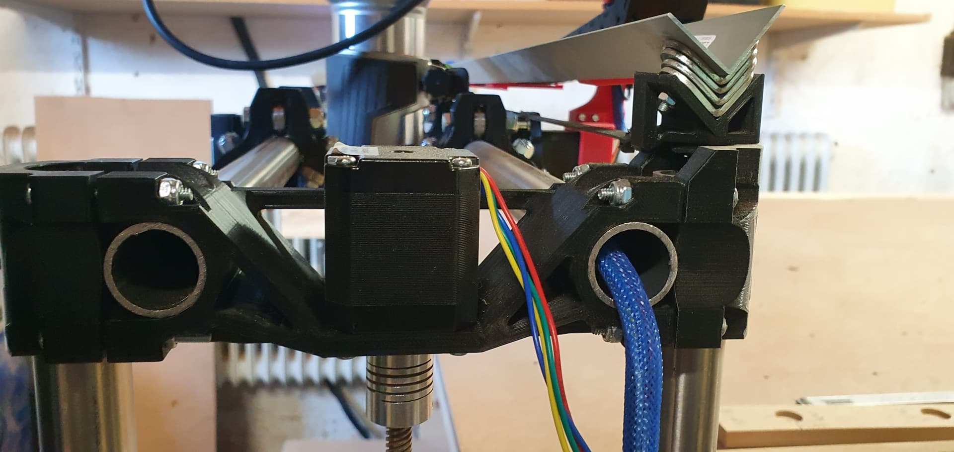
Here are a few pictures of my lowrider. hope someone can see an error that may be to blame for the bad result.
Just to simplify the issue, what happens if you just cut a single 100mm square. Measure the sides and the diagonals and see what you get.
Circles and drill holes and pockets can complicate the issue with additional cam settings but a simple square with a reasonable doc 4-6mm and feed rate of 6mm/s and a finishing pass of .5mm at full depth should make a pretty accurate square. If it doesn’t then the measured geometries should point to the culprit.
Ok since you have the pen attached create a circle and run it with the pen and see if it’s circular my guess is that it will be.
Next step would be to look for slippage/skipping steps, the standard issues are the ones Jeff suggested above grub screws, loose belts, parts rubbing, bearings overly tightened etc.
However, all these things seem to be ok.
I saw no skipping Steps, the belts, screws and bolts are tight and loosen 1/4. And did not se any rubbing parts.
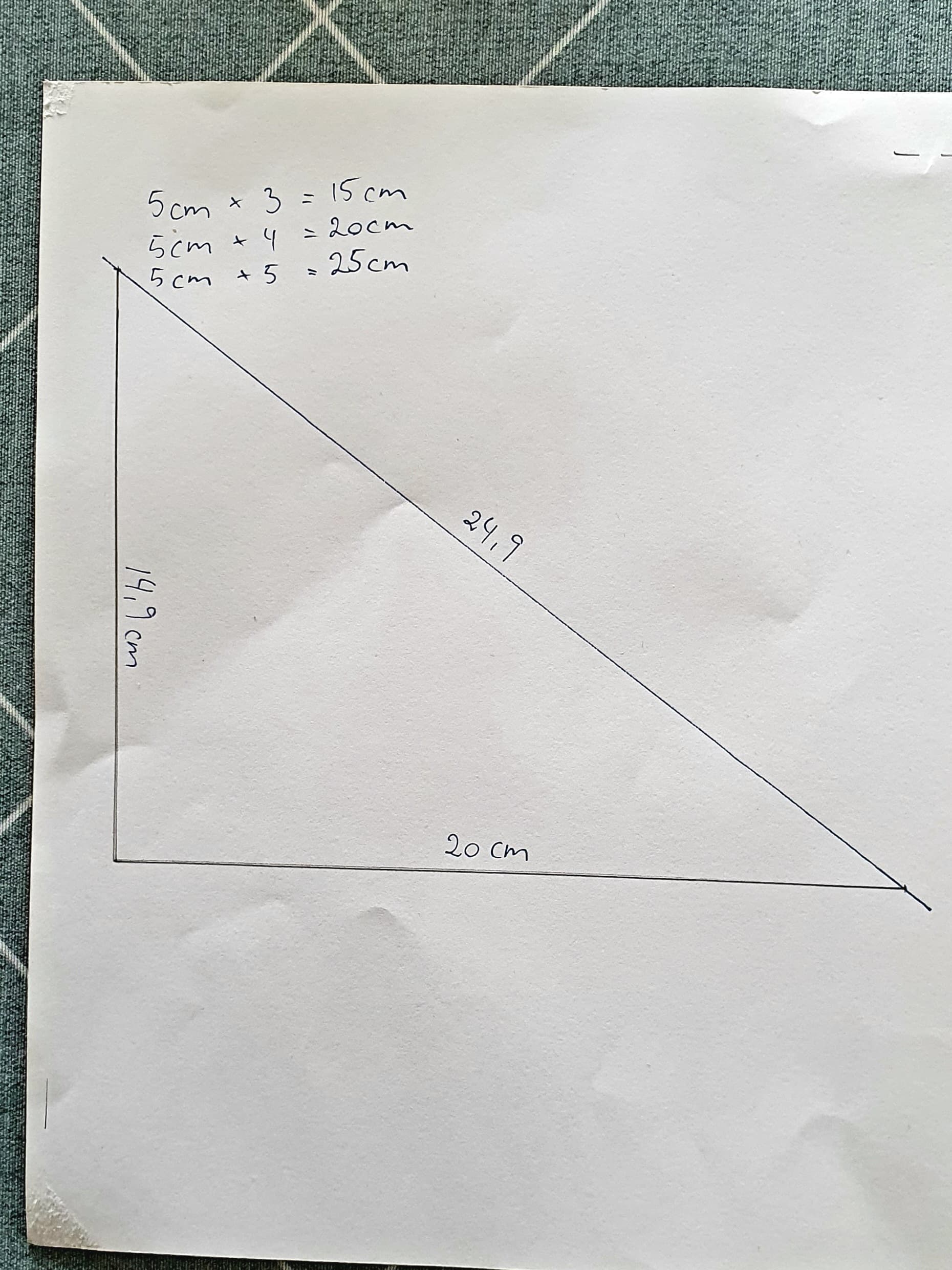
I made a much bigger test.
with “a” = 75cm “b” = 100cm and then “c” should be 125cm
“a” was exactly 75cm while “b” was 99.5cm. but again a curve that curves out towards the wheels. (see the picture)
I calculate those numbers and the hypotenuse (“c”) should be 124.6cm. but I measure “c” to be 124.8cm… so not right-angled. About plus 0.2 degrees… it may not sound like alot, but that is, an inaccuracy of about 4mm per meter.
but personally i think it is the curve that is the problem. if it had not been there, the 99.5cm would probably have been 100cm and thus a right-angled triangle.
a small addition. when i ran my first test i noticed a faint click sound from inside one y axis stepper motor. that is, the one to which the curve points to. while drawing in the x-axis direction … that is, the y-axis did not move, and should not move, while the clicking happend.
I ran a couple of test to see if it repeated itself, there was no noise.
Perhaps you could shorten the X gantry a few mm so that the Z tubes lightly brush the sides of the table.
This way the wheels will not be able to translate in an unwanted way.
it is an option. but if I do that, will it not cause problems with changes in temperature and humidity and its impact on the wood from which the table is made of.
I live in Denmark and there are large fluctuations between summer and winter
Hej Henrik
Jeg har haft samme problem, hjul glider til en af siderne. Lagde en stribe af kontakt lim, for at se om friktionen ville blive bedre. Det hjalp
Mange tak…
Jeg har brugt et par vinkel profiler på begge sider af y aksen. Men har ikke haft tid til at teste det endnu.
Men umiddelbart lader det til at hjælpe på det.