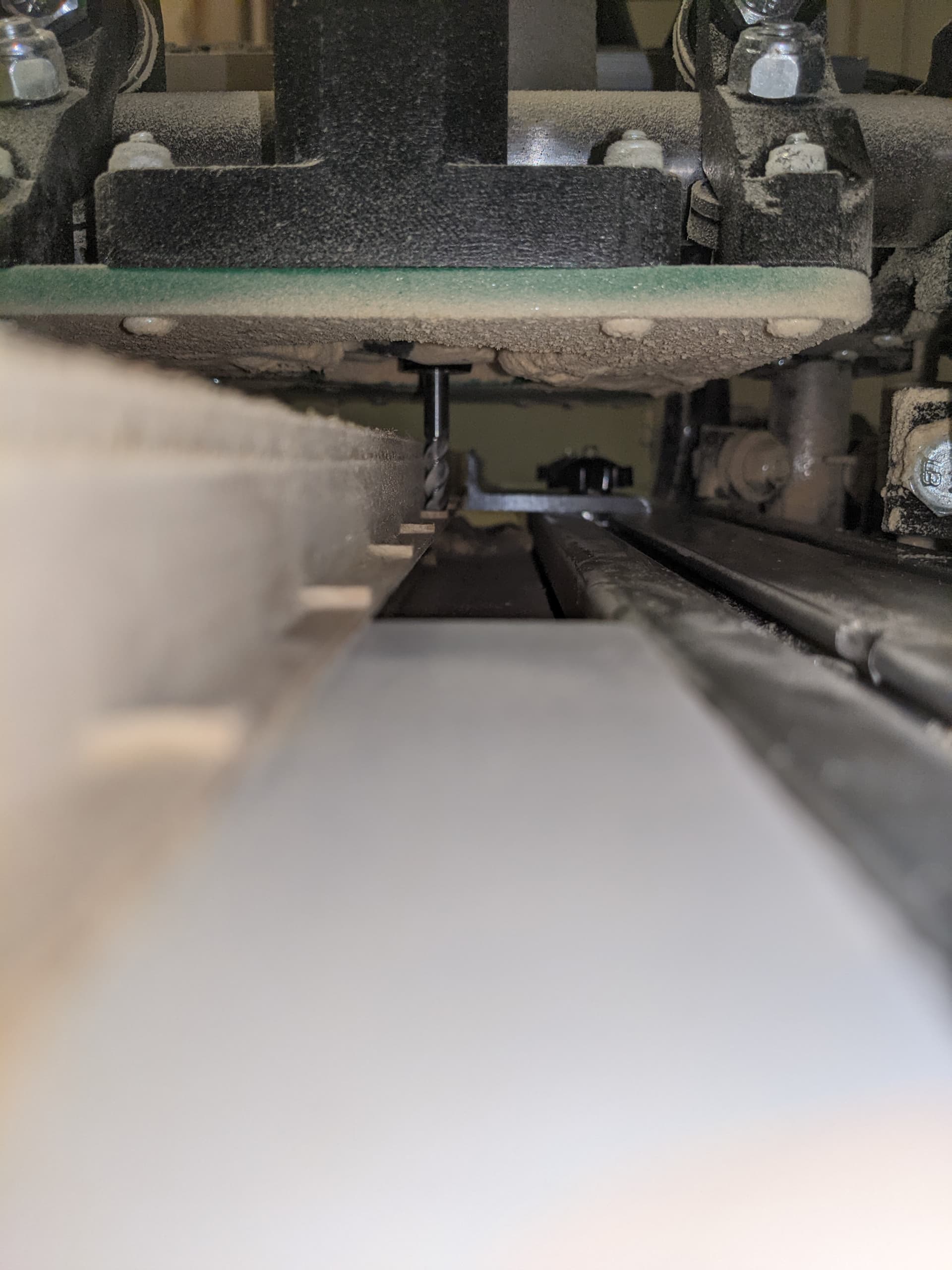
The 2D Contour operation finally completed, but it left 1.35mm of the stock, not cutting all the way through. My friend Kim told me to check to make sure the router bit extended past the X-axis platform, which it does as shown below. It is 1-1/4"+ past. This was to rule out the platform preventing cutting to the full depth.
I just looked at the gcode and it appears that the Z is never set to 0 (bottom of stock). The lowest it goes is 0.575. So that is 40% of the missing cut. I looked at my Fusion 360 model and it is 19.05mm or 3/4" as that is what the MDF is. Since I specified the bottom of the material to cut away, it isn’t clear why the operation did not clear all the way to Z0. Thoughts? I could very well have incorrectly configured the CAM operation. That still leaves 0.775mm.
I have the touch plate (from the v1engineering store) installed and configured. The Rambo 1.4a has the Marlin DualLR firmware installed. The X and Y positions have been set to the origin of the stock and G92 was used to set them to 0. In the event, I am using it incorrectly, here is how I use the touch plate.
The Z-axis is raised to 60mm.
Using needle nose pliers, the clamp is attached to the bit.
The Z-axis is lowered to 5mm from the stock.
The plate is slid under the bit and pressed tightly against the stock.
The “G38.2 Z0” is sent to the Rambo. The Z-axis lowers and stops at the touch plate. It does not raise on its own.
“G92 Z19.55” is sent to the Rambo. This is the thickness of the MDF (19.05mm) + the thickness of the touch plate (0.5mm).
The Z-axis is then raised to 60mm and using the needle nose, the clamp is removed.
The gcode file is then queued and execution is started using the Repetier-Server. Anything look wrong with that? What else could cause the CNC not to cut all the way through? Thank you
I don’t see anything directly wrong with your process/code, but you are using the top of your stock as your probe reference. I find that most stock varies in height. A better (and simpler) way might be to use the top of the spoil board as your reference.
Use the touch plate and the G38.2 on the spoil board
Execute a G92 Z0.5 to account for the touch plate thickness
Raise the bit above the stock and move to the XY corner you specified in the CAM
Run the file
This assumes you authored the CAM using the bottom of the stock as reference, and that you authored your toolpaths to go to the bottom of the stock.
Assuming your spoil board is parallel to the travel of the router (i.e. you are lucky or have surfaced your spoilboard), your bit should just kiss your spoil board.
@robertbu I see your point about using the top of the spoil board. I will do that from now on. I did double check the stock thickness and it was spot on, but I will try the top of the spoil board and run the job again in the morning.
Are there any reasons (off the top of your head) that the generated gcode would not, at some point, be cutting down to Z0? Why stop at 0.575?
I can think of ways to make the g-code not cut all the way down, but they would not happen by default. For example, you can set the bottom height of a toolpath to be above the bottom of the part, or set an axial stock to leave.
It is easy enough to check the g-code to see if it is cutting all the way down. If you post your g-code file here, I’ll take a look. As a first check, take a look at the contour toolpath in Fusion 360 from the side and see if the blue line is at the bottom of your part or not.
I can also take a peek at the Fusion 360 file to see if I spot anything. If you put it in a ZIP file, you can post it here.
F360 probably has several different possible reasons it could produce code that doesn’t hit the low point on z. First thought that comes to mind is “Stock to Leave” is enabled… but that’s too obvious right? Maybe there is some weird fixture config in the setup, where it thinks that’s off limits? Did the cam job in f360 generate with a green check mark (ie no minor cam errors)? If it’s green, we’ll need to dig deeper into the setup of your contour cutting operation more I think.
It sounds like your probing/coordsys setup is done right. Whenever I have issues like this I find a quick sanity check helpful… command the bit to top of stock and verify it’s where you expect it. Either way though, if your gcode never gets to z=0 then you can’t expect probing or other hardware measures to fix that.
Regarding where to home z… spoilboard, stock, etc… from my experience it doesn’t matter if you know your setup. Ideally you would also measure your stock and model it in f360 (not every time… just when it’s required hehe). This way, regardless of where your probe is setup your cut will always be in control. You may get away with just spoilboard homeing and thickness assumptions for stuff like MDF, but say you got a bar of aluminum that is 0.1" thicker than expected… you better account for that before cutting.
I wish I could mark both your answers (@robertbu@truglodite) as solutions. When I checked the blue line it was not at the bottom of the stock. For some reason the stock got set as 20mm, not 19.05. That is almost a whole mm. Then the Stock to Leave WAS checked, but it was only 0.1mm. The blue line is now the bottom of the stock. Yay! So now I will recut that piece using Robert’s Z-leveling from the spoil board. Hopefully all the positioning will be the same. Thank you, thank you both.
I have found when I use Ryan’s metal spatula for touching off the z-height that my cuts stop that thickness short of going to the bottom I just always forget to account for that when I produce my G-code
You need to offset your work coordinates by the thickness of your touch plate. Not sure what sender you use, but in bCNC I just type in to the z wcs, hit enter, and it updates the origin. AFAIK all senders should be able to do the same.