Hey Guys… I am a total newbie to CNC. I have never worked on any CNC equipment or created any. I recently got myself a dismantled MPCNC kit of used parts. I followed Ryan’s step by step instructions and managed to re-assemble it together without any issue. I also got the Crown plotted successfully.
The controller is MKS v1.30 with Marlin v1.1.9 & LCD is configured with Auto Square feature for X and Y axis. When I turn it on, it displays MPCNC v2 and everything seems to be working fine mechanically. I can home X and Y and move the axis. As for the Z axis is programmed to home at +5 and the travel is limited to -20.
I tried to connect EstlCAM to my controller using the Arduino options but no luck, but I can connect using CNC.js and Pronterface.
I created a simple rectangular panel milling using Fusion 360 (also newby) and exported the G-Code and uploaded it into Pronterface and when I run it the Z axis starts to move down and if I don’t power the CNC OFF it tries to dig itself into the workboard which is a 3/4 inch MDF.
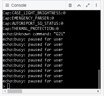
I later found Guffy’s PostProcessor and used to export the G-Code from Fusion and the issue I seem to be having is it complains about G21 unknown command? Which I beleive relates to changing the mode to mm but my Fusion settings are already in mm.
The G21 error is a red herring. It will just keep cruising after that.
Not connecting with estlcam is normal. We use it for cam, and just export the gcode, like you are doing with fusion.
Pronterface can control the printer, but IIRC, it has trouble printing if there are no extrusions in the file. Pronsole works. So does repetier host.
The digging into the work is probably because the origin isn’t set right. You need to set the zero position on your workpiece in the CAM and also in the firmware.
I did some troubleshooting of the Fusion G-Code and I found the issue to be linked to the command M0 Turn ON 15038RPM in the Fusion G-Code. I REM’d it out and it solved my problem.
Yes, i think you are right. It was in DOS BASIC and in BASH it was used for Remark. You can guess how old some of us are and still trying to dabble with software and hardware stuff
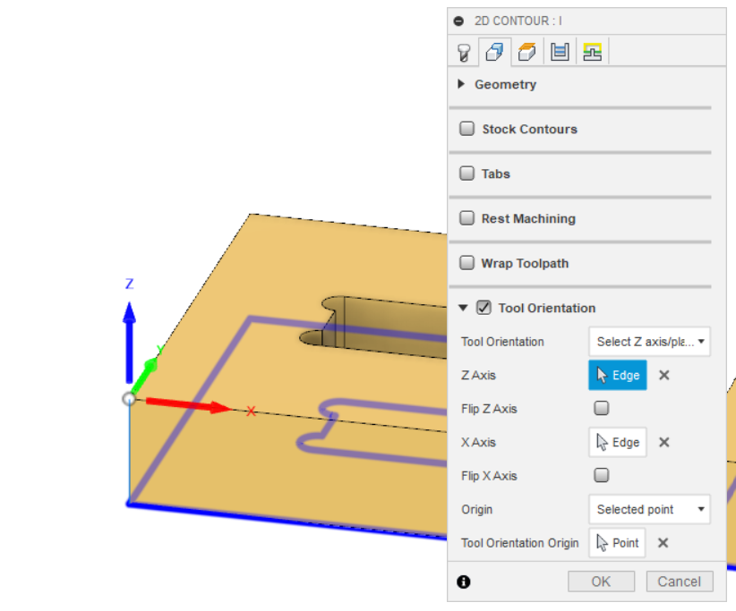
Another pitfall with Fusion is setting the origin. There’s three (!) different ‘origins’- The model origin, the machining origin, and the tool origin. It’s possible to build the model with the ‘top’ plane on the Z axis, then set up your machining workspace with the ‘top’ on the Y axis, then actually tell your toolpath that the top is the X axis. All very confusing.
My method of working is to set the origin and axes in the toolpath. It’s under the ‘tool orientation’ option within the geometry tab of your toolpath settings. Once you’ve got your axes around the right way, make sure you set a point on your model, not on your stock, as the stock is often a different size to your model.
Thank you so much for sharing your method of how to set the origin. I am still trying to figure out how the geometry of the toolpaths work and relate etc. Getting ready to cut my very first piece
I just went through this process, so I feel your pain! I’m coming out of F360 into Repetier-Host. One of the big conceptual leaps that I had to make was to think in terms of my stock piece, not the model. So I always have a box of some sort, with the part carved out of it.
Whatever your actual modeling program is, make sure that your model’s pivot is set at the lower-left-hand Bottom corner. This helps when importing. I use Insert/Insert Mesh and drop in an .stl. Go to Manufacturing, and click on Setup. In the Stock Tab, set all offsets to 0. Go to the Setup Tab, and set the Box Point at the lower-left-hand Top corner. This will be the place that you set your physical bit as Work Zero.
I came up with a 3D printed locator for Work Zero that is performing nicely. I’m able to reliably set Zero, even through tool changes. Check it out: CNC Work Zero Locator