If you ever have the opportunity, the Reno Air Races are worth the trip, I’ve had videos but nothing that does justice to the sounds. The P&W 4360s (28 cylinders, 4 rows of 7) and the Merlin V-12s coming by at ~ 500mph are just amazing. Seeing an uncowled 4360 is seeing the definition of complexity.
That sounds like a blast. Put it on the bucket list.
I did get to see a few aircraft operated by the Collings Foundation a few years back when they came to town. I saw their B-17 “Nine-o-Nine” take off and land a few times, as well as their B-24 “Witchcraft”. It was a really cool experience, and I was able to take my son which was even better.
Sadly “Nine-o-Nine” crashed shortly after takeoff a few months back, taking a few lives with her. Just awful…
My Dad was aircrew in B-26 Marauders during WW II, I’ve had a lifelong interest in aviation. Always a heartbreaker to see the loss of any aircraft, worse when there’s loss of crew. I don’t know where you’re located, I grew up in the NYC area. Not too far up the Hudson valley is one of the neatest places I’ve been: Old Rhinebeck Aerodrome where you can see WW I aircraft in action. I’ve always been a fan of round engines and many of that era were rotaries, the crankshaft is bolted to the firewall and it’s shocking the first time you see the ground crew go to start the engine, as they pull the prop thru the cylinders go along with it.
I notice you’re not using the traditional arrangement of a master rod with the others pivoting off it with your radial. Will you be using single rods on a single crank throw?
I’m in South Florida, but my family was originally from the New York suburbs, around Rockland county. My grandfather was an aviation enthusiast, aircraft builder, and private pilot (not by trade). That is probably where my love came from. In his later years he used to take me to the RC field to see his planes fly. I also had a great uncle that was an aircrew on a B-25 Mitchell during the war. I didnt know him very well, but it was cool seeing his exact plane at an airshow when I was a kid. He was among the lucky few to fly 25 missions and come home early.
Actually I am using the master rod arrangement. The rod with the slot in it is the master. Forgive me as I dont know all of the radial engine terminology yet, but this rod will attach rigidly to what I am calling the “crank plate”, while the others will attach to the same plate, but through a bearing so they can pivot with respect to the plate.
He was, the number of missions before going home was quite flexible, my Dad wound up with 55 before coming home. I had the opportunity to meet some of his crewmates when I was a young boy, those men were and still are my heroes.
Ah, I understand about your ‘master’ rod, I tend to think in terms of internal combustion and your engine’s a bit different being solenoid driven. I’ve fooled with engines a fair amount but never a radial. They’re very different, most 4-stroke engines will have a camshaft, a radial basically has a ring with bumps on it. I marvel at the things that have been made to work, especially in the days when things like metallurgy were by guess or by golly and computers didn’t exist.
Yeah, I am going to attempt to control timing completely electronically. No lobes and contacts, but power MOSFETs and a microcontroller. I am hoping that I can control the timing effectively on time alone (in other words, just fire every X milliseconds). If that doesnt work I may need to add some sensors to judge crank position. Trying to keep the microcontroller (and thus the number of needed I/O ports) small.
That’s interesting, far removed from my knowledge base but I’ll be interested in hearing how it works out. I know there’s been work of actuating valves by solenoid rather than camshaft but AFAIK nothing’s made it into production, yet. Reciprocating engines fascinate me as there’s so much going on compared to something like a turbine.
Hardware store aluminum doesn’t help  Hooking up a constant air blast to clear chips from being re-cut will help significantly with the chip welding. If that doesn’t fix your issues look into trochoidal toolpaths. They’ll take 3x longer but are very forgiving and you’ll be able to take full depth cuts.
I’ve been using a manual air blast, and I have tried trochoidal as well. I couldn’t quite get to full depth. I think some of my issue was how thin the material was, meaning it heated up quick. Also my tools have alot of aluminum build up that I could t really see until I took them to work and looked under 30x power microscope
I have some single flute mills coming in the mail today.
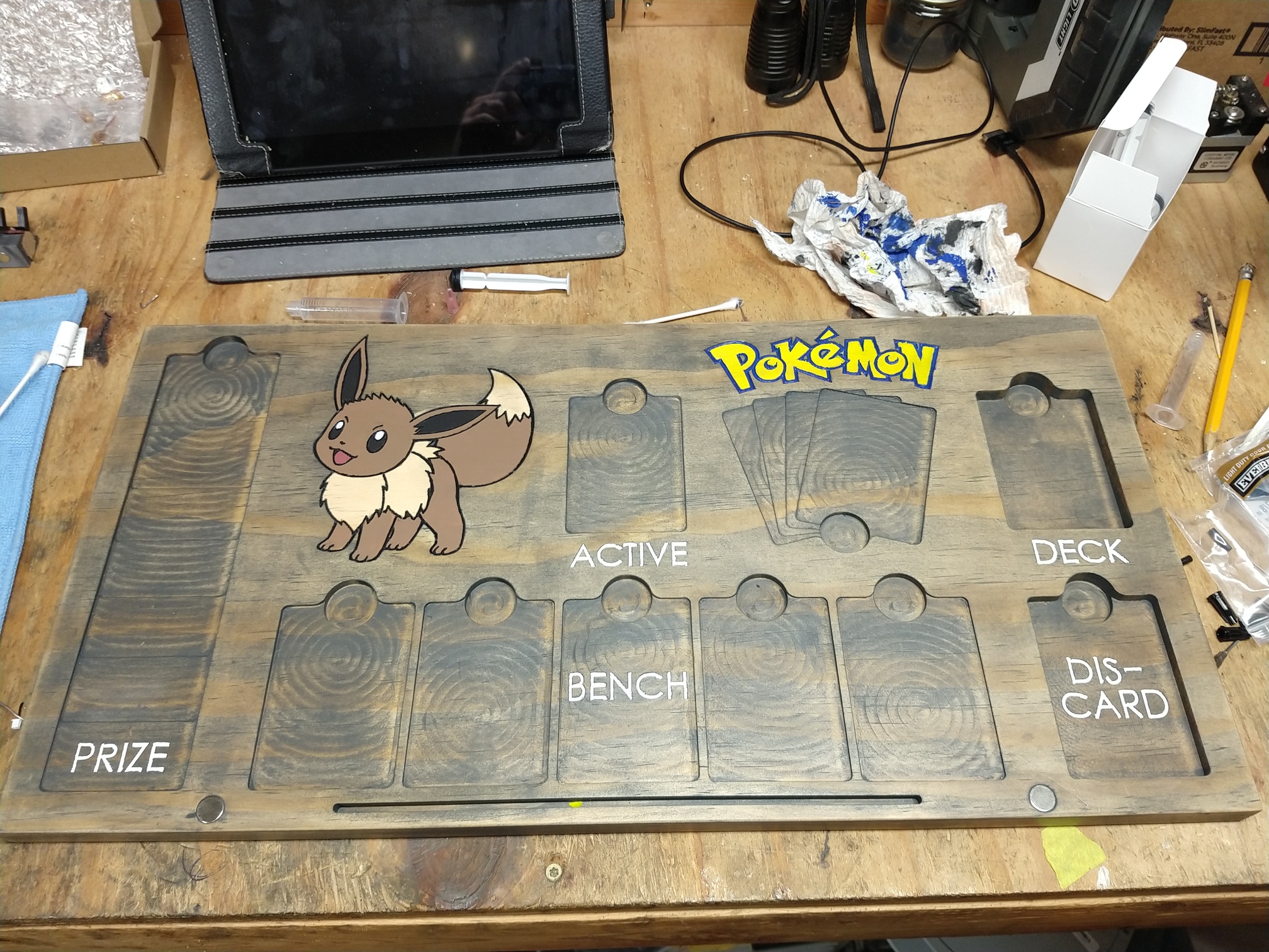
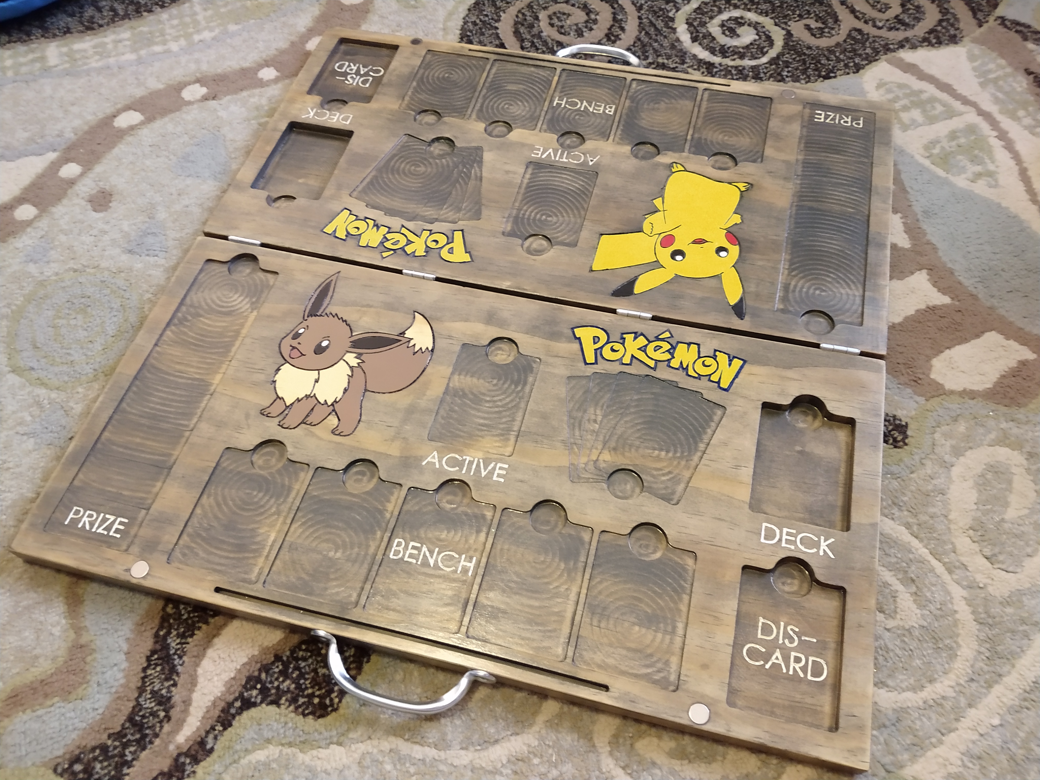
This is my biggest cut yet, based on size and run-time…Its a card game board for my son as a bday present. There will be a second side, which gets connected to this one with a hinge to fold up when not in use. It will definitely get some stain and tung oil, and i am considering coloring the character and the logo with paint. Its not perfect, some of the round pockets are oblonged due to having to re-mount the part and enlarge the features. Even with a hard origin on the table, the board was skewed slightly, and the error projected across 22". Side 2 ought to go smoother with lessons learned.
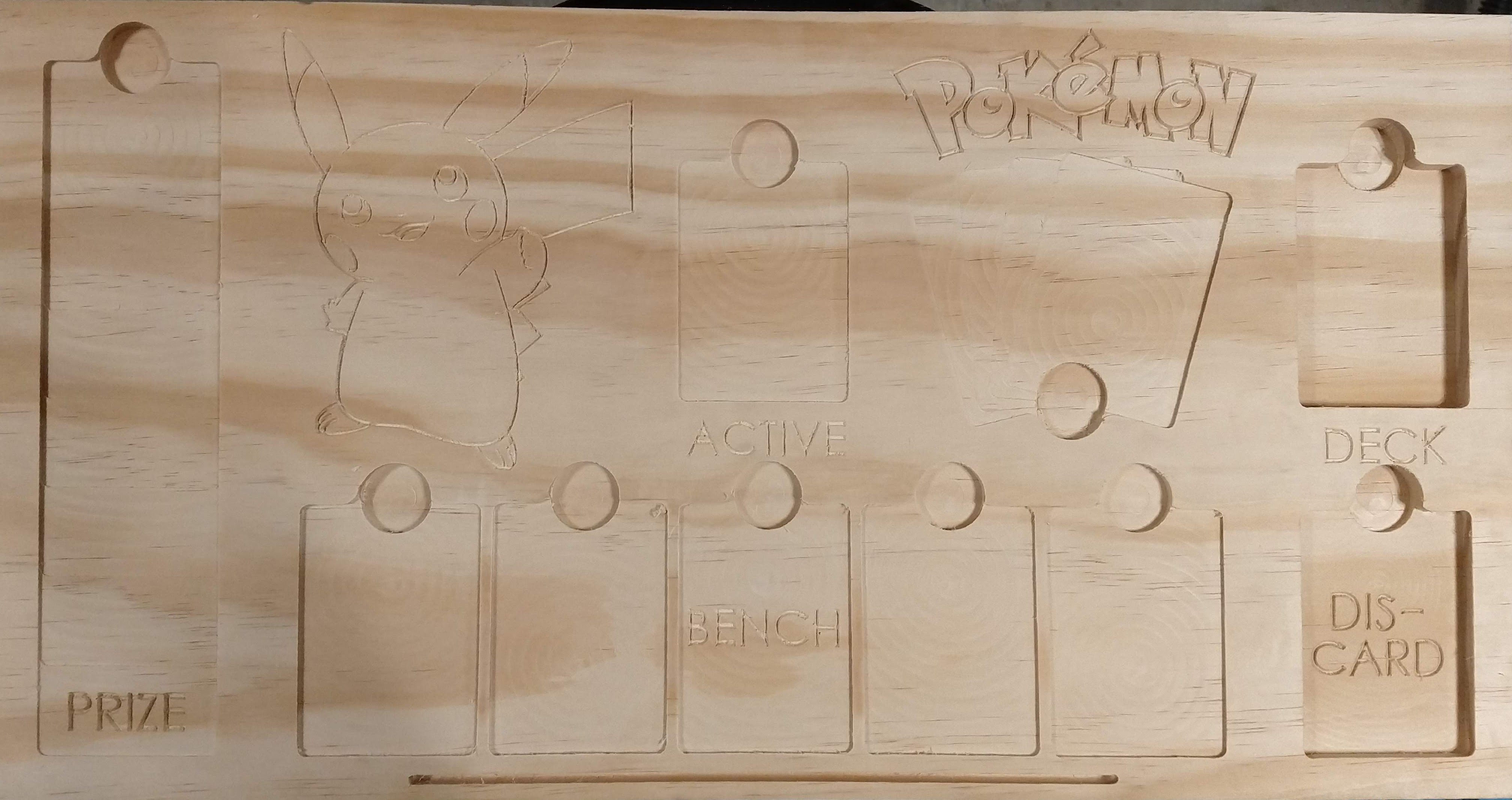
That looks great. I am sure some finish will bring out a lot more contrast. If you do end up painting, unfinished wood can soak it up in the fibers. Which will look like it bleeds a bit. There have been some discussions here about it. I would definitely put whatever stain and finish on first and then try the paint, so the wood will soak less up. I don’t know the different finishes well enough to know if tung oil is strong enough to keep the paint off the wood. Might be worth it to so a quick test in a piece of scrap.
Thanks for the advice, Jeff, i will keep that in mind.
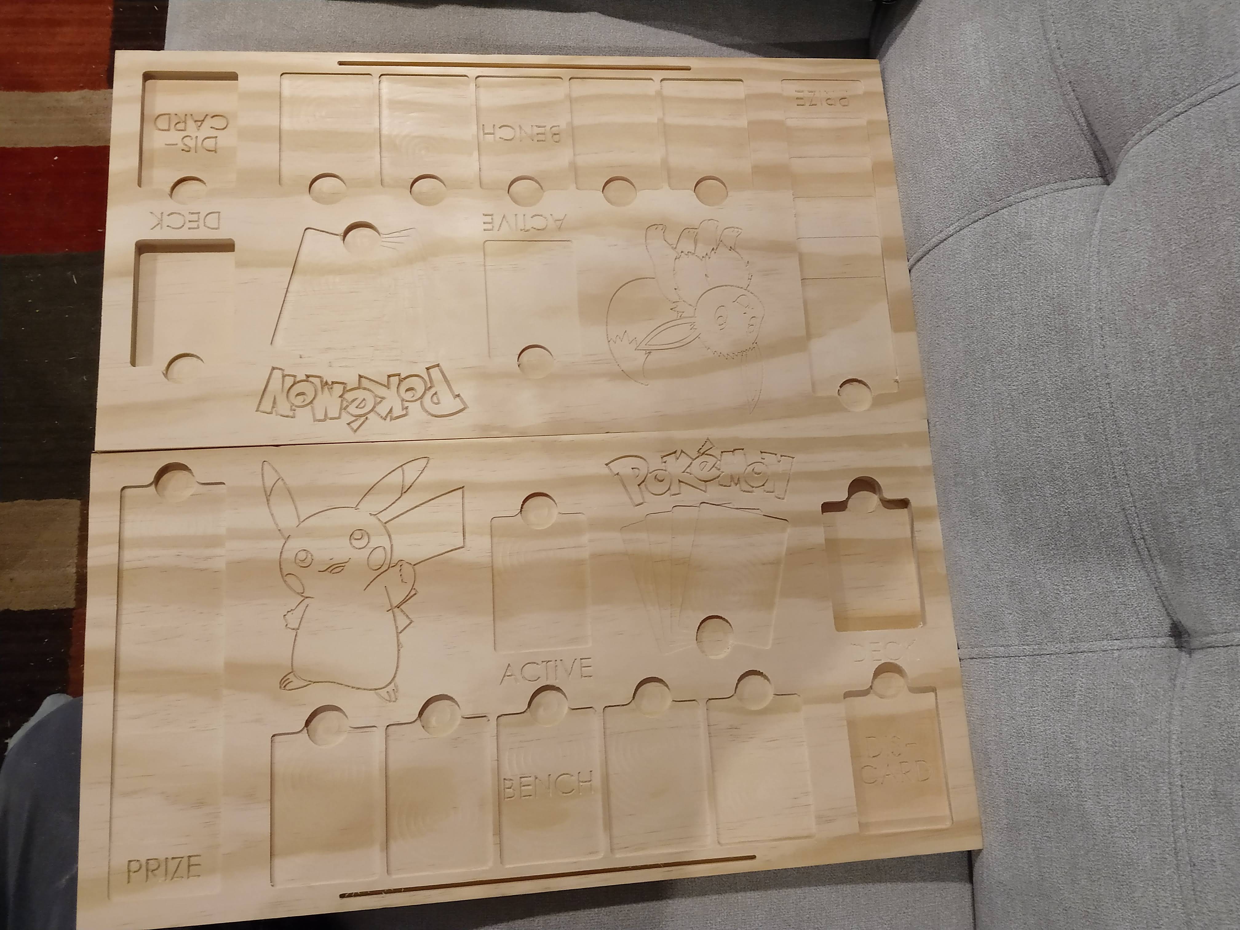
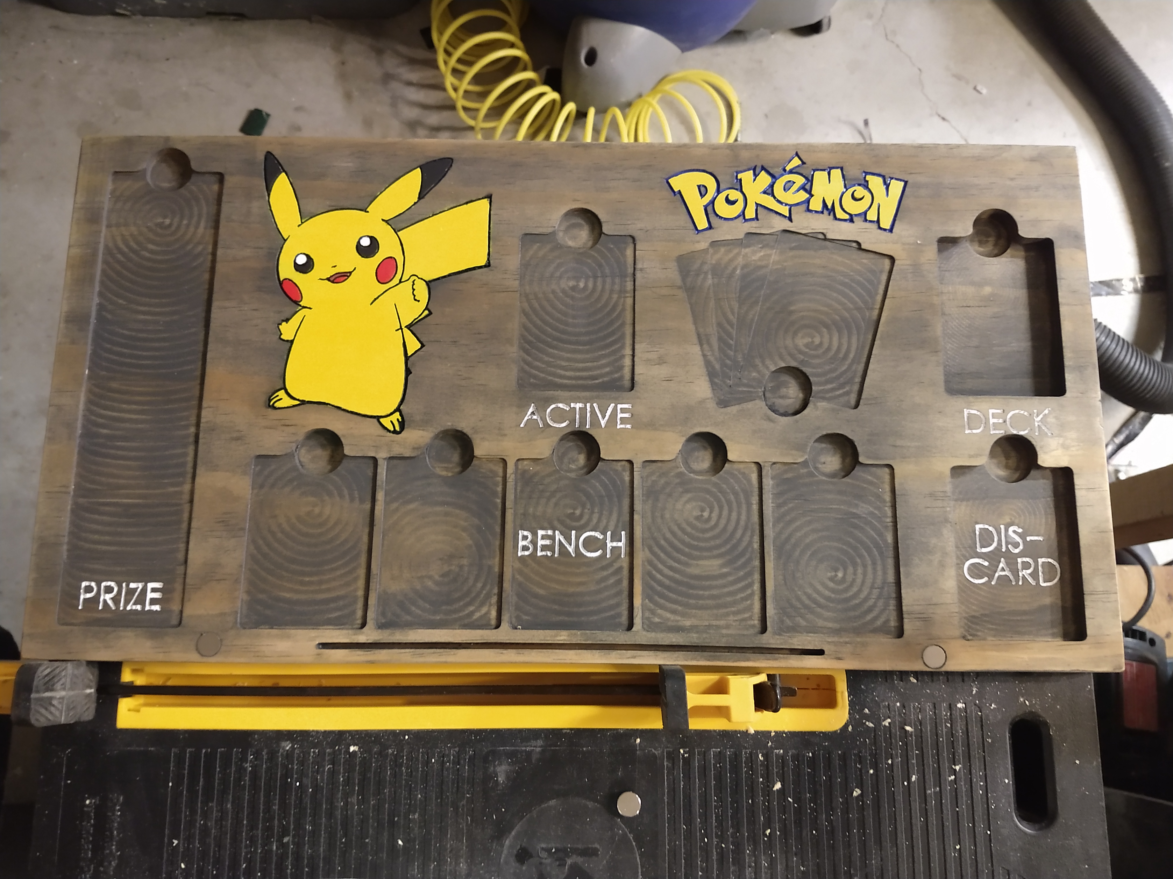
Side 2 went perfectly, all kinks sorted out. Just a little chatter in the deeper pockets during full depth adaptive clearing; i was taking a big bite i guess, even for pine. That and my machine is not cutting square. At this point, not really sure if the hard origin is out of square to the machine, or the X Y rails are out of square to eachother…maybe a little of both.
On this job, I did not cut all 4 sides. I laid 1x12" stock up to the hard stops on my table (an aluminum “L” bolted to the table), then just cut the board to length with a slotting toolpath. Even if the XY were perfect, if the board was askew to the machine I would get a slight trapezoid.
I do not have dual endstops (which in hindsight, I should have done). I use a VERY beefy machinist square on the rails during my power on procedure. I actually lay the square on a 2x4 to raise it up, then clamp the x and y rails to the square before powering on the motors. This seems to get me close.
These boards are also 22" long, so my error is projected, and my machine is 2’ x 4’ (I would hate to see the error over a 4 foot cut!). I am probably in lowrider territory, I knew that when I started, but I resolved to live with the shortcomings. Luckily for this project perfect square is not critical. Since the two sides are both out in the same direction, they will fold up flush to eachother and no one will be the wiser!
Oh yeah…that’s the stuff. I love it when a plan comes together!
Tomorrow we poly. Then assemble. Delivery to the “customer” is Saturday!
The card table is done, will get some pictures tomorrow after party time.
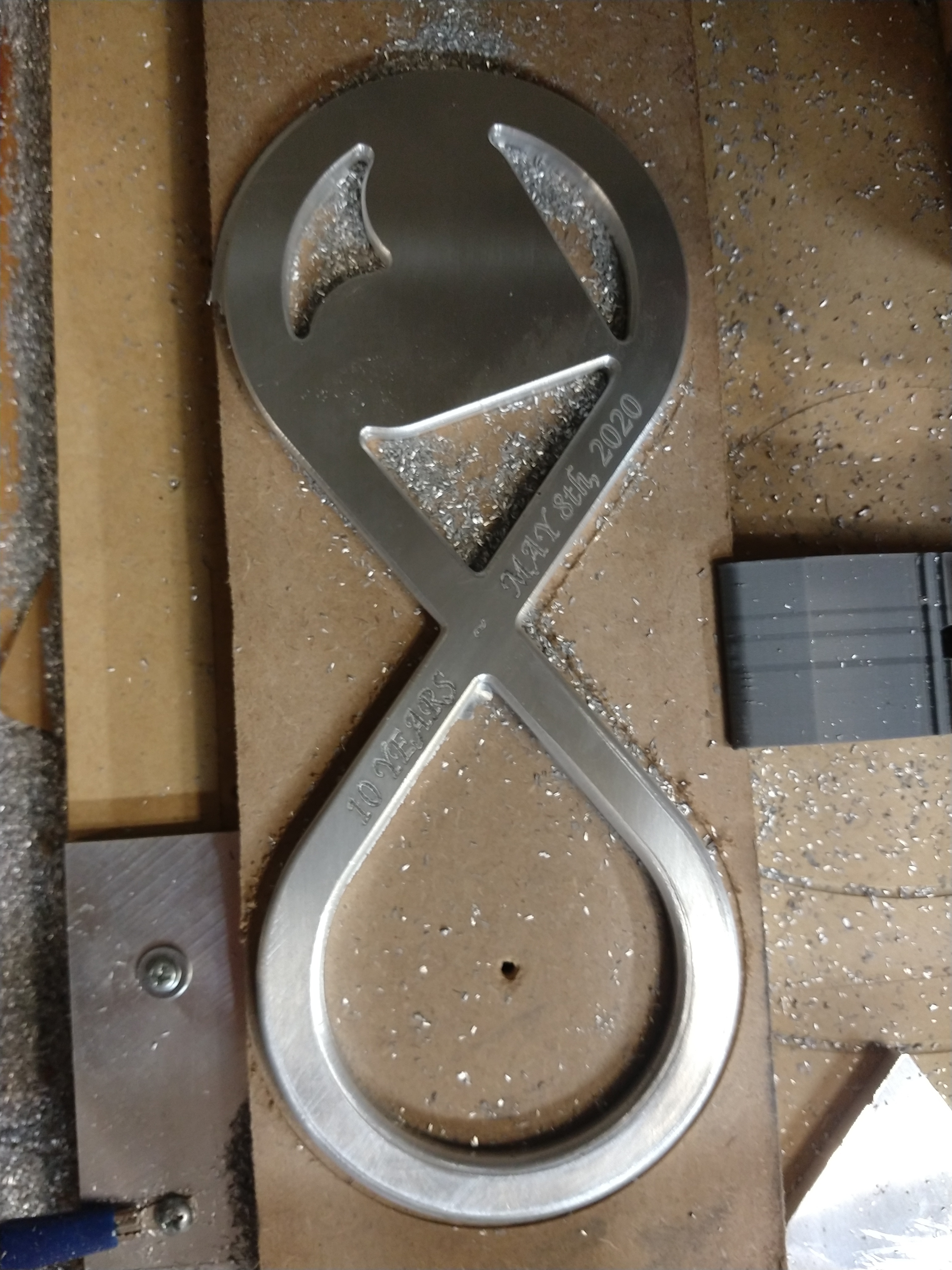
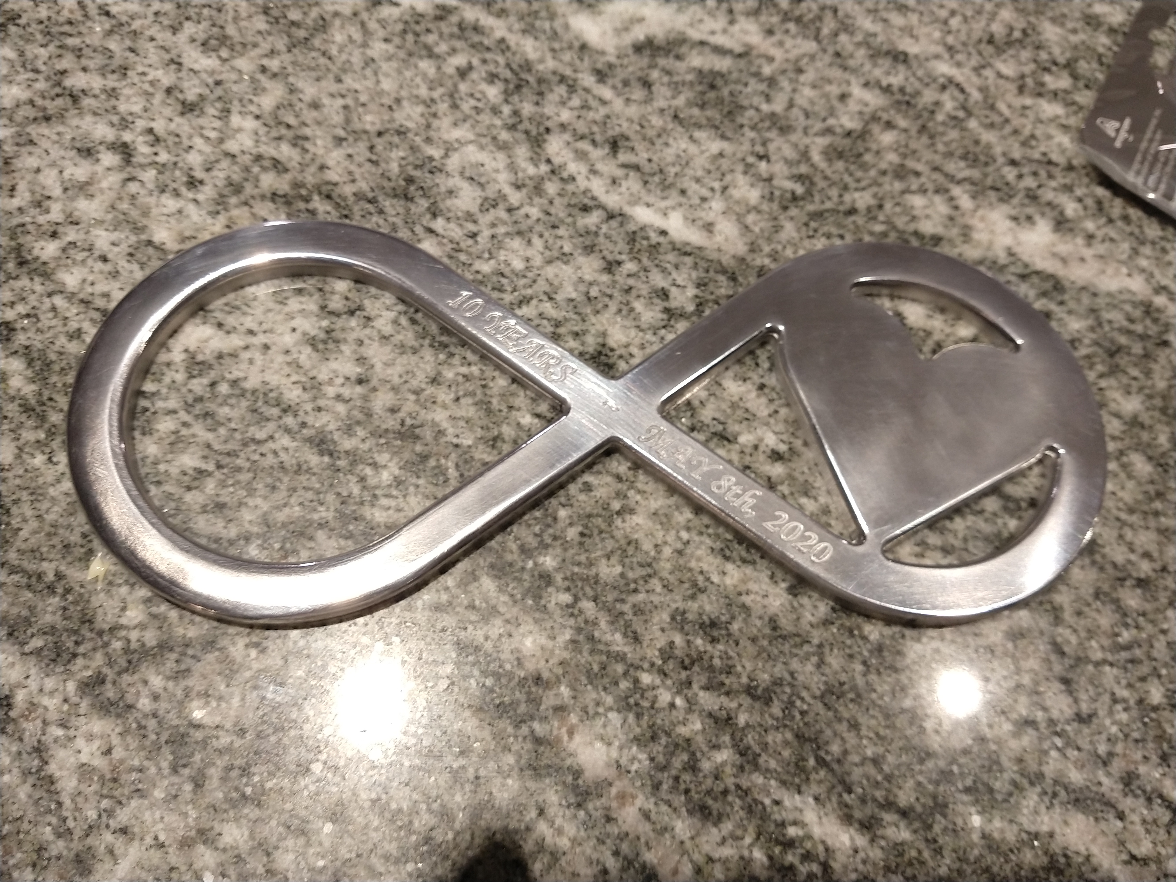
Switching gears, this was supposed to be an anniversary gift back in may, but got put on the back burner. Apparently 10 years is the aluminum anniversary
After some sanding, filing, scotch brite, and polish:
I’d like to polish it more. The job itself went ok. My machine is big and chatters a lot on heavy cuts. I also burnt up one end mill going too aggressive with an adaptive clear. 10% stepover at .25 doc was too much, had to cut it in half then everything was pretty happy.
Slotting was done at .015 doc, 450mm/min, machine was very happy here.
Finally I have to plane my table someday; had some inconsistencies in the roundover cut.
I plan to mount this on a nice piece of oak, stain and poly

Solid projects! Thanks for sharing.
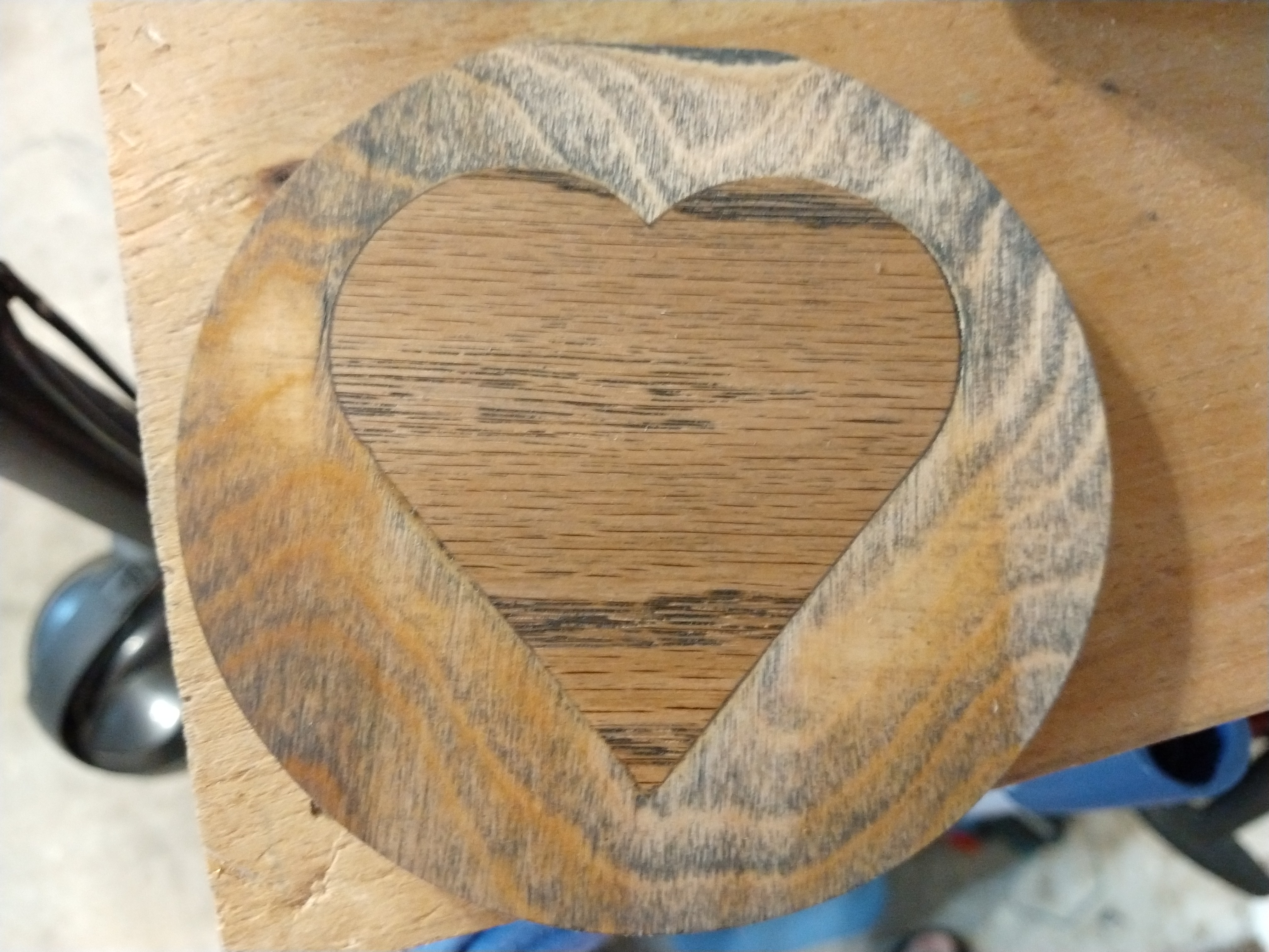
My first test of an inlay. The base was plywood, and I sanded through the veneer inadvertently. This was made out of scrap just for process development purposes.
The fit was ok, even though I made some mistakes. I need to make deeper bevels next time, and mind the radii on interior corners. Enough glue and clamping covered up some fit issues.
All in all, it’s a solid process that I can expand on, so I’m happy!
I don’t think anyone could complain about that fit, good job.
Thanks! That means something coming from “the maker” lol. It’s amazing that (and I mean NO offense) that “pipes and plastic” can achieve this level of accuracy. Speaking of which…

Aluminum and I are coming to an understanding. This was cut with a 2mm single flute, from 1/8" hardware store architectural “bubble gum” aluminum.
I predrilled with the cnc, then finish drilled and tapped by hand. For the bearing, it took me a few tries, but I found that a line to line fit was perfect, but I had to do 4 finish passes to get the size right: 1 removing .005" then three zero thickness passes to clean up and account for deflection. Once I did that the light press was perfect. This is another part for the model engine project.