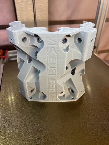
I did have to file the belt tensioners a bit like Ryan said but it looks like you’re good to go. Also some of the bolt holes were a little tight but it also wasn’t a big deal. I used partially threaded hardware so it may be a combination of that and my holes printing a little on the small side.
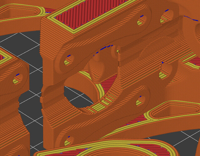
@karltinsly Oh, I forgot that I did have an issue printing the trucks. There is a thinner web of material under where the steppers are mounted that didn’t print well at the larger layer height so you might want to keep an eye on that area. But it looks like your printer may be dialed in a little better than mine at the time so hopefully you don’t have any issues.
@Bigchepin I’m printing the trucks now - all 4 plus some other stuff in a 22 hour print. I did take a closer look at the slicer and I see the area you’re talking about. If I had seen your message before I started I might have been able to play with the setting some to clean them up, but they might be fine anyway. The slice looks like it’s missing some perimeters, but there are no holes that I can see, so maybe they’ll be okay. Thanks for pointing that out - I’ll be able to see those when the print is halfway through - if they look bad I can stop at that point and save at least some time and filament - but honestly, I think they’ll be okay.
Dang. Fingers crossed! 
Everything finished printing just fine. All the parts are in. I just finished dismantling my old MPCNC and I’m ready to start reassembling my new Primo!
Quick question - the gantry pipes on my old MPCNC are the same size as the outside rails, but the calculator shows them to be shorter. Do I need to cut my gantry pipes down?
Here’s another surprise I’ve run into - the build starts with screwing down the feet? Those were the last things I fixed in place on my original MPCNC. Since I’m replacing 100% of the parts, I’ll follow the new directions - I was just surprised. Of course, it could be that the original MPCNC build started with the feet and I just ignored it LOL
BTW I love how Ryan has steadily reduced the number of parts in the Z axis - the original had 10 or 12 relatively spindly parts all bolted together. This new version is an absolute unit!
Smol progress report: feet are squared and locked down (OMG there has to be an easier way!), trucks are built and tensioned, with clamps mounted. Should be able to get back to it tomorrow afternoon.
In case there’s anyone looking for information about reusing old MPCNC parts on a Primo (my original topic) - you will need to buy the 5/16 x 1.5 inch (the M8 equivalent) - the bolts on the old MPCNC and on the burly are 1.25 inches will not engage the lock nuts fully. Also, you will need the M5 nuts and lock nuts - there are no equivalents on the older design. Also, you will need a lead screw. I have some from decommisioned printers but you’ll need to buy one if you don’t have one already. Since I’m building the conduit version, I can reuse all my rails. You might have to cut the gantry pipes down a little - they are apparently not the same size as the rails anymore.
Oh, and note that the x and y motors are now mounted vertically, with the belt “arch” running horizontally outwards. I had to resize my machine because the physical space where my MPCNC lives was just big enough to clear the old trucks and motors. The new motors stick out a little more - enough that they (probably) wouldn’t clear.
You can leave the rails sticking out a bit if you would like, no harm there.
At first, I think I was hoping the bolts would do all the work, but turns out you can just add plastic a lot easier!
Sorry, I thought it was the same. Looking at it though, it very well could be a slightly larger overall footprint.
I hope everything feels noticeably better at this point for you.
Oh, overall everything is great - I’m just documenting things I’ve encountered so if someone else comes across this thread, they can see some of the issues I encountered on this upgrade.
Oh hey, I’ve been looking through the docs and I can’t find any specs or links for the end stops. The ones I have don’t fit - can you point me to the right ones?
Never mind - I made some measurements and ordered some that will fit.
Both versions I have in the shop fit.
Okay, thanks!
Okay, some new questions - I’ve built the core, and when I test fit a piece of rail (with no nuts on the tension bolts), it looks like it touches all the bearings and “feels good” as the docs say it should. But it also moves quite a bit if I wiggle it around. How much wiggle is allowable?
Also, I did not drill out the 5/16 holes for the bolts, so the bolts are threading themselves into the plastice of both the core and the clamps - should I drill those out to get better adjustability and fit? Seems like tightening the bolts and nuts would have more effect if the bolts were moving freely in the holes, but I wanted to check before drilling the holes out.
Can you elaborate a bit more on that? Are you pushing on the core and the tubing is causing the trucks to move around or something else?
Are the threads really biting or will the bolts eventually free spin if you add a little extra torque (not adding too much torque that you start hearing layer cracking)? Multiple threaded parts will give you issues. I had a few holes that were a little too small on mine so I ended up drilling the holes out lightly if I was not able to strip the threads (that were formed in the plastic) by hand. When I say lightly I mean zip the bit in and out not pausing to increase the hole too much.
No I haven’t mounted the core on the gantry rails yet. Just took a spare length of conduit and slid it into each side of the core to test the fit as directed in the docs. So the core is sitting on the bench, and I can slide the rail in and out smoothly. But if I try and wiggle it side to side, there is some movement.
The bolts bind unless turned with a tool. I could turn them enough to strip the plastic, but I haven’t because I didn’t want to crush the risers. I think I’ll drill out the holes. They’re only a tiny bit undersized, but I’m sure the design expects for the bolts to be able to pass through them without binding.
Thanks for the input!
I wouldn’t. If there are any that need to turn, just strip them first. Leave the material there. Drilling removes material. It is plastic and it does deform so the more you leave there the better.
If it is touching all three bearings it is perfect, it should not be able to wiggle. If you are referring to the core clamps, make sure both are on that rail before you test anything. If you mean the Z axis, same deal both rails are needed.
Okay, thanks Ryan. I won’t drill them out. I did turn them a bit without holding the nuts to make sure they were turning freely.
I’m still concerned about looseness. Maybe I should make a little video to show how much play I’m seeing. I’ll see if I can’t do that shortly.
I haven’t built a primo, so take this with a grain of salt. But I wouldn’t worry too much until you have it more complete. It isn’t rigid until the motors are powered.
How important is it that the z axis motor coupler be flexible? I have the flexible one from the store, but my old build had a solid brass coupler that did not flex - any thoughts on which would be better?
If your alignment is perfect and your screws are extremely straight, no big deal. Try out what you have and if it binds get some flexy ones.

