The Ortur 10w laser is pretty new, so I don’t know if anyone here will know the answer, but I’m asking around a few places, hoping someone somewhere will know.
The laser comes with an “adapter board”, which takes a 12/24v connection, ground, and PWM signals in multiple places - it says on the board that only one input is allowed. There are also multiple outputs, but the instructions say that the 10w laser connects to the 6 pin plug marked Output B. The pins on that output show two pins with 24v, two with ground, and a PWM pin. Other than the ins and outs, there’s a fuse, a couple of schottky diodes, some resistors and LEDs. Here’s what it looks like:
Because this laser is designed to bolt on to Ortur and other laser machines - it comes with a mounting plate with screw holes marked for different machines like D1, A5 Pro, and X7 Pro - I believe that the only thing this adapter board does is help to make the laser basically plug and play for these other machines. I’ve watched some install videos, and they say “locate plug X, disconnect it, plug it into the adapter board, and then plug the new laser cable into the adapter board.” The multiple outputs probably let them use it with other lasers they make.
So my question is this - I already have 24v, ground, and the PWM signal running to a connector on my Z axis, so I shouldn’t need the adapter, right? I’ve created my own adapter that connects 24v to the two pins that need it, ground to the two pins that need it, and the PWM signal . I haven’t tried hooking it up and turning it on yet though - I wanted to see if anyone knows of any reason why I can’t do what I’m describing? Does the adapter board actually do more than what I think it does?
Based on thrashing around trying to figure lasers out several years ago, I have reason to believe (but no proof) that some of these companion boards provide some sort of voltage mapping where the board accept PWM in the 3V to 12V range, and that signal would be mapped to say 5V for the laser. Ortur is one of the heavy-weight companies for diode lasers, so it is likely you can get an answer directly from them.
Why do you have your PWM input to the laser going to your Z axis?
IMHO that adapter board is just as you suggest, it only provides different plug options for different set ups. The two diodes provide a modicum of reverse connection protection but little else.
Do you have a scope? You could compare the pwm going in to the pwm coming out. It should be high impedance, so if the voltage doesn’t change. Then Mike is right. If it changes voltages (significantly, like 5V to 3V), then Robert is right. (It sounds like I’m pitting them against each other, but they are both experts with competing ideas).
Thanks, Robert! That’s a good idea - I have emailed Ortur support with the question. I also discussed with Myles at NewTechCreative, which is where I first heard about this 10w laser. Hopefully Ortur will get back to me quickly and confirm.
I actually do have a scope - I built a little handheld one from a kit a few years ago. I would have to figure out how to actually use it though LOL. I would also need to hook up the adapter board to power and figure out how to run a PWM signal through it. All of which I can do, if necessary, but I hope I can get the answer without having to do all that. Good idea, though - I’ll keep it in mind as a possible avenue of research.
Here a what Ortur support had to say (quick response - nice!):
The adapter board does nothing else but being a “converter” for wiring and filter 12v and 24v
if you can supply the laser 24v and pwm you don’t need anything else
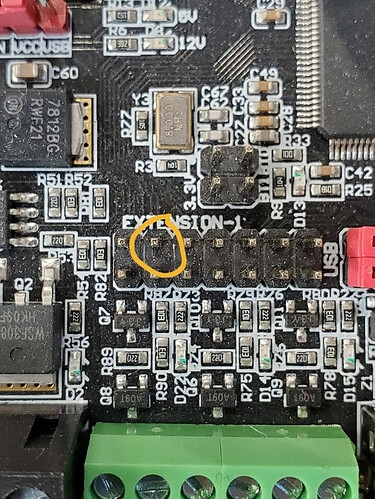
Can someone verify that the PWM pin on the SKR pro is this one (found in an older thread - just want to make sure it’s still accurate):
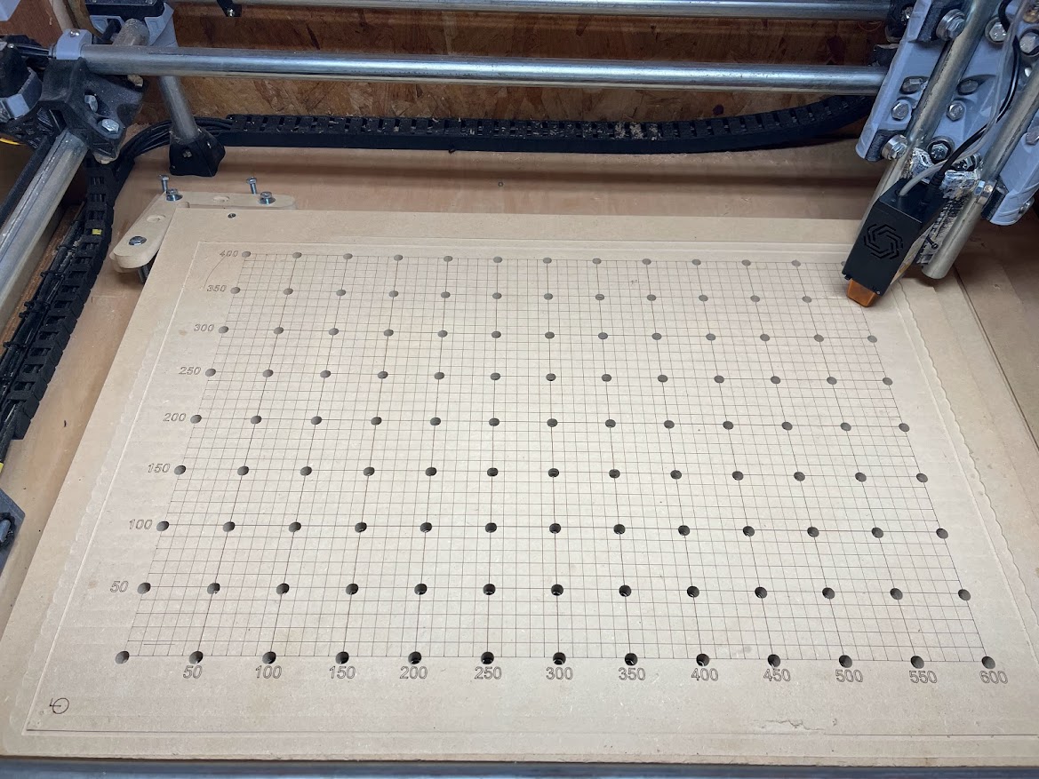
Update: all hooked up and working fine using the laser power and laser toggle on the menu to test. Time to set up some test burns!
What are people using for work surfaces with their lasers? I’ve seen honeycomb on Amazon, and I saw a pic where someone had their work resting on a “bed of nails” made using rivets. What are y’all using?
Directly on the spoil board, I have a piece of sheet metal. On top of the sheet metal, I have an aluminum honeycomb. I went cheap and purchased the honeycomb without a frame, but if I had it to do over again, I’d definitely get one with a frame.
After I had my laser setup working, I ran across metal lath at Home Depot. It looked like it would do the job, and cheap at only $20 for a 27" x 96" piece.
You may want to consider your hold down strategy. Magnets and pins are common solutions for commercial machines, but neither will work with aluminum honeycomb. I primarily use pieces of sheet metal and lead ingots.
If you are going to do a bunch of cutting, then air assist will make a big difference. That is one of the main values of a honeycomb. If you are not going to use air assist, then I would consider a honeycomb optional.
Congrats on getting your laser working. I get a lot of joy out of mine, and I’ve been using it daily lately.
I have box with honeycomb for support, hooked up to my dust collector to remove fumes. The problem is such a vent box has to have height to work (mine has a 6" z so can fit the 3" tall box under the laser, with plenty of room left for materials).
I’ve also used wood grids and bed of nails. Both worked OK, the wood grid of course needing occasional replacement. Both however don’t work as well for very small parts… sometimes a cutoff would tilt and not fall through, catching fire etc. 1/4" pitch alum honeycomb fully supports even very small cutoffs, so you get a higher success rate with detailed parts.
To add to this… some of the higher powered lasers can do appreciable damage to whatever is underneath. The bottom of my box is lined with sheet alum to handle a powerful neje doide… laser just bounces off so the MDF underneath will last forever (also much safer WRT fires). It isn’t a necessary feature especially with lower powered lasers, but something to consider if you’re making ‘your last laser support’.
I went ahead and ordered a honeycomb board from Amazon.
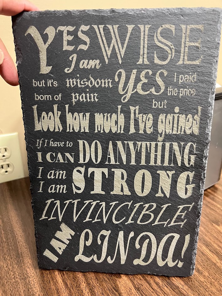
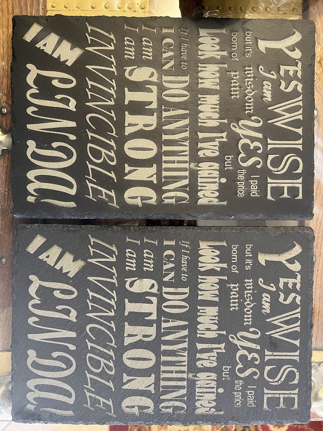
I ran a material test in light burn on a piece of scrap plywood, then ran one on the back of a slate charcuterie board. I’m now etching my first slate project - can’t wait to see what it looks like tomorrow!
Came out pretty good! I might make another one, but darken the slate with mineral oil first, to heighten the contrast. Will also give me the chance to test “erasing” etched slate.
I made this for my wife, who has been battling cancer for over a year now.
OK - so I took the plunge to try and adapt this laser to my machine. I think I understand the principle of bringing the pwm off a fan pin. But I did have a couple of questions.
Can I just cut the connector off the included cable and lengthen it? Will there be noise issues that affect the laser? Suppose I could try to mount the board close, but then the pwm still must run from the control box, so I don’t think it makes a difference?
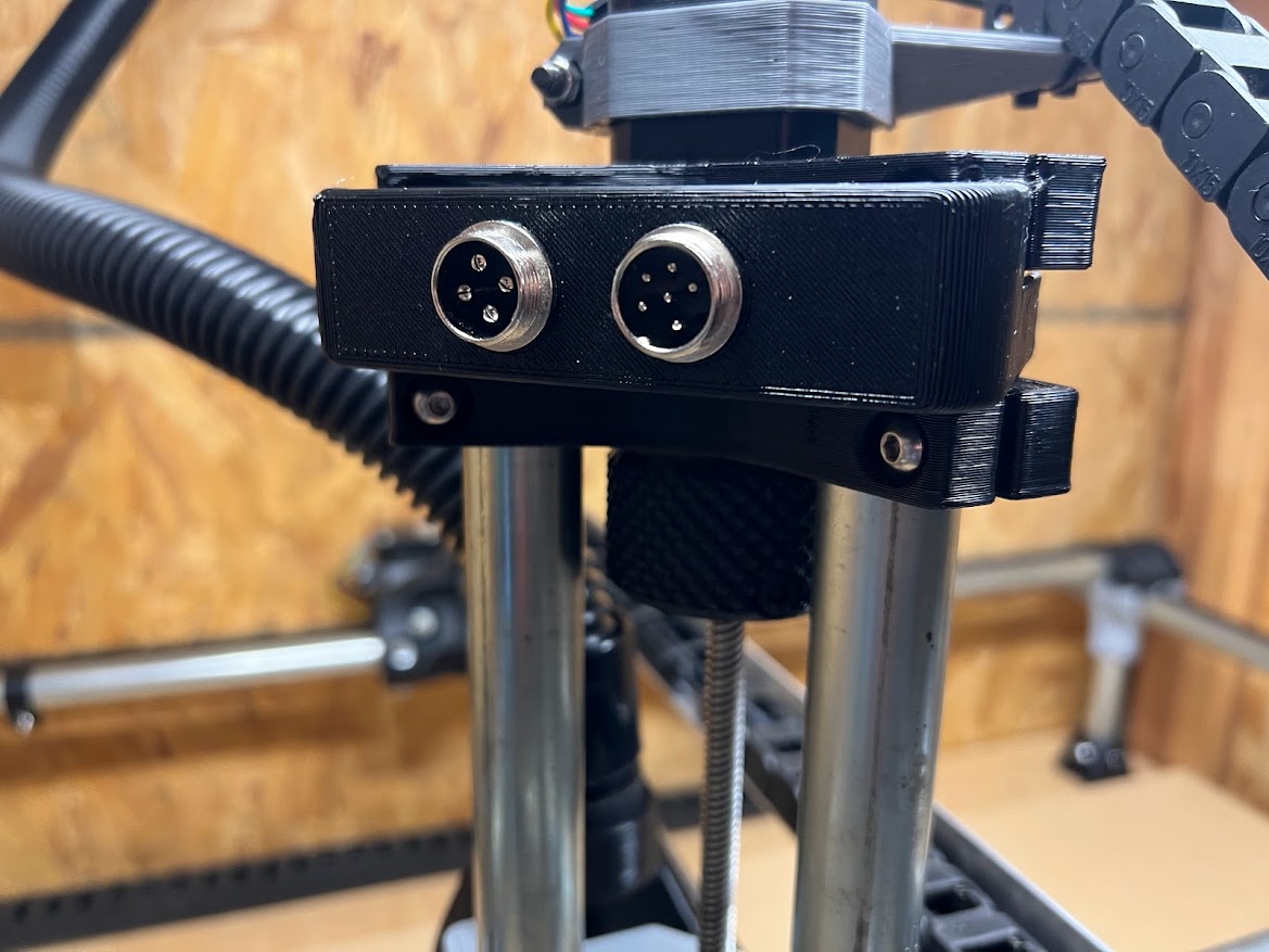
With your xlr adapter, you use 2 pins on the 4 pin for load/hot for the router? Are the ratings for those adapters per pin or are they for the whole connector total? Do you happen to have a link/record of the type you’ve got that works?
Thanks for any guidance you might offer. Your results look awesome.
edit:
Since there haven’t been any replies yet I wanted to add one more question. Do you run your air assist line through your cable management? The tube seems flimsy enough that it may kink or be crushed in a cable chain or even tape measure trick. Reduced diameter would mean much less air flow, which defeats the purpose.