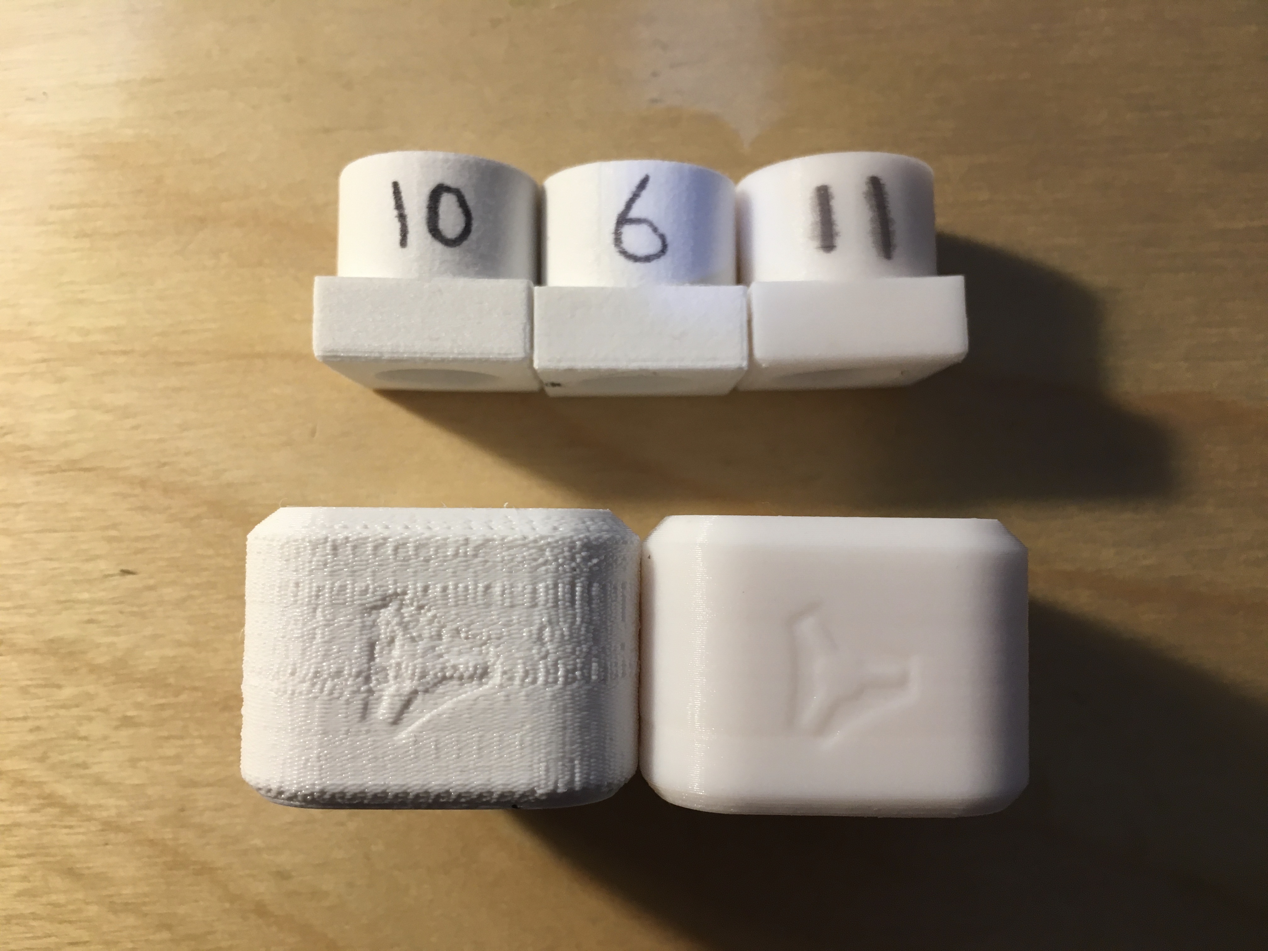
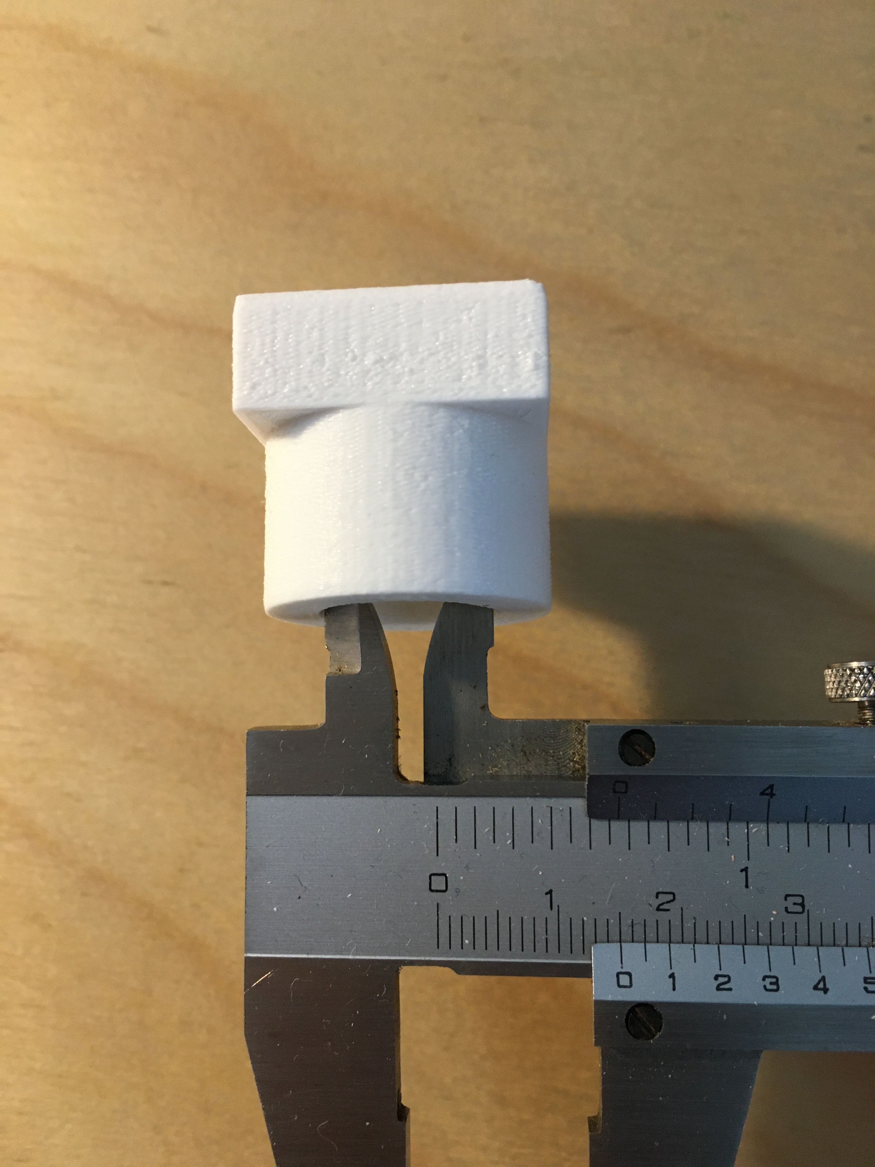
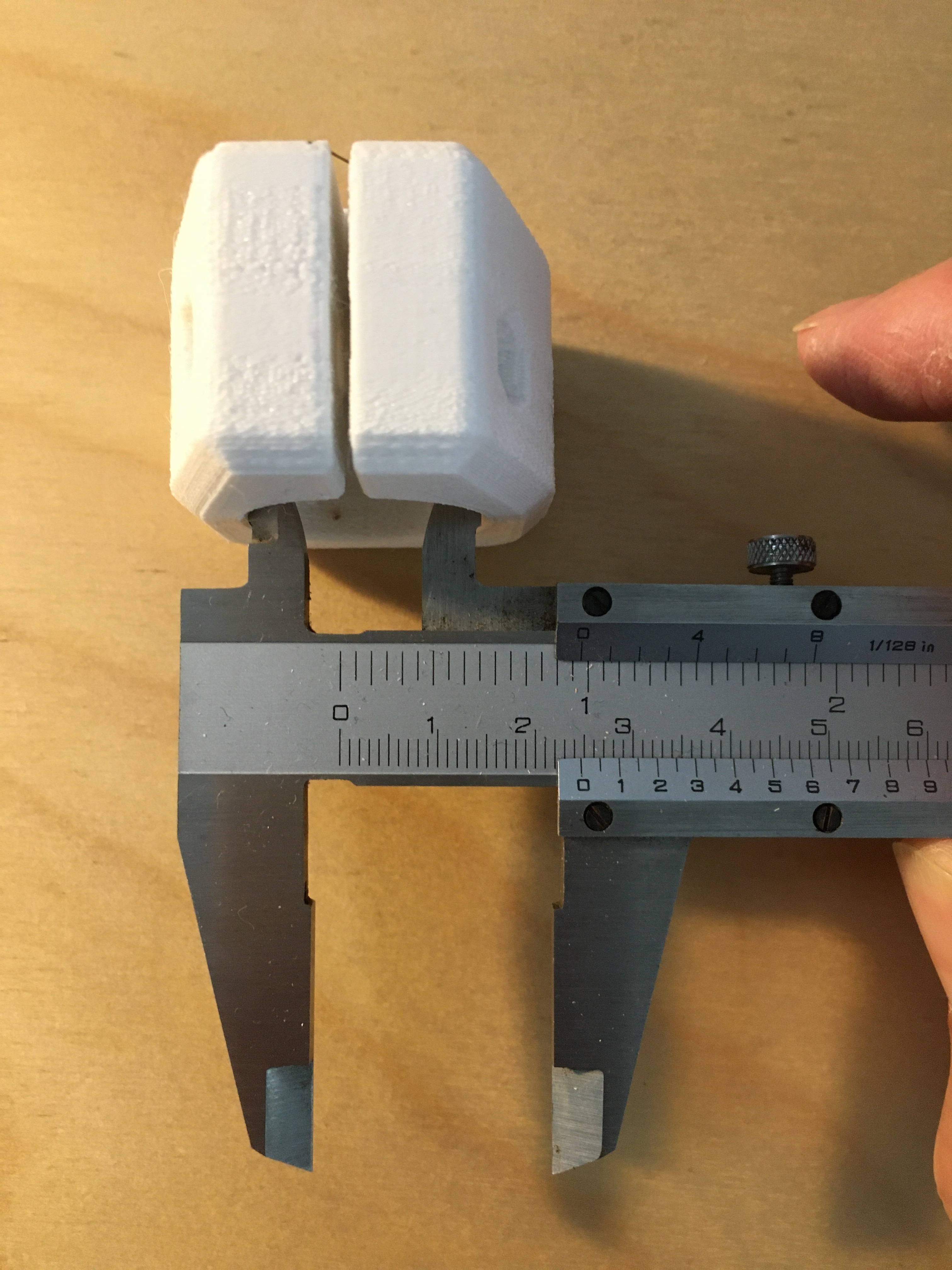
I had all the parts for the very first edition of the 25mm MPCNC printed by a friend, but I’ve not been able to get hold of 25mm tubing where I am and some of the parts needed reprinting anyway as they had warped so I’m right at the beginning of trying to get going with a Primo build. I’m having a strange issue printing the corner leg locks and feet. I thought I had my printer dialled in pretty tight. The dimensions in my test print agree to within .05 mm or less. Here are some snaps of my test print. As you can see the dims look right:
Should be 25mm
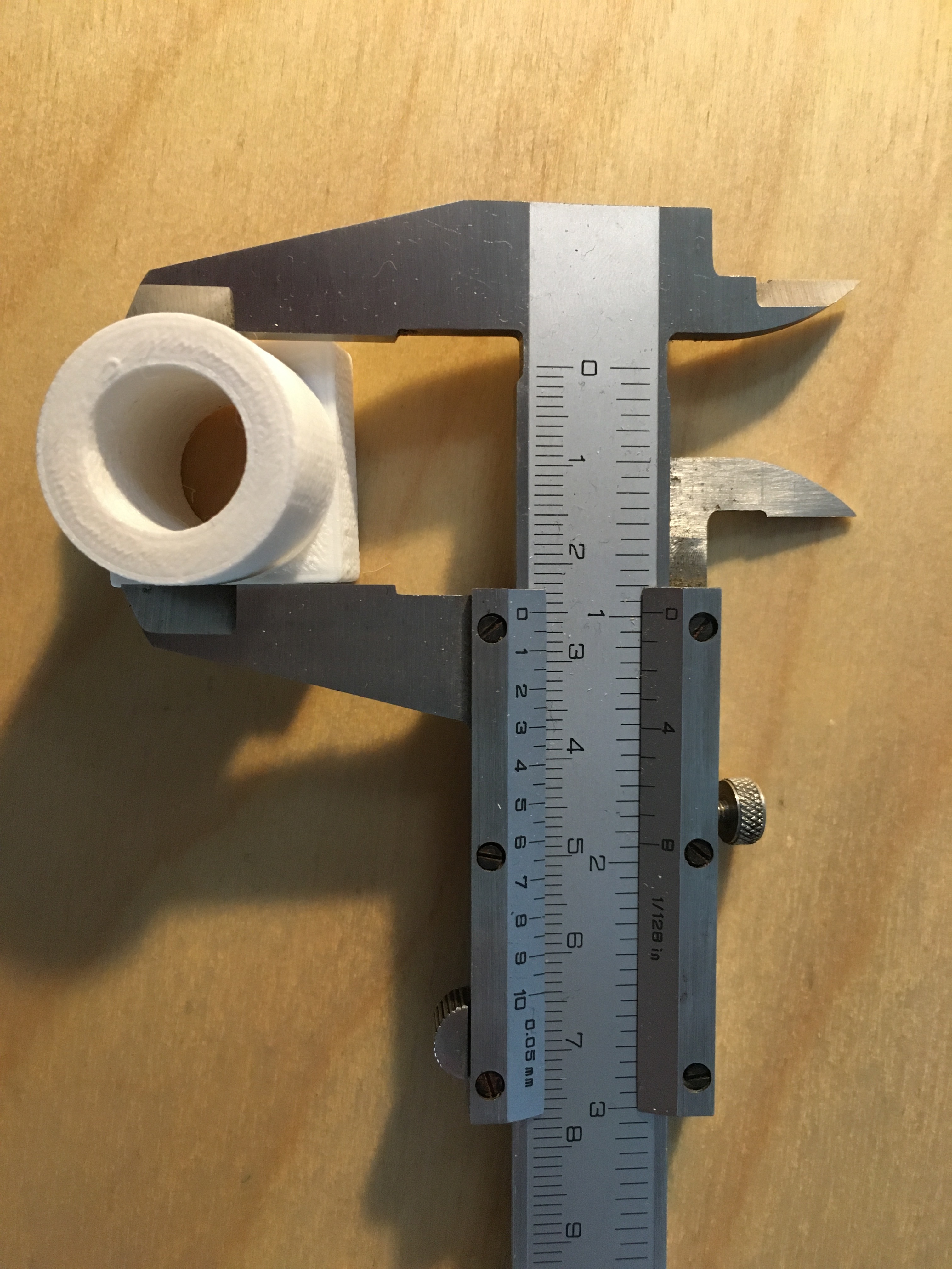
But when I print the corner leg locks using the exact same slicer settings the internal diameter is about 1mm too small and the print looks a lot rougher.
Should be 25.7mm but is 24.7mm
.
I opened the stl file in my cad and checked and the dimension I should be getting is 25.7mm.
So it seems that whatever slicer settings I’m using are not optimal for the MPCNC prints. Has anyone else encountered an issue like this? I’m using the Cura slicer in Cura 4.7.1 with a weird kit built vellman k8400 3d printer. One thing I noticed in my calibration tests is that I seem to get better quality prints if I print the walls first and then the infill, but Cura notes that this can cause problems with overhanging chamfers. Do you think there will be issues if I print walls first?
I’m quite new to getting accurate prints out of my printer, so this is maybe not the right place to ask this question if not, could someone could point me to a good 3d printing forum?
All of the mpcnc parts are designed to print without support, so if you have decent part cooling fans, perimeter first printing should be fine. I’ve always used perimeter first printing with everything i print and have had no issues.
There is a horizontal hole adjustment in cura, but I can’t think of any other settings that would steal 1mm from the geometry. Same settings for both parts?
Yep, I’m using the horizontal expansion adjustment to get it spot on and I haven’t touched this between test prints and MPCNC prints. I’ve done about 20 calibration prints on a 25mm sized object which I’ve gradually evolved from a cube as I noticed that some settings make round surfaces look worse without affecting the surfaces that are square to the printer axes and as you say you have to adjust the hole horizontal expansion as well as the general horizontal expansion. Every time I change a setting or two I create a copy of the config in Cura and then write the number on the test print. I thought I had it set up pretty sweet… What speeds are you printing at? My nicest looking and most accurate print so far has been printed at 60mm/s with walls printed first. Is that fast?
I don’t think that’s too fast for pla. I print my infill at 100 and walls at 40-50.
Still, really bizarre that the same settings on two parts so close in size would be so far off. Makes me wonder if one model is more…refined than the other.
Aside from that, i don’t know what to say about the accuracy of your machine other than start at the beginning with the calibration. Make sure the steppers move exactly as far as you tell them to with a dial indicator or something strapped to the hot end and pointing at a rule (@dkj4linux likes bamboo skewers). Using printed objects to measure distance introduces error from the amount of plastic extruded…too much or too little can make your dimensions to large or too small.
Good luck figuring this out.
So I used up the last of my white Velleman PLA reel and put a new Sunlu one in. Test print 11 is essentially the same settings as test print 6. But as you can see just changing the PLA has made a vast difference in quality. Also Sunlu claim that they wind their PLA on so you don’t get crossovers that jam the reel. Woohoo!
I thought the jubblyness of the surface on the old prints might be making up the 1mm… The test print in the new PLA is absolutely spot on, but my leg lock hole is still 0.6mm too small. Bah!
Screw it. I’m just going to bash it onto the leg tube with a hammer, print some more bits and hope its just this part that’s printing weird. Wish me luck.
Well that didn’t work. 0.6mm too small is too tight. Back to the drawing board. It must be something to do with the slicer settings because the test print agrees with the my test print CAD model to within 0.05mm. The only thing I can think of is that the slicer doesn’t see the leg lock hole as a hole because it has a slot cut in it so I might have to set the horizontal expansion to be -0.6mm and put up with the overall outside dimension being too small which wouldn’t be critical on this part. Doesn’t seem like the right solution though.
How close are your prints without this adjustment? I always worry these “fudge factors” end up masking issues that are better solved with careful calibration. For me, I tend to end up with really good mechanical motion accuracy for Z, Y and Z on macines I build but initial extruder calibrations almost always end up with me pushing too much plastic, ending in parts that are off of spec (and don’t look particularly good). On my latest machine, I had to dial down the vRef on the extruder stepper to eliminate moire/pulsing before I could get to repeatable, reliable extrusion dimensions, then had to re-dial in my extrusion multiplier.
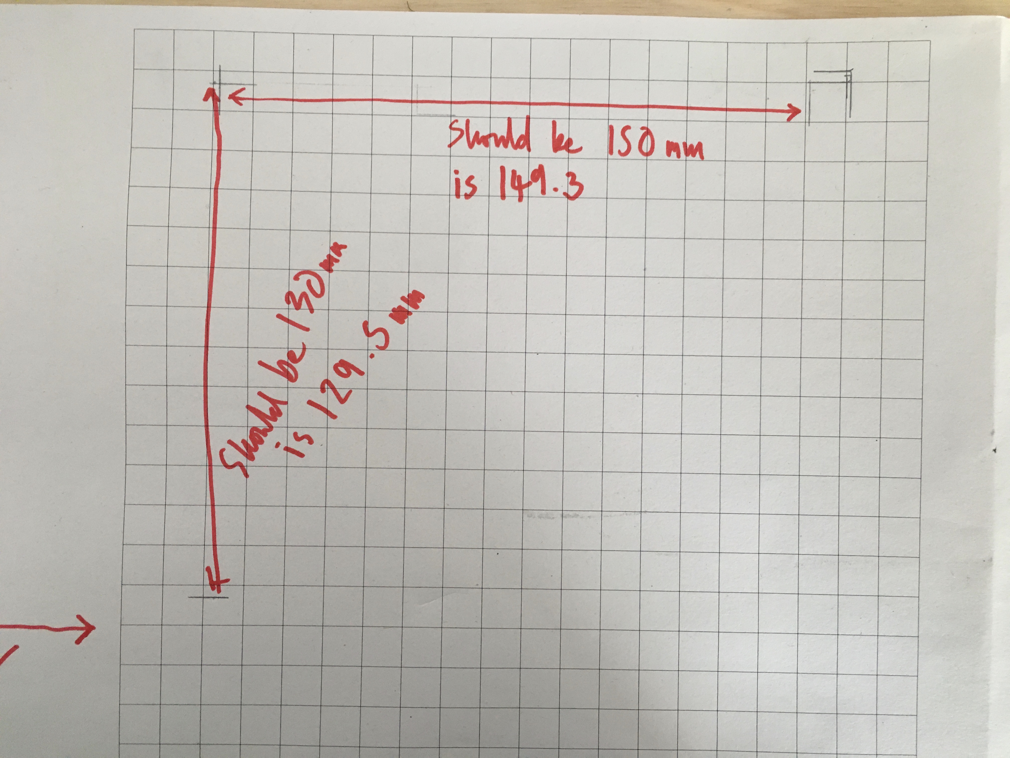
I strapped a pencil lead to my hot end and used it to draw some lines that I then measured with my callipers. I’m seeing an error of 0.5mm over 130mm in Y and 0.7mm over 150mm in X.
I probably should do more tests to check the repeatability of my measurements… But assuming these are right, that wouldn’t account for the print being 0.6mm out over 25mm as… (150/25)*0.6 = ~3.6mm error over 150 mm which is an order of magnitude bigger and would have showed up just by eyeballing the hot end against the grid I printed on my laser printer.
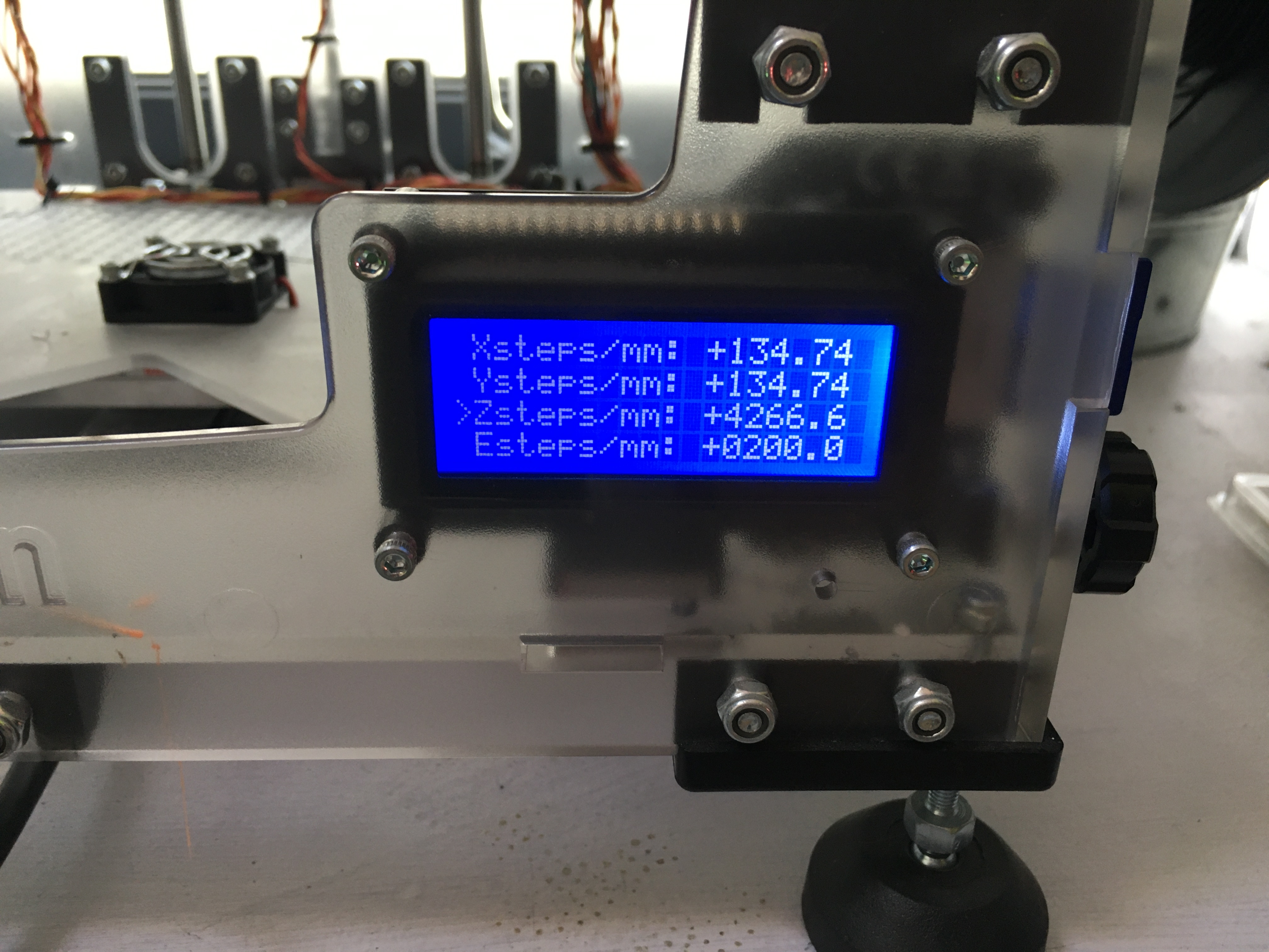
Anyway here’s what the steps / mm is set too:
Just in case I was going mad, I have also checked the GCode emitted by the slicer and it definitely sets it to metric, so the printer takes the gcode instruction to move X mm and decides how many steps that equates to which means its valid to use the thumbwheel on the printer to adjust the XY position to draw the lines.
I agree that the Horizontal offset thing feels like a kludge. I don’t have a vRef setting anywhere, but if I tweak the the flow rate in the slicer for the outer/inner wall rather than trying to use horizontal offset would that have the same affect as adjusting the vRef? What I don’t really understand with either of those settings is why they would have the effect that the gcode generated from the test cube STL is always accurate but the gcode from the leg lock STL is not? It’s not the actual leg lock STL itself as I’ve checked this, it’s something in between.
All this stuff is a bit of a quagmire, but at least I’m doing a great sales job for Ryan’s ready printed kit! @vicious1
Vref adjusts the strength of the motors by setting the motor current. The drivers have a little screw on them (drv8825s do, at least).
Motion error is often a percentage and an absolute. So the error might be 0.5/150 or it is always 0.5 (or it is 0.15/150+0.35). Backlash, for example is an absolute error. It might be 0.5mm to pick up the slack before moving at all, and then move 0.5mm less than you asked. No matter how far you sent it.
Our own Jamie has a test pattern generator for use in cnc. But I don’t see any reason why you can’t use it for a printer if you put a pen on it. It will give you very accurate results, so you need the pen mount to be rigid.
I suggest trying your pencil test again at a couple of different lengths. Then you’ll get a feel for whether the observed variance is proportional to travel, or always the same amount. Always the same amount would point me towards a mechanical issue like a loose pulley grub screw. Proportional to travel would indicate steps per mm might be off, or something like the teeth of the pulley doesn’t match the pitch of the belt.
Assuming the printer parts are all a good mechanical match, and since you say you’re new to getting accurate prints from this printer, I also suggest working through the Teaching Tech 3D Printer Calibration process. This brings together suggestions from various places into a single-threaded procedure that works through each “layer” (mechanical, temperature control, bed adhesion, etc.) of the 3D printer system. The sequence he has chosen ensures that each layer gets set as a firm foundation upon which to build the next refinement in print results.
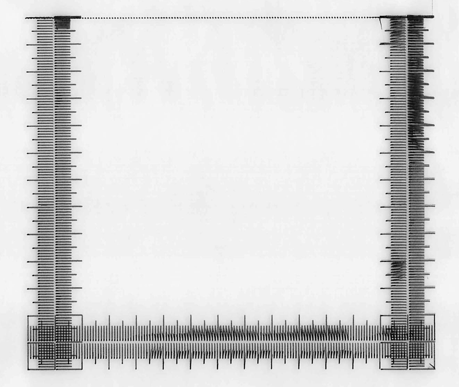
So I tried the test pattern generator. Seems like a backlash issue, but I can’t find where it is. Also, something weird is going on with the interpretation of the gCode for the pattern as well. The first 2cm are missing from the top and when this was drawn the printer went over these lines multiple times so it was executing instructions for moving in x and z but not in y until it had got through 2cm worth of y instructions, then it was happy. I tried a smaller 100x100 pattern but had the same problem with the first 2cm missing from one axis. I’ve looked at the gCode and I can’t see why this would happen. the print area is 190*200 so its not that either. So I don’t trust either the mechanical setup or the firmware. I think I will give up for now and either save up for a set of parts printed by Ryan or a Prusa printer.
Gcode is just saved to SD card and printed using the print from sd card feature in the Marlin firmware that runs on the printer. There are no negative numbers in the Gcode. I’m going to try printing a 2mm thick flat test pattern in PLA the same size to see what I get.


 What speeds are you printing at? My nicest looking and most accurate print so far has been printed at 60mm/s with walls printed first. Is that fast?