Well, it’s been some time since I’ve had to post here. But I’ve come into a problem, even with 2 days of trouble shooting, I cant figure out.
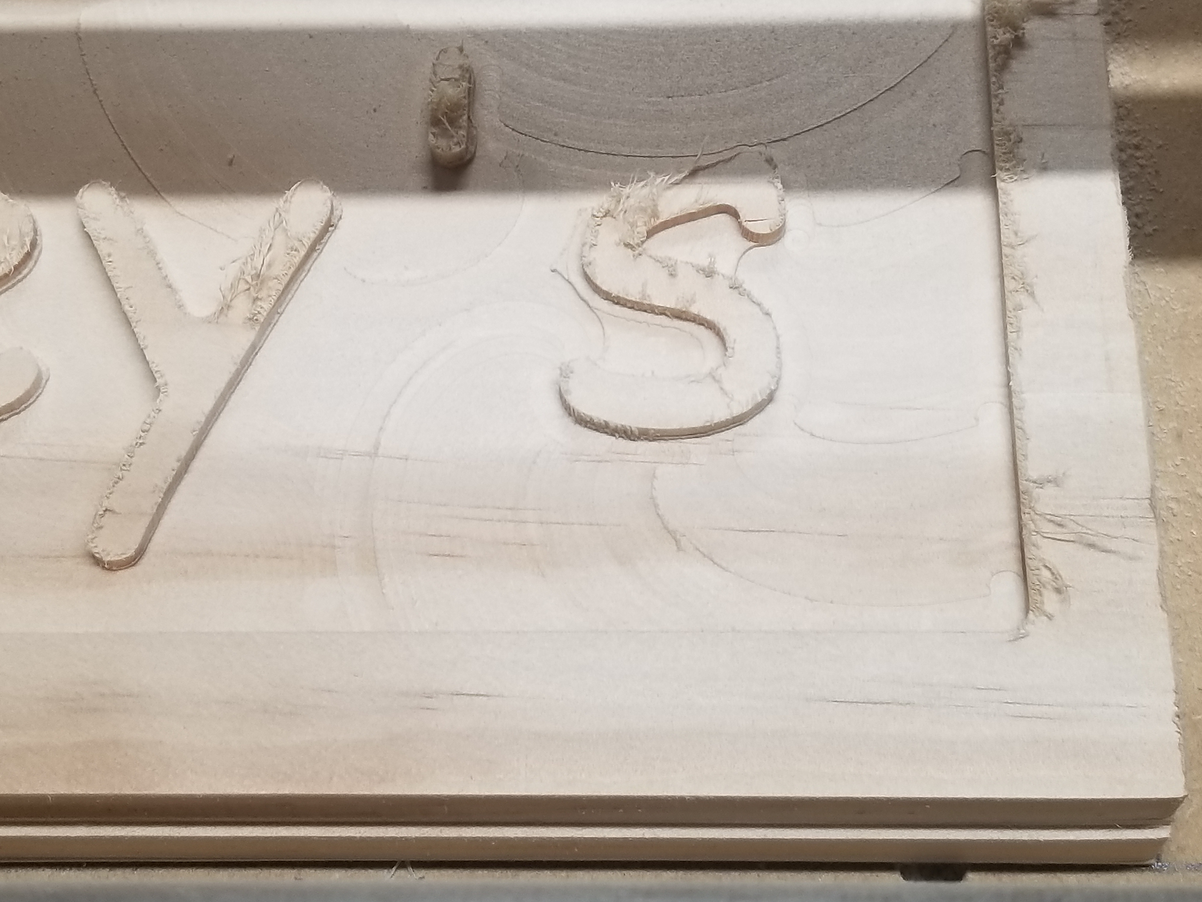
My problem can been seen in the photo below, but just incase your unable to see it, I was creating a sign and I’m leaving behind peaks and valleys, and also the lines where the tool has ran its path.
Here are my trouble shooting steps thus far
Software: (fusion 360)
Feed rate : 100mm -1350mm
Plunge rate : 15 to 45% of feed rate. Normally, I use 35%.
Step over 10 to 40%
Ramp, plunge, and helix. All with the same result.
Mechanical: LR2
Resurfaced spoil board
Checked all bolts for tightness
Cleaned belts, motors, end stops, and tubes.
Rewired router to above the table to allow no extra pressure on the 611 router.
Removed and cleaned wheels, reinstalled
Replaced the 1/8" flat bit with a new one.
Was thinking that maybe the machine needs to be trammed, but not certain how or if that’s even possible with the low rider. Maybe it is and I just simply cant wrap my mind around it. (I’m guessing this is the case )
Would anyone have any suggestions, or extra trouble shooting ideas I can try ?
Reducing the stepover can help. You also need to check that your tool is perpendicular to the surface (ryan has a perpendicularity tester on thingiverse).
The other thing that might be happening, especially if you are removing a lot of material, is that the wood (which is probably kiln dried) is dried with a lot of internal stress. When you remove half of it, it will bend, making the surface higher or lower. I saw this on a cabinet door I carved. The best battle against that is to do the rough pass pretty rough (lower stepover, leaving 1mm or less) and then do a finishing pass to clean it up.
Thanks for the reply, Jeff. This is happening on a finish path. I cant see the step over being the issue with my test of 15 to 45%. Every test resulted in the same issue. I will give the perpendicular test a try.
Clean wheel path? No chips or debris in the way of the wheels? How are your Z-axis couplers? Still neat and tidy, or stretched out and curly-fry’d? Leadscrew nuts still in place and kept from rotating? Gantry still reasonably stable? No floppiness at the router plate? How’s your collet grip?
The numbers are rather simple. The number I provided, were different settings used to determine a bottom issue. However. None of them made a difference in trying to solve the main problem.
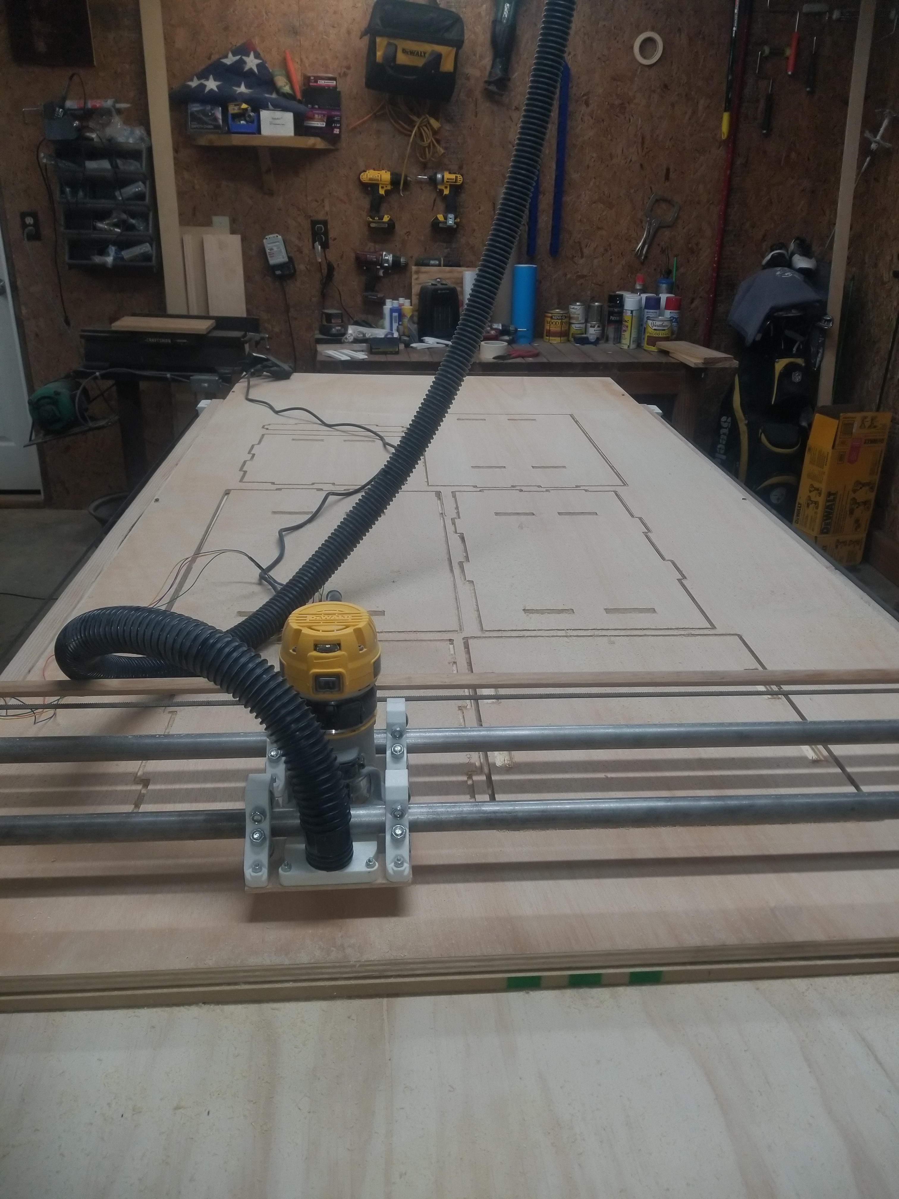
Hmm here’s my lowrider. This was on a previous job I finished.
100mm/s is too fast so I assume mm/min, 1350mm/min is 22mm/s still too fast, units matter here as does complete info. I have seen people try to use very crazy speeds. Screenshots of stepover, plunge rates, rapids (biggest issue ever), gcode format.
Might as well attach your gcode and I can look at it.
You attached a picture of the router and a piece of wood I can’t see either side of the actual machine
I would like to help so information overload is so much better than the bare minimum here. So put it all up or the first dozen or so replies will be all questions from us and no solutions.
Thanks for the reply, Ryan. It might be a day or two before I can reply fully to your message. My daughter had surgery this morning, so I’ll be out of the shop for a few days.
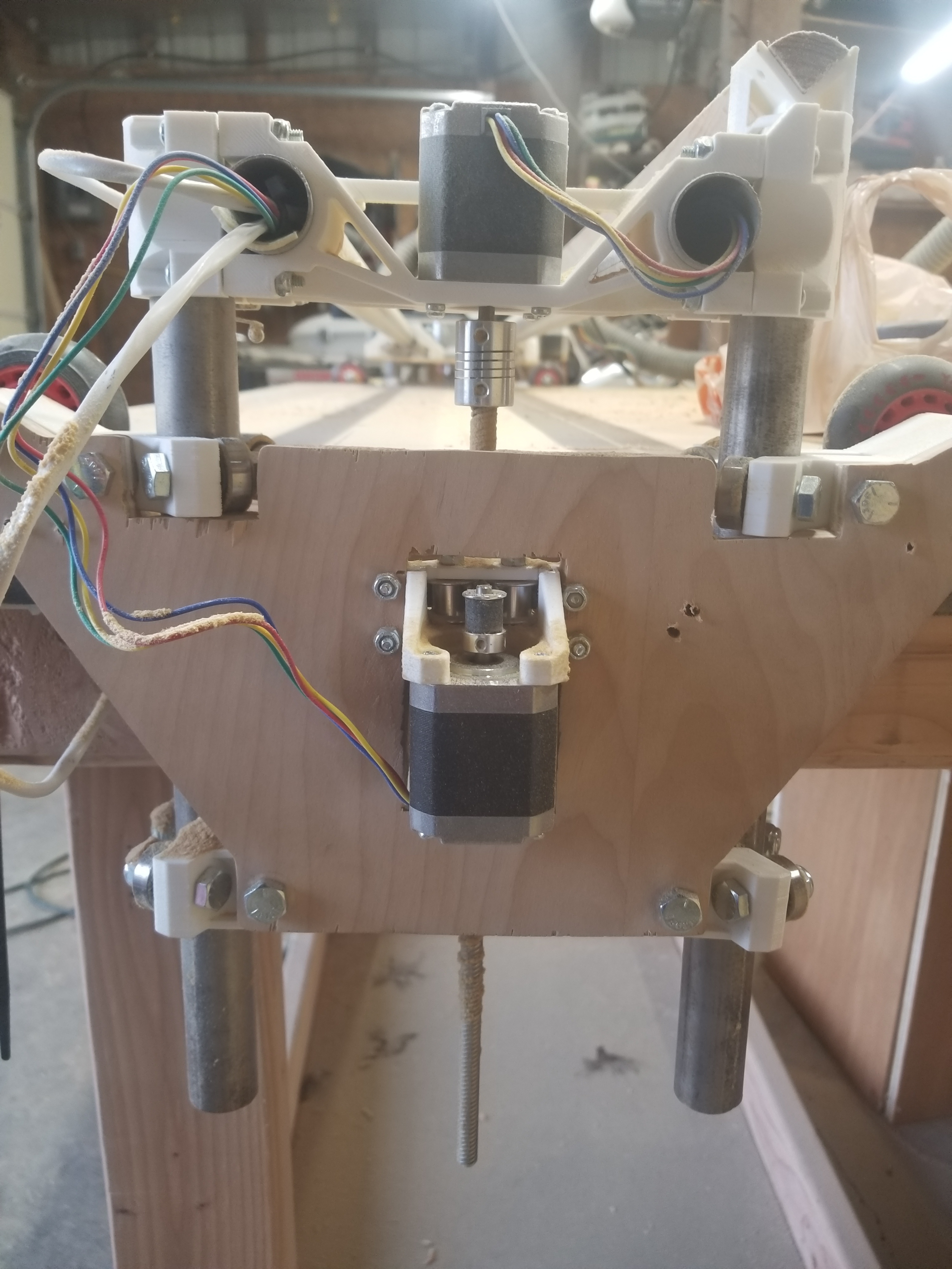
Sorry for not the so in depth issue but I was able to get 5 mins to run out to the shop and take some pictures. Here is a level on my gantry. Which now I believe maybe the y playes are off just a tad.
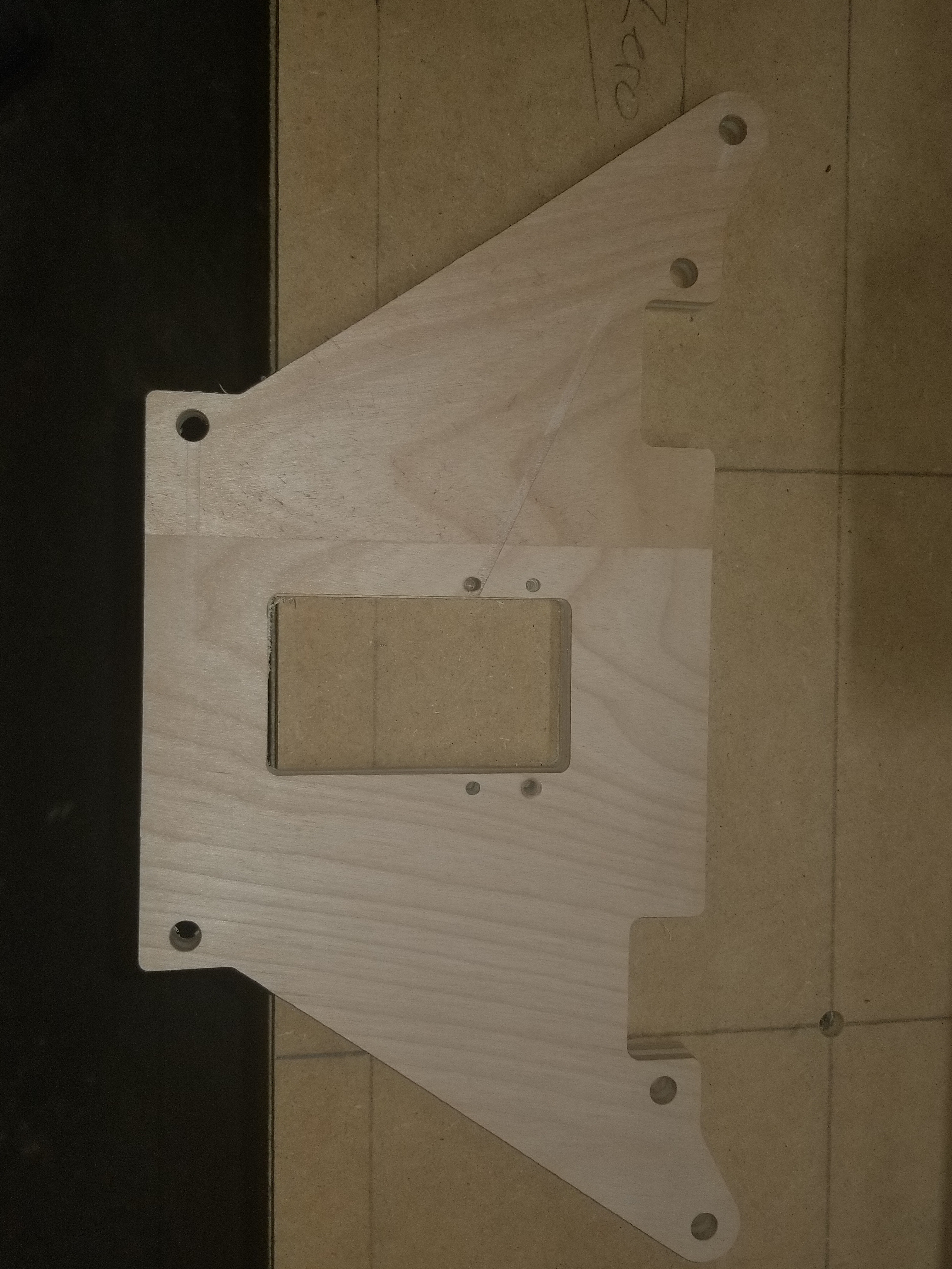
The second photo is the y right plate, the third is the y left side. Please dont mind the wires, I’ve been troubling shooting.
My machine runs on 2x4 that were jointed on 3 sides. I should have done the 4th, but ehh. Was tired and saw no sense in it. The table is made out of a honey comb figure. Should have taken pictures. Ontop of the honeycomb lays a sheet of 1" plywood. A 3/4" of MDF lays ontop of that.
I am running marlin, with dual endstops. 2209 drivers. And havent had an issue with those at all thanks the @jeffeb3.
The machine is actually pretty rigid. I have 1" OD SS throughout. The belts are just under to tight which gives me very smooth operation. All printed parts where completed on a strat 250mc printer (industrial ) so in certain those are correct.
I will have to give photos of my fusion system later this evening after the kids get into bed. Hopefully that was better than my first post
While cutting out new Y plates. I found one issue. Well two, maybe 3. First and for most. Slower speeds have resulted in better results. 350mm/min seems to be ok. Second, my leadscrew on my right Y plate, must have came lose. Got to watch it this evening actually move up and down causing my gantry to be WAY off. Third, my gantry is still unlevel, however I do believe I probably was in a hurry the first time around. Time will tell but I’m almost positive I got excited and went to fast. I’ll keep posting as I find out more.
 )
)