I’ve been wanting to build a sand table for a while and finally got around to it using parts I’ve had laying around. I currently have it running klipper in cartesian mode on a mks gen 1.4 board which is essentially an arduino and ramps1.4 in one board. I’m having trouble running the code on it and was wondering if there was any way to run it using a different program.

2 Likes
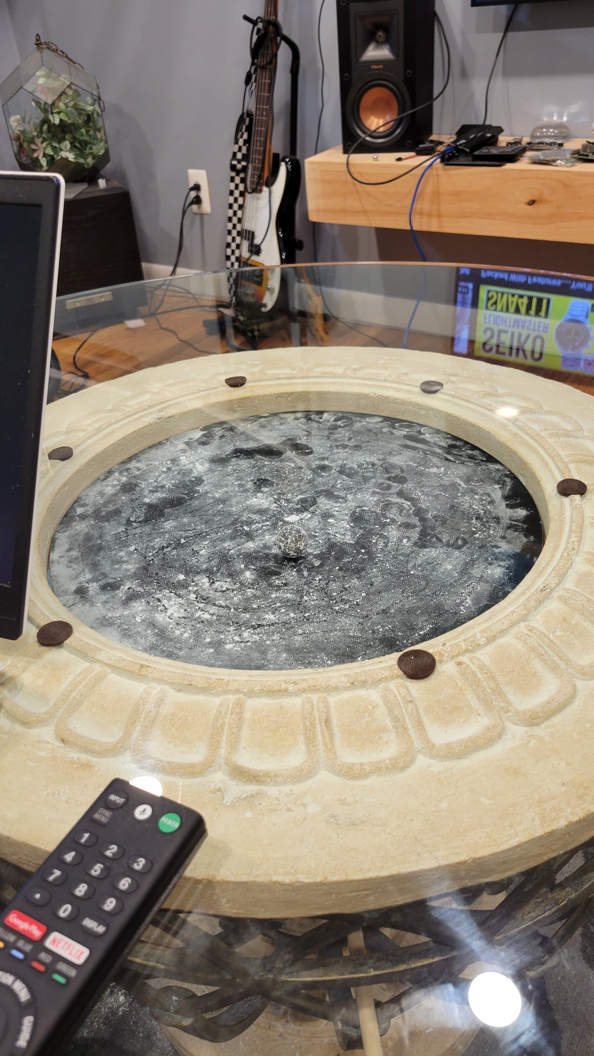
It looks like you have built a machine with one axis for theta and one for rho (or radius).
I can’t put my finger on the post, but I thought I just helped someone with this a month ago or so.
The closest format is .thr format from sandify. But it is obviously wrong because it isn’t gcode. I wrote a python script to read in thr and output gcode. I wrote it and shared it in repl.it. similar to the one I wrote for the scara machines.
This is the script: Thr2PolarGCode - Replit
I have also seen some people trying to replicate the sisyphus system with Arduino code to control the table and use thr files for input. I can’t vouch for how easy it hard that is to do.
1 Like
Thanks for the quick reply. Unfortunately I know very little when it comes to coding. I’ve been able to build 3d printers but I suppose that was easy compared to this, as there is not much that hasn’t been figured out already. Perhaps I have bitten off more than I can chew at the moment, I don’t believe I’ll be able to forge my own path with this setup knowing very little about code. I think I’ll have to take some time to try to learn some coding or maybe get a more ideal setup for this project.
It is at least moving, just not as expected, I probably just need to play around with it more to figure out the proper settings.
You don’t have to do it alone. We can help you. The build looks awesome. This stuff can be intimidating, but it is made by humans and it is meant to be understood by humans.
The script I posted can be used in the browser and you probably don’t have to change it. You can upload a different thr files there and run it. The transformed.gcode will then have your gcode you need.
But we should start with your machine. Start with one issue. Can you move the machine? Yet answering these question: what did you do? What did you expect? What did you get instead?
2 Likes
Thanks for the kind words. I was trying to calibrate the steps and I’m not sure if I’m doing it the right way. I made it so theta rotates close to one full rotation with 52 steps, and rho is calibrated to move the right distance that is called from it.
Everything moves the way I tell it to but when I load a spiral pattern gcode generated from sandify it does a weird figure 8 pattern instead. I assume I have something configured wrong where its telling the machine what I want it to do but the machine is doing its own thing.
I may try to make a breakout board and run sandtrails from a raspberry pi since I have all the parts needed for that, but I’m not sure if sandtrails would work with the way mine is built. I’ll try to make this in the meantime, since the belt I made for theta broke and I cant do anything more until the replacement loops I ordered come.
Let’s be really careful with the terms. I’m not sure what you mean by steps here.
The script assumes that 6units are one rotation. So from zero, G1 X6 would rotate one entire rotation. The radius axis is 1unit from the middle to the extreme. So from zero G1 Y1 would move from the center to the outside edge.
You would either need to edit that script, or adjust your “steps per unit” in your firmware to make that true. M92 is the command in marlin to change steps per unit. Klipper is a little different because it computes that itself.
I didn’t know that. That’s probably why it’s acting weird then. This is the configuration I have setup. I guess I meant to say rotation distance. I don’t see how I would translate that to being interpreted as 6 or having y being 1 for a center to edge movement.
[stepper_x]
step_pin: ar54
dir_pin: ar55
enable_pin: !ar38
endstop_pin:ar3
microsteps: 32
rotation_distance:50
position_endstop: 0
position_min: 0
position_max: 1000
homing_speed: 10
#gear_ratio: 4:1

[stepper_y]
step_pin: ar60
dir_pin: !ar61
enable_pin: !ar56
rotation_distance: 73
endstop_pin: ar14
position_endstop: 0
position_min: 0
position_max: 300
homing_speed: 50
microsteps: 32


[printer]
kinematics: cartesian
max_velocity: 300
max_accel: 3000
max_z_velocity: 25
max_z_accel: 3
This may be the wrong way to go about this, I kind of just made it and put it together without doing any research on it first so I have no issue with starting over. If it is possible to make this work I will try but it seems like it may be easier to go with a different hardware setup.
Rotation distance is going to be significantly smaller than 6.
Do you know the ratio between the motor pulley and the big rotation gear? Is it fixed (with teeth)?
If it was 10:1, then rotation distance would be 0.6, I think.
The key would be: after you’ve made that change, a 6"mm" jog in X would rotate that axis one time.
I tried messing around with rotation distance and it wasn’t really making anything better. I found out that in klipper rotation distance is the distance in mm the axis moves for one full rotation of the motor. I have a 40 tooth pulley on the stepper motor and a 230 tooth pulley in the center that move the arm. So if 6mm should give me one rotation wouldn’t I have to change the pulleys to give me the proper ratio to make that happen.
It isn’t really mm in this case, it is those goofy units I made up (6/arm rotation).
So. If one rotation of the stepper motor shalt moves 40 teeth, and it is 230 teeth for 6 “units”, the math is like this:
40 teeth / 1 rev * 6 “units” / 230 teeth = 1.0434
So try that in your rotation distance and see if a jog of 6 ends up rotating one time.
Lets do that here also, jist to check the math.
If you jog 6 units, it will ask for 6/1.0434 rotations or 5.75 rotations of the stepper. 5.75 * 40 is 230 teeth. So that checks out.
If that doesn’t work, then let me know how far that went.