Primo Build 80x50cm workspace - Hamburg, Germany

Moin moin everybody,

long story short: due to coronavirus i suddenly got plenty of time :airplane: (mehhh) since spring this year. Thus I decided to do something useful. During university times some years ago I’ve enjoyed CAD modeling, constructing things and working with 3dprinters. Early this year I researched what was the best price/performance ratio and consequently I bought the Artillery Sidewinder X1 and dived into the printing territory.

Soon I found the MPCNC burly project so I wanted to start right away but then I’ve read that there would be an update soon. It was a little hard to wait but I think it was worth it, so I used the meantime to read a lot in this forum, certain Facebook groups etc. and last but not least following the main Primo thread as a silent reader waiting for the Primo release.

A few weeks after the 25mm F version was published I ordered in the end of July most of the parts and started the project of my first CNC machine, knowing that some parts may take a while to arrive from china.

During planning I wanted to be sure what total cost I had to expect with my specific setup so I used some conservative estimates to be on the good side :wink: …financially.
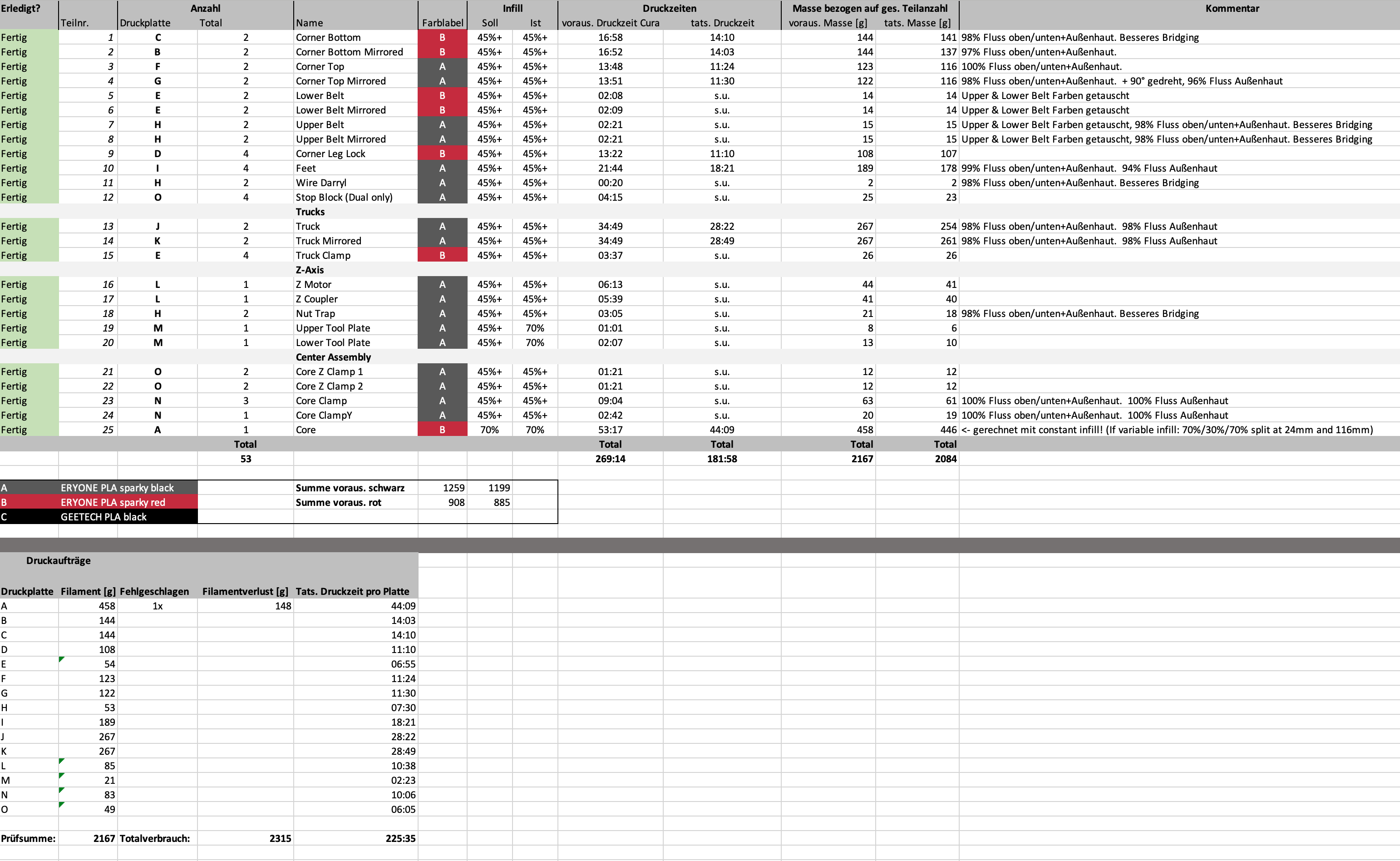
Since I am always trying to get the best price/performance parts with some exceptions, like shipping time, I created a project file in excel including a 3D printed parts sheet, a detailed list of materials and an actual data sheet of my Primo.

I recommend that to everyone having your things organized, errors will be minimized and you know your current project status.

Now the interesting part:

Facts:

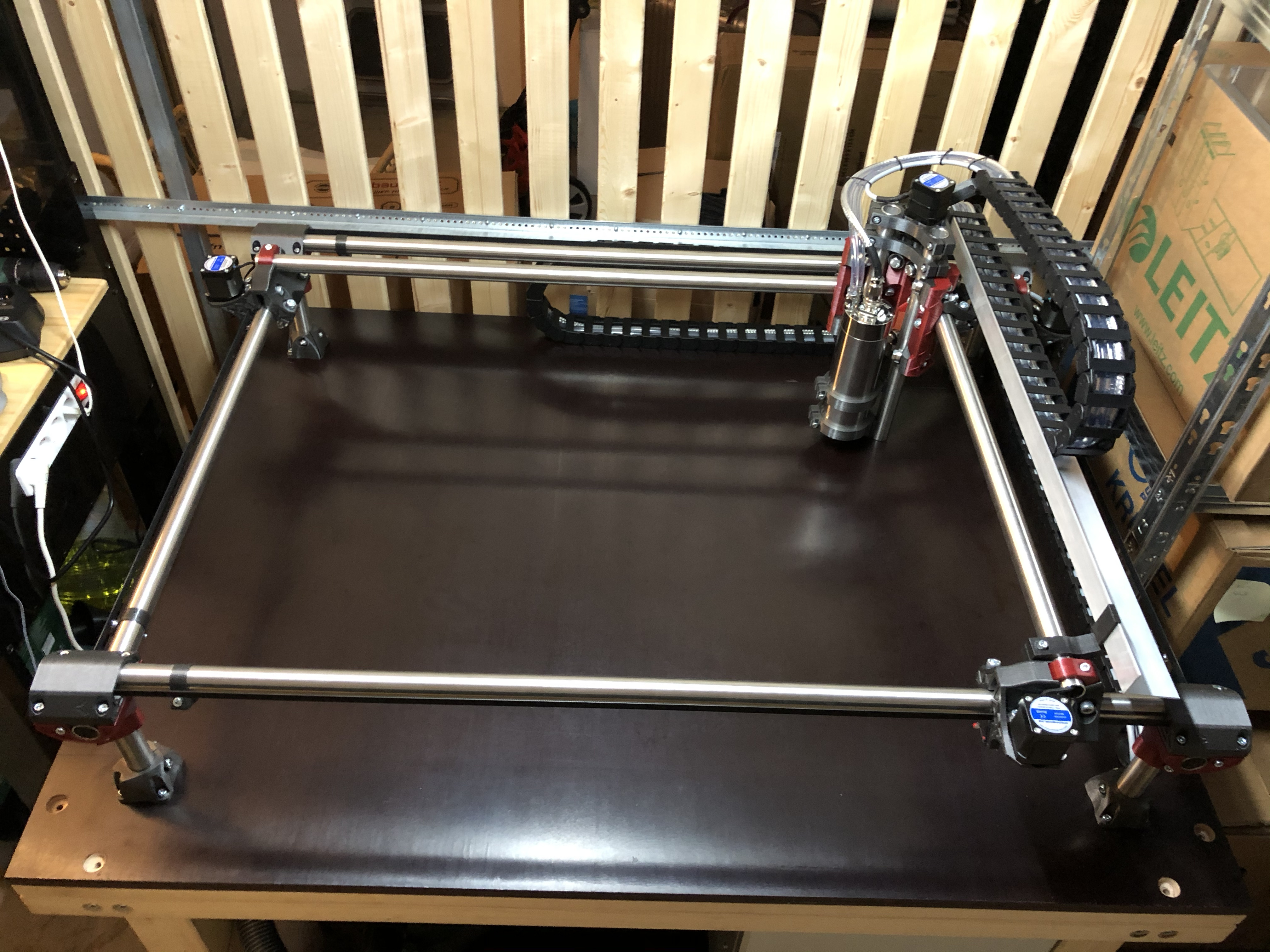
  • Workspace: 800x500x150mm
  • Table size: 1232x941mm
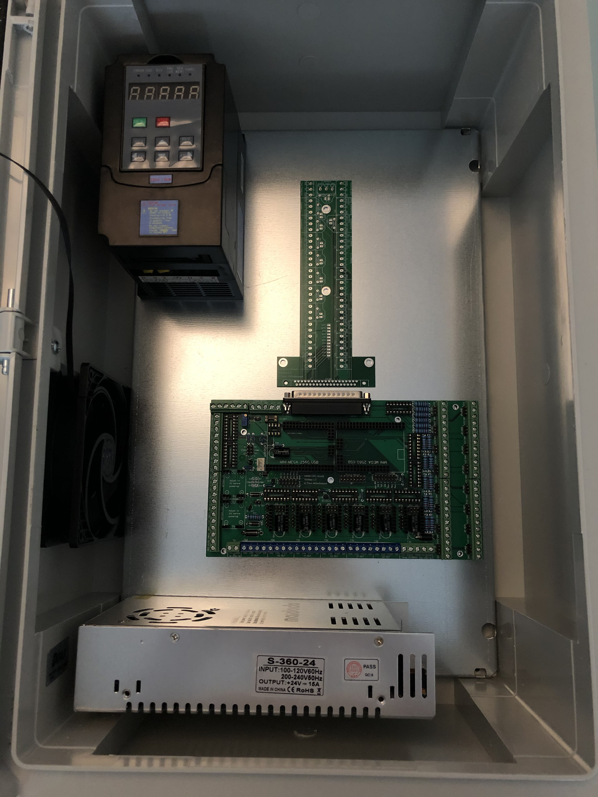
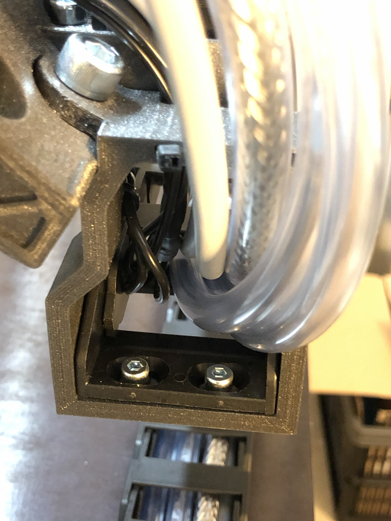
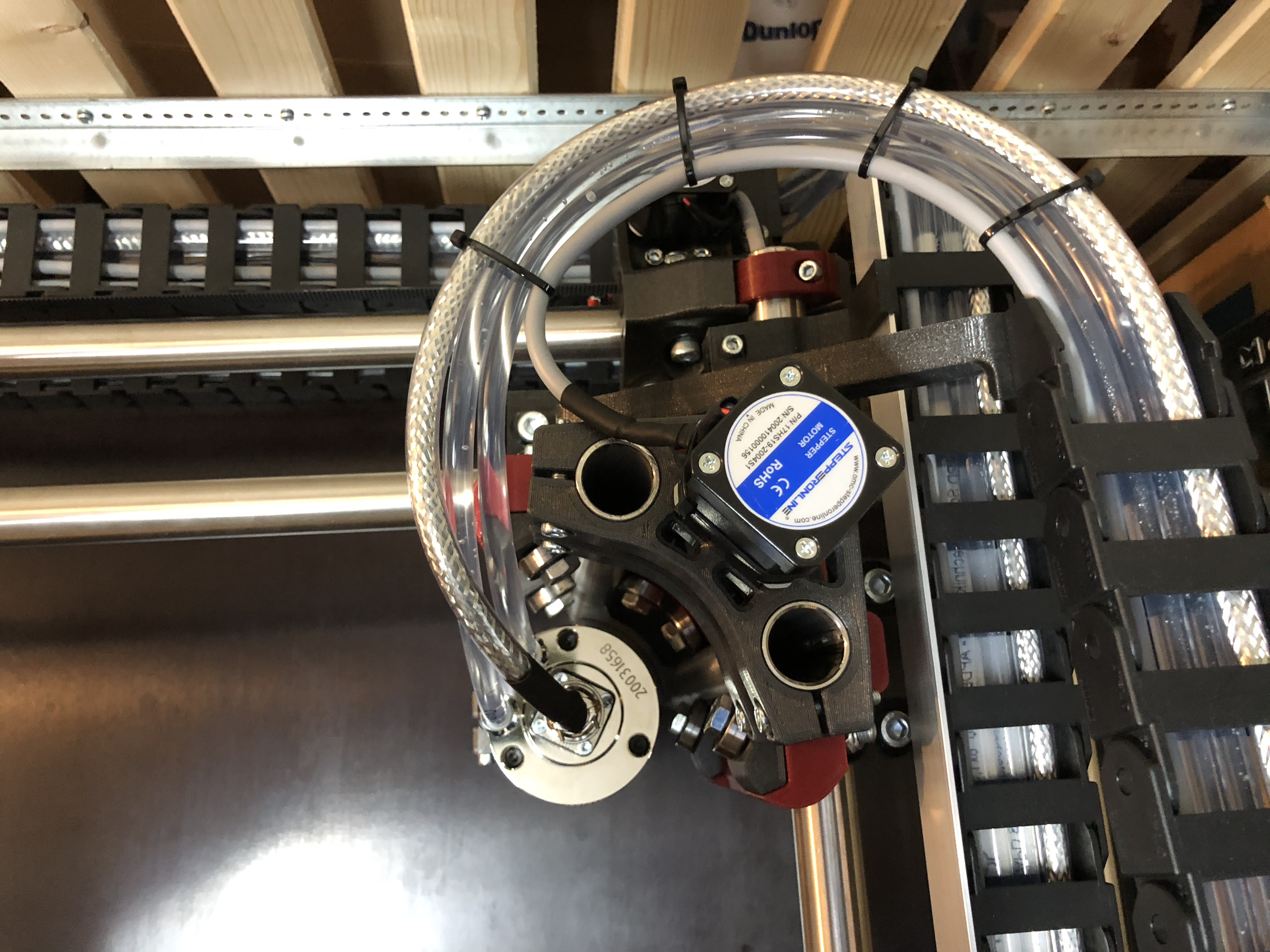
  • Water-cooled 800W ER11 spindle & 1,5kW VFD
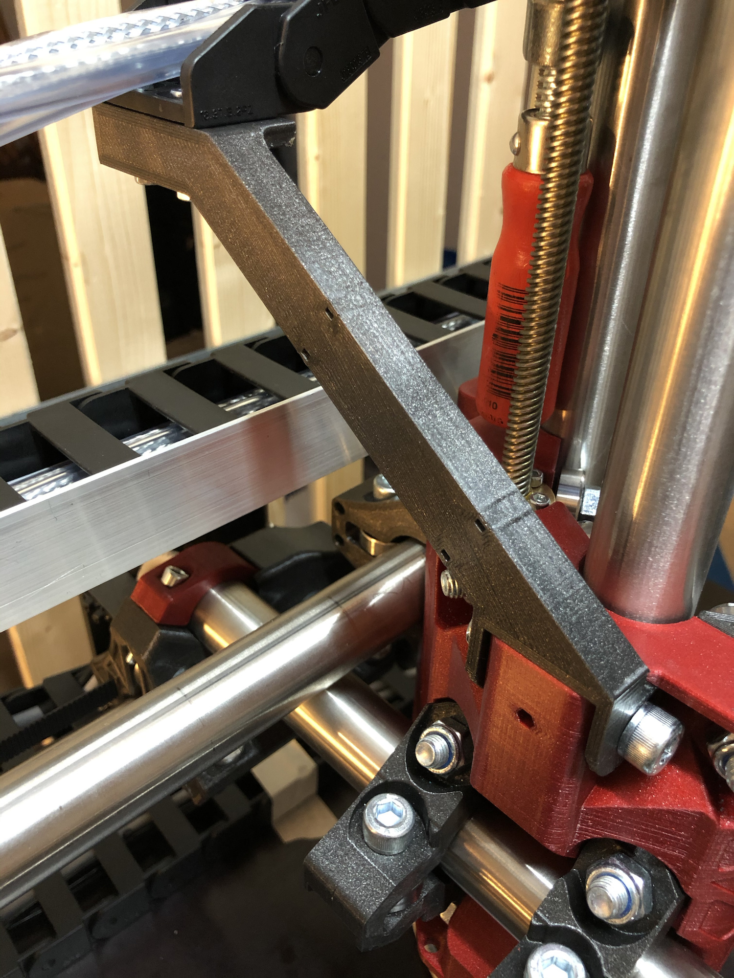
  • 25x2mm Stainless Steel tubes (V2A), 240k sanded
  • Filament: ERYONE Sparkle PLA Black & Red (Metallic effect)
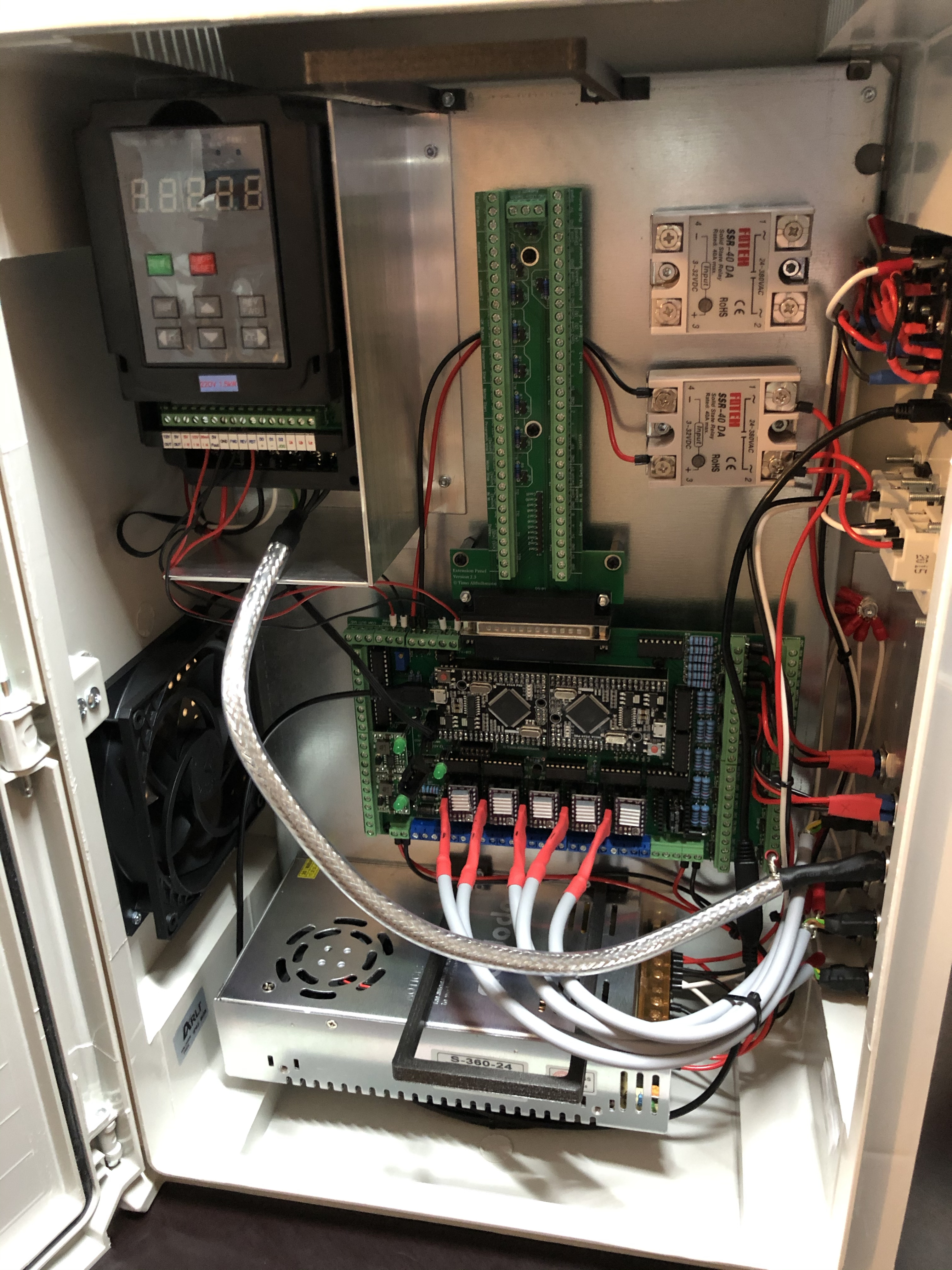
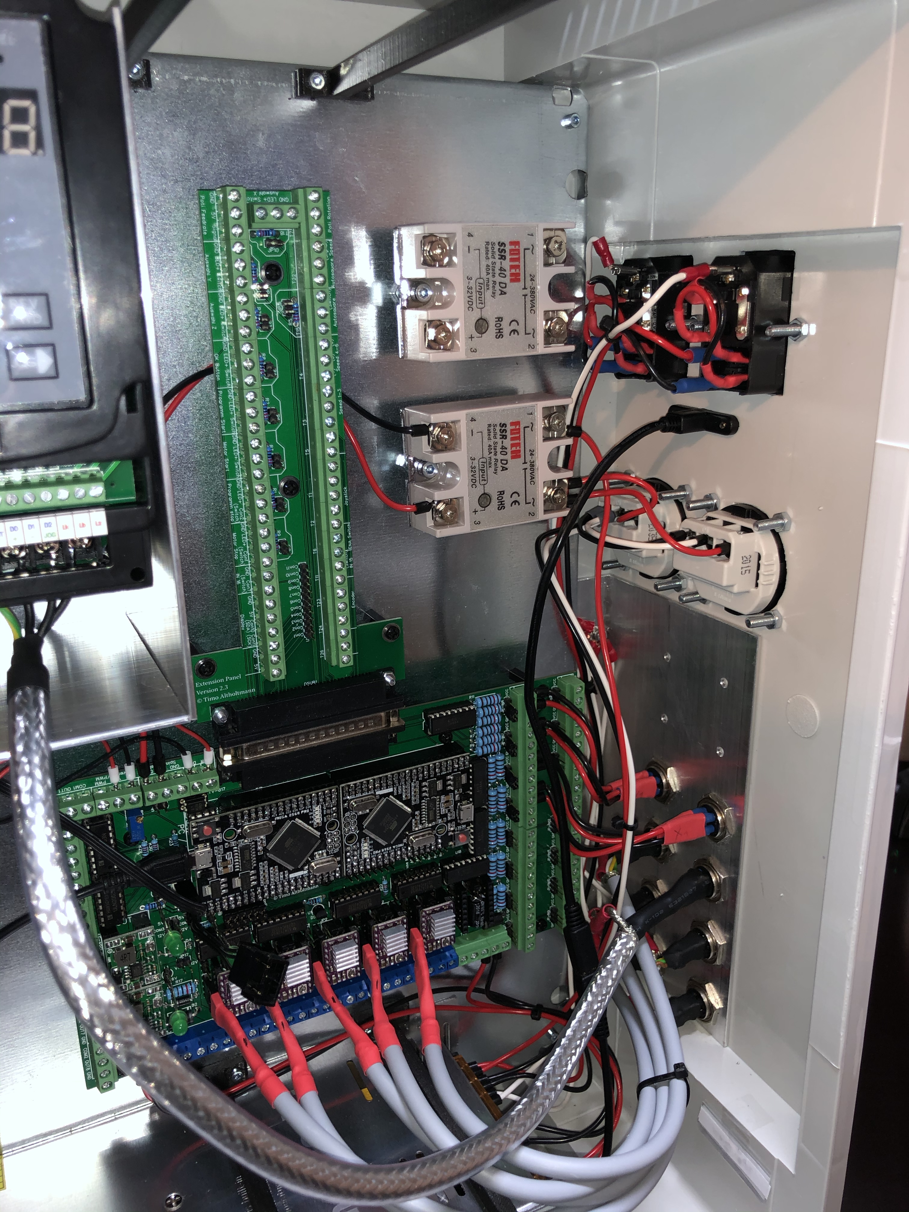
  • Board: OpenCNC Shield (relatively new)
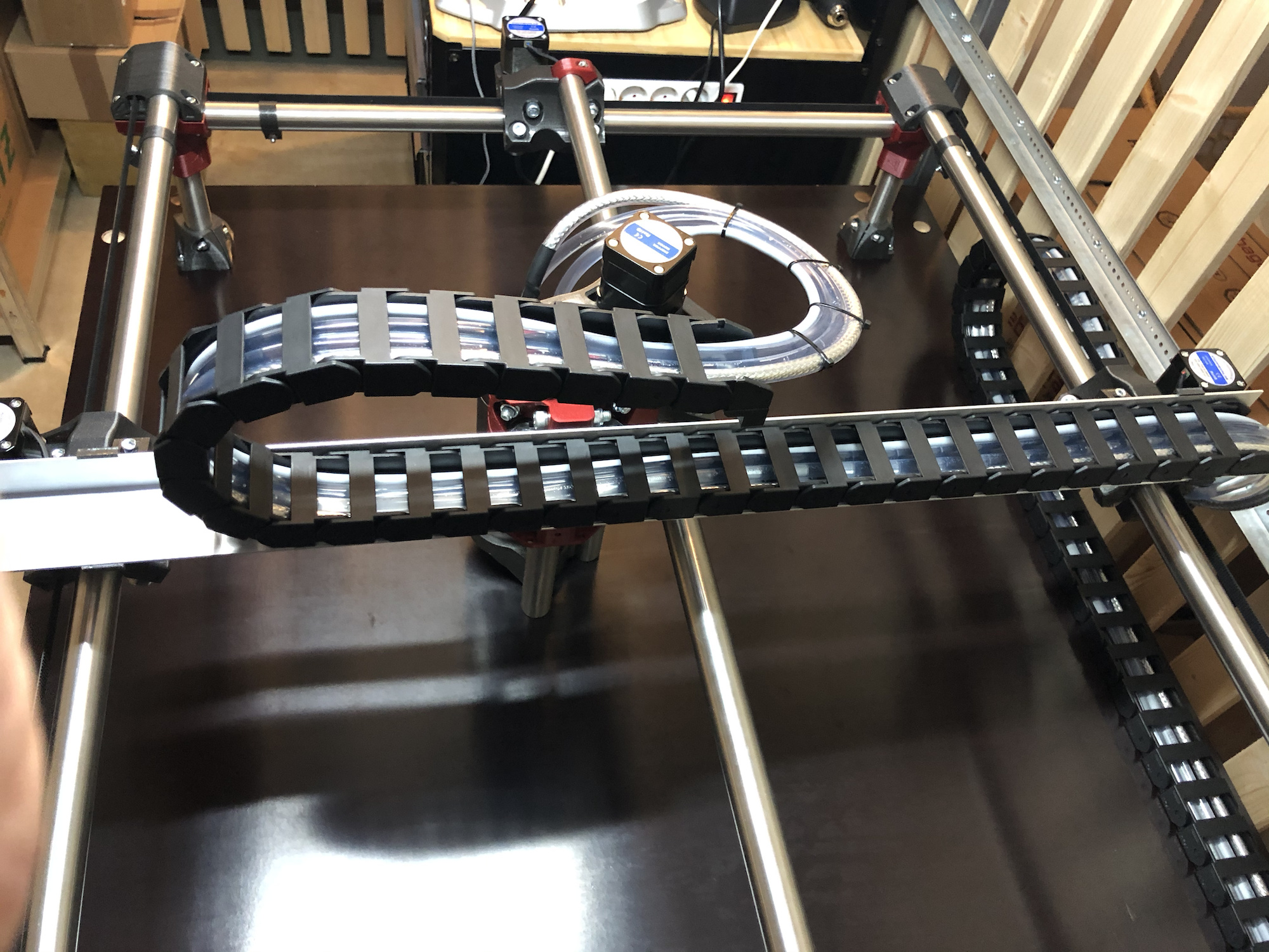
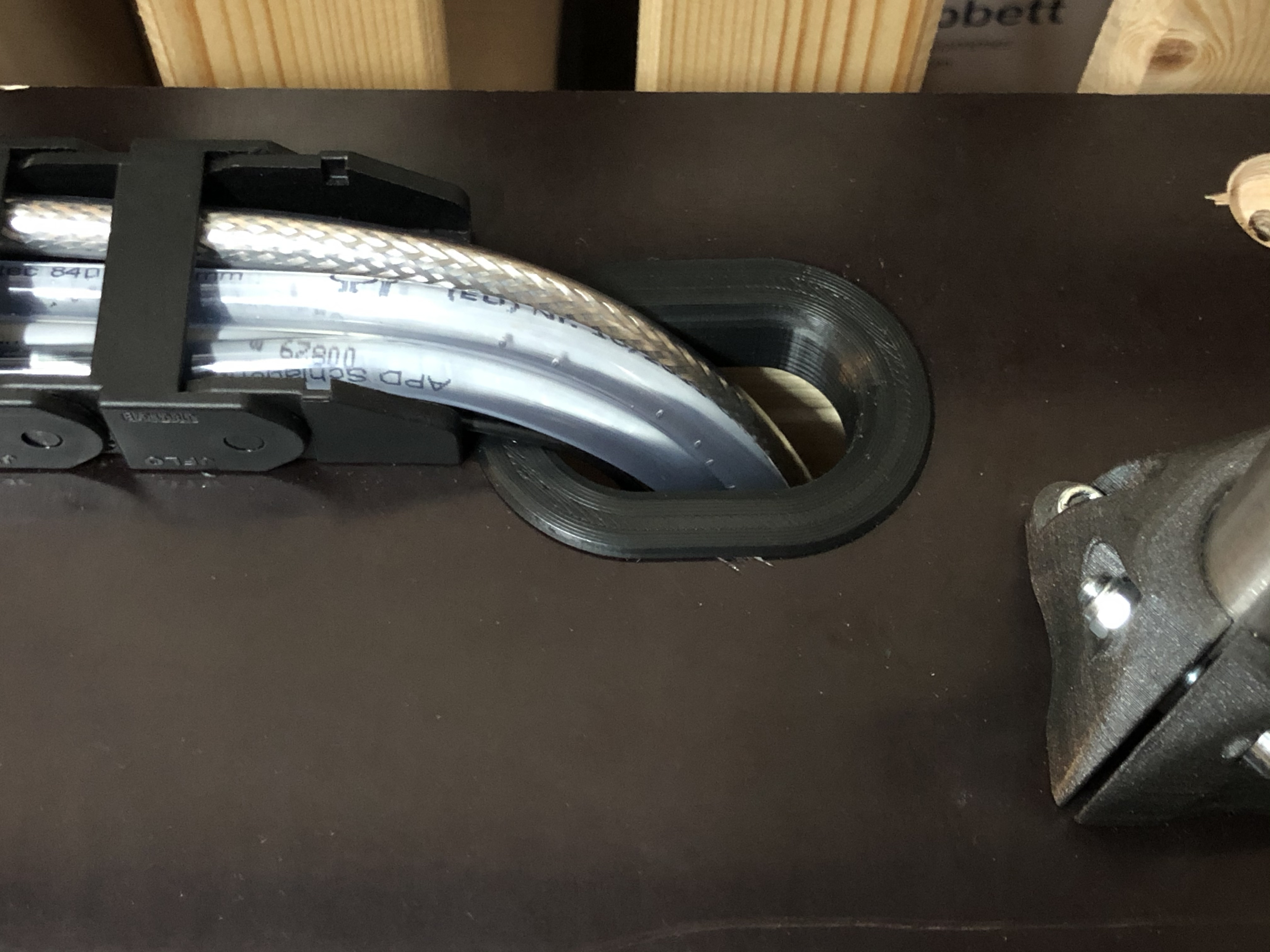
Some impressions:

Organisation:

First Prints: here I checked the dimensional accuracy if the bolts and nut would fit.

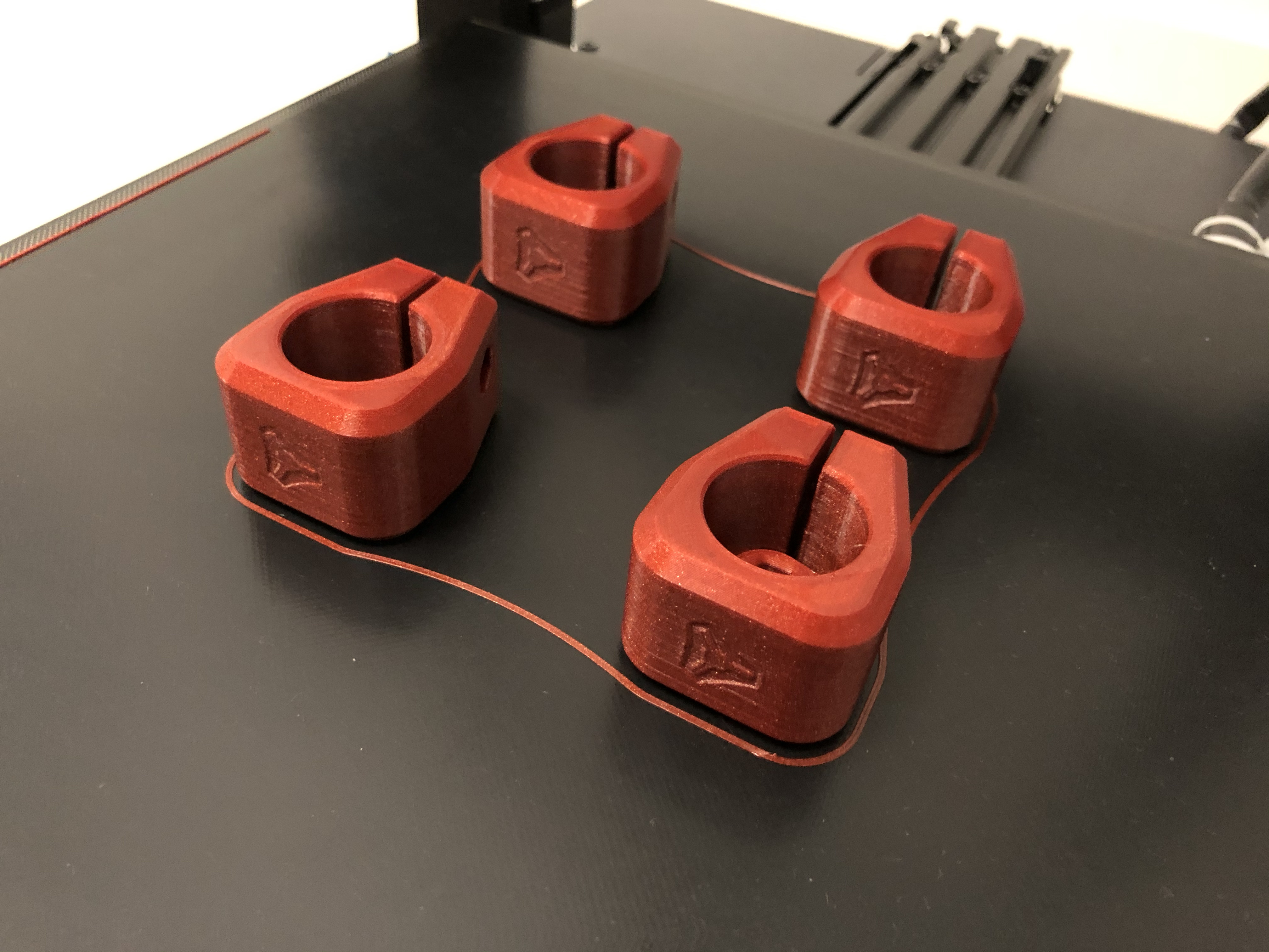
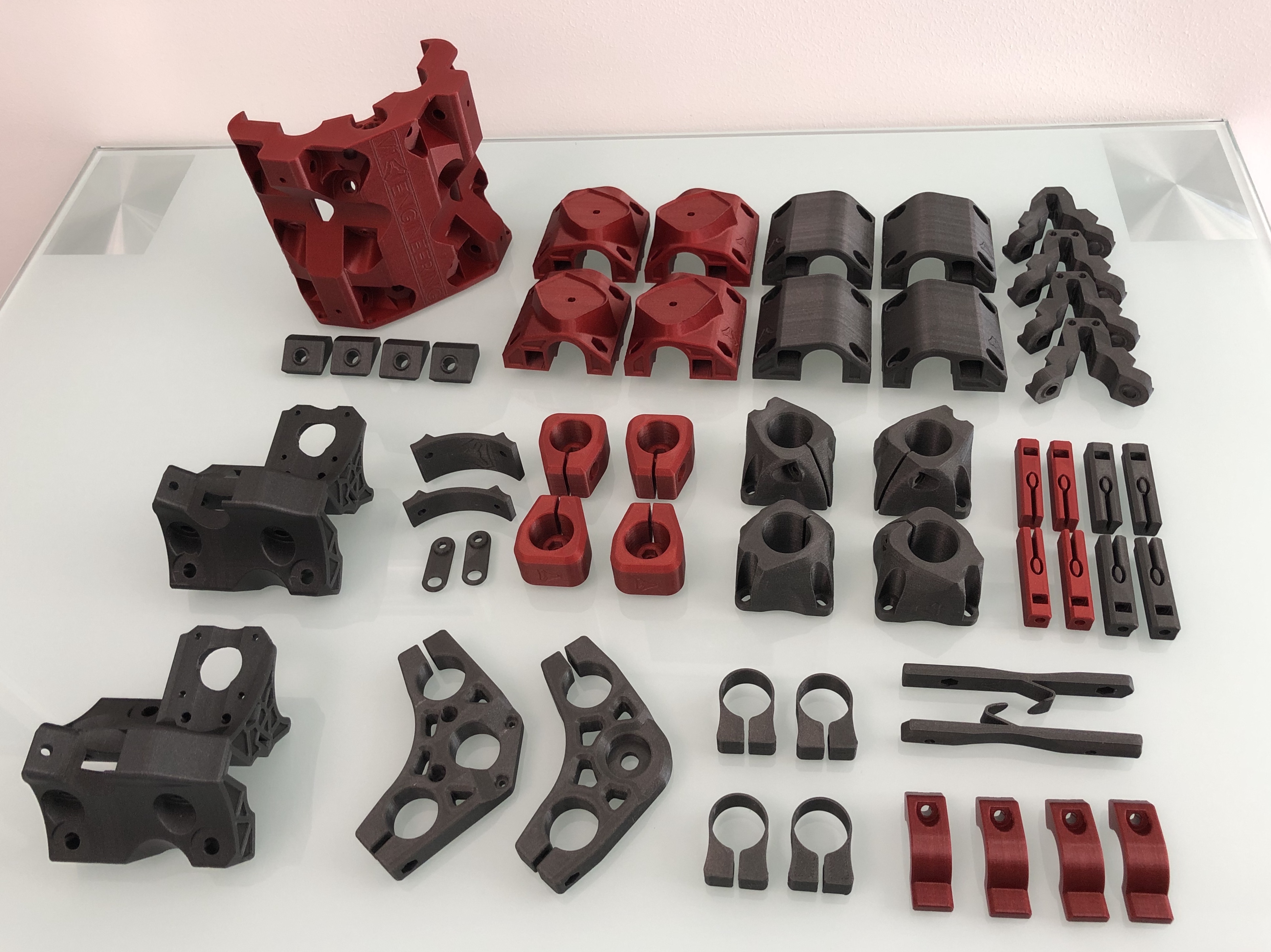
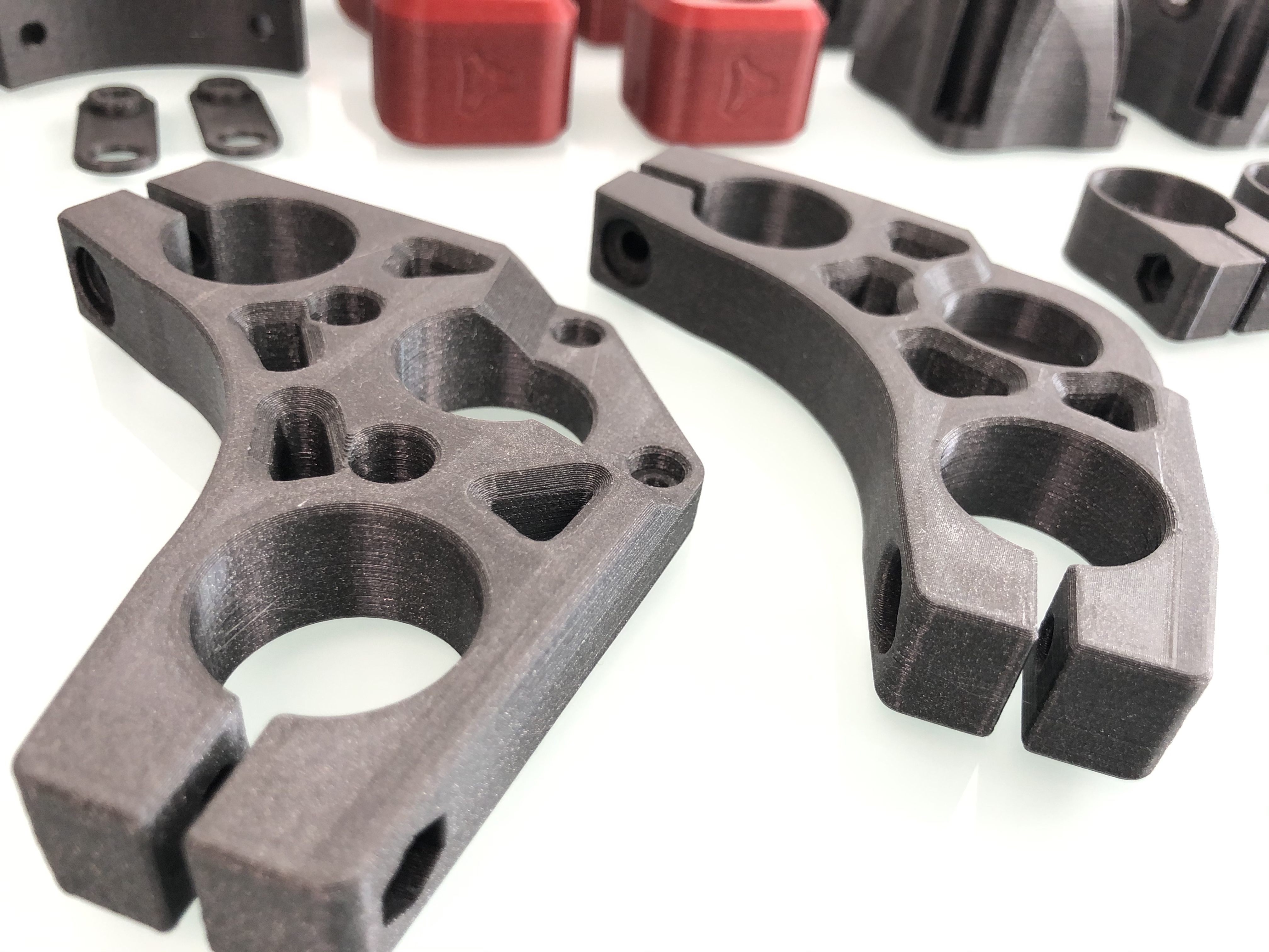
Some sparkling grey:

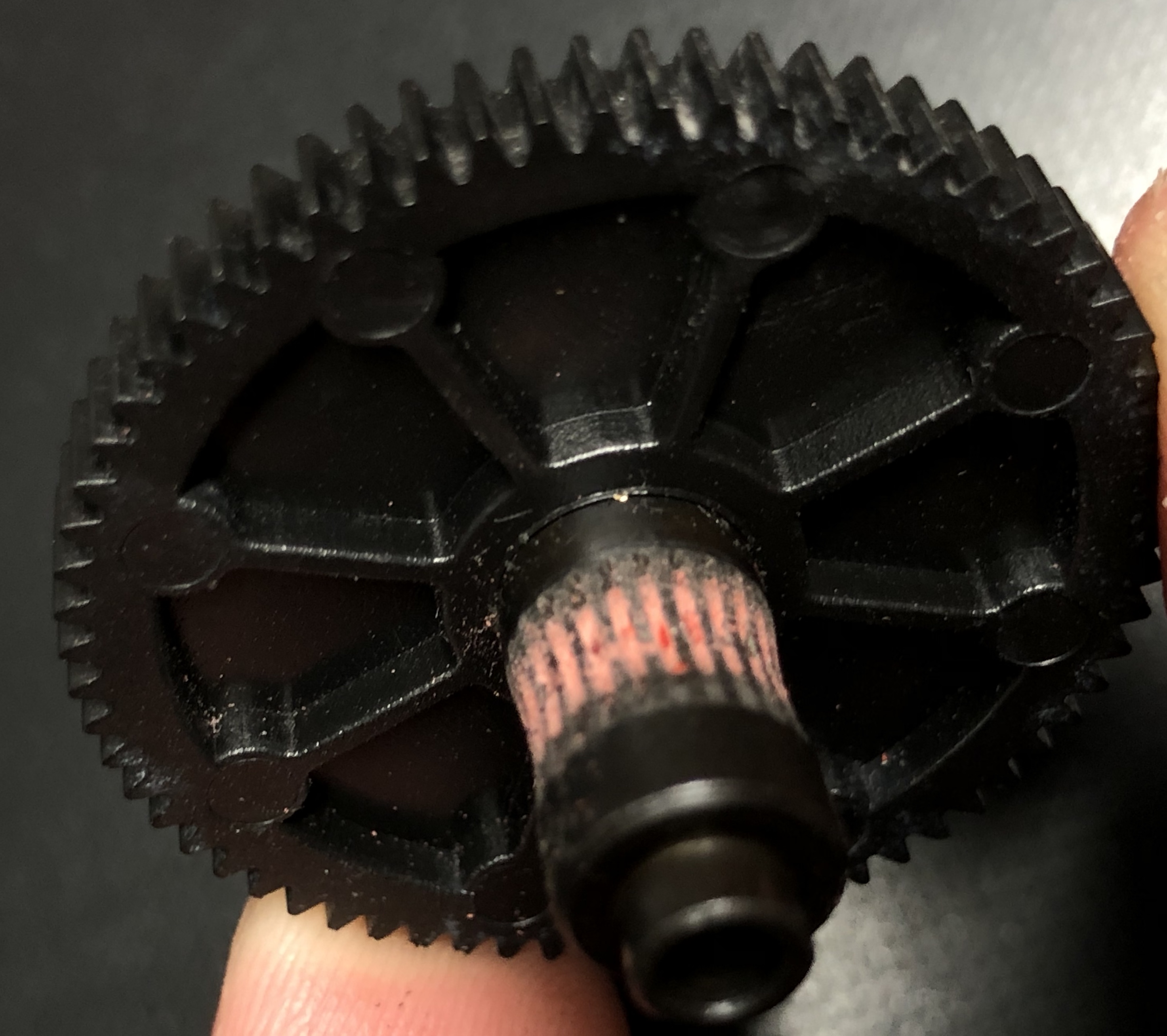
Core print fail due to clogged nozzle (first time having this issue, reason is unknown. I disassembled the extruder, changed nozzle and all further prints were good). You all said, it’s a learning experience and you were 100% right! :smiley:


Succesfull core print:

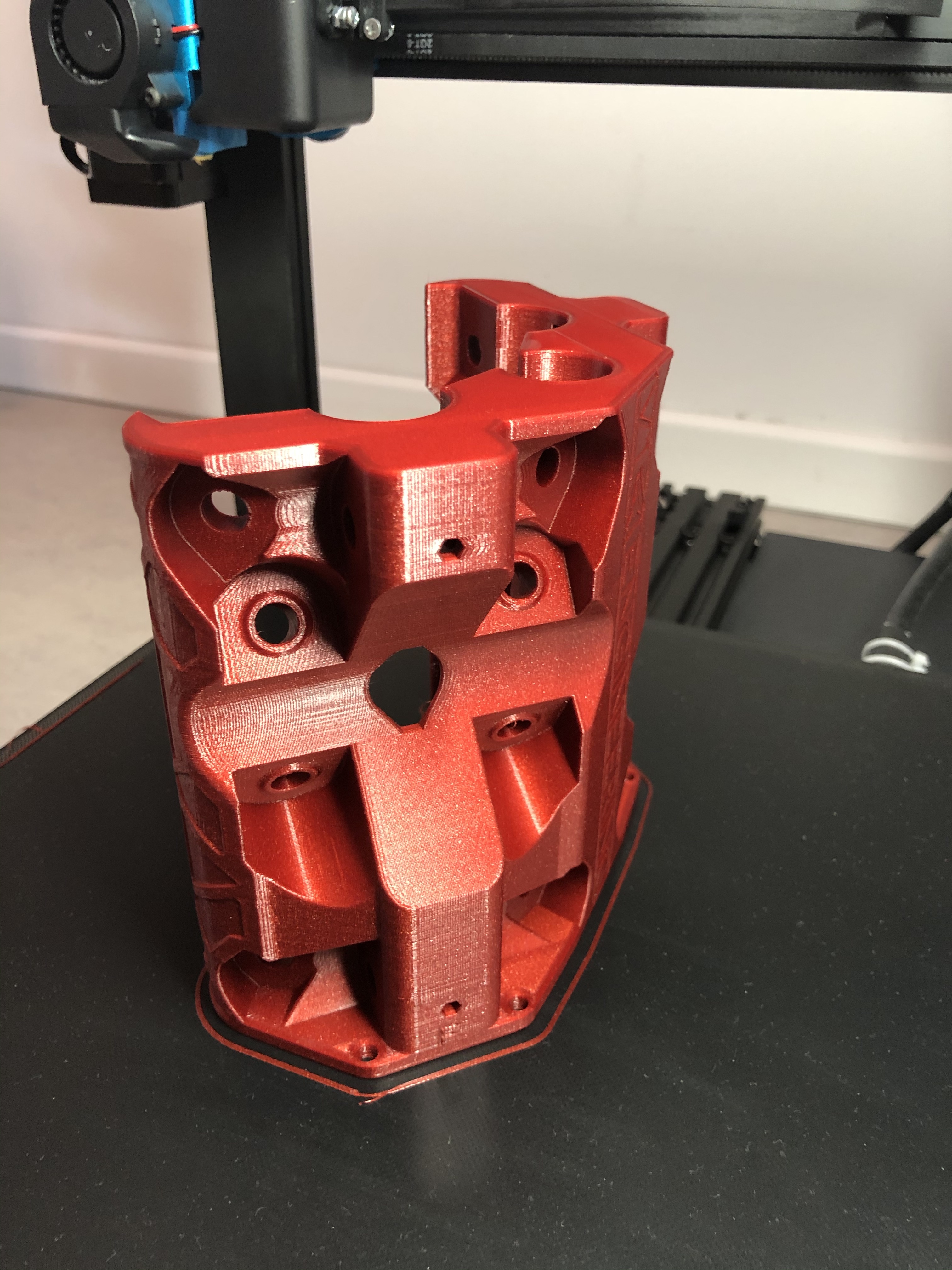
Almost finished printing:


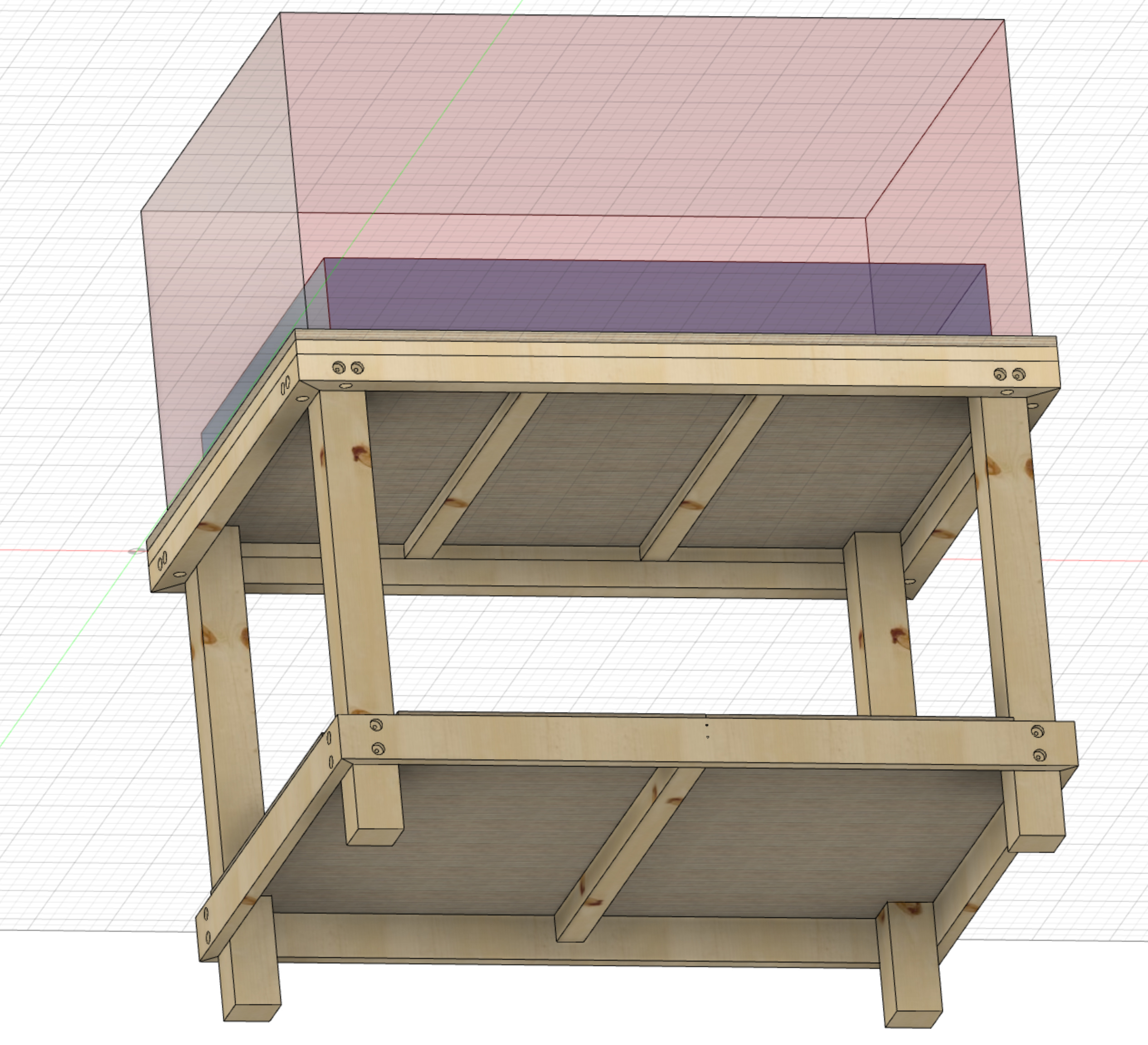
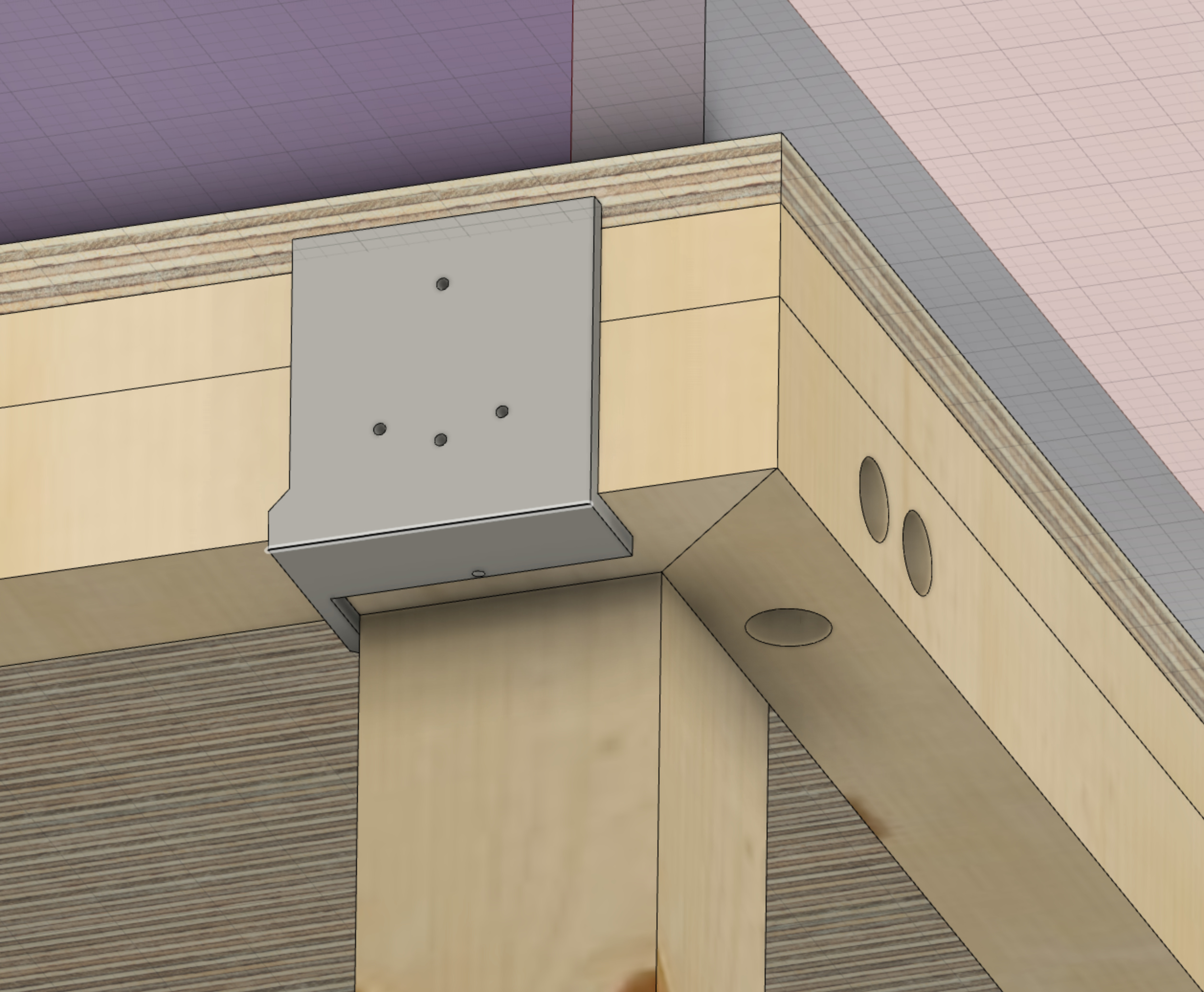
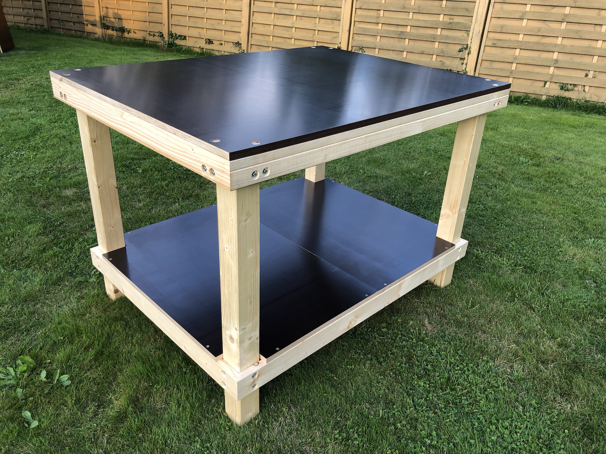
Last week I designed a machine table to meet my requirement to be transportable in a car and to withstand several dis- and assemblies. The latter I achieved with M6 thread screws, nuts and threaded sockets. The red quadrant is the machine footprint (height not accurate) and the blue one is the outer feet edge size.

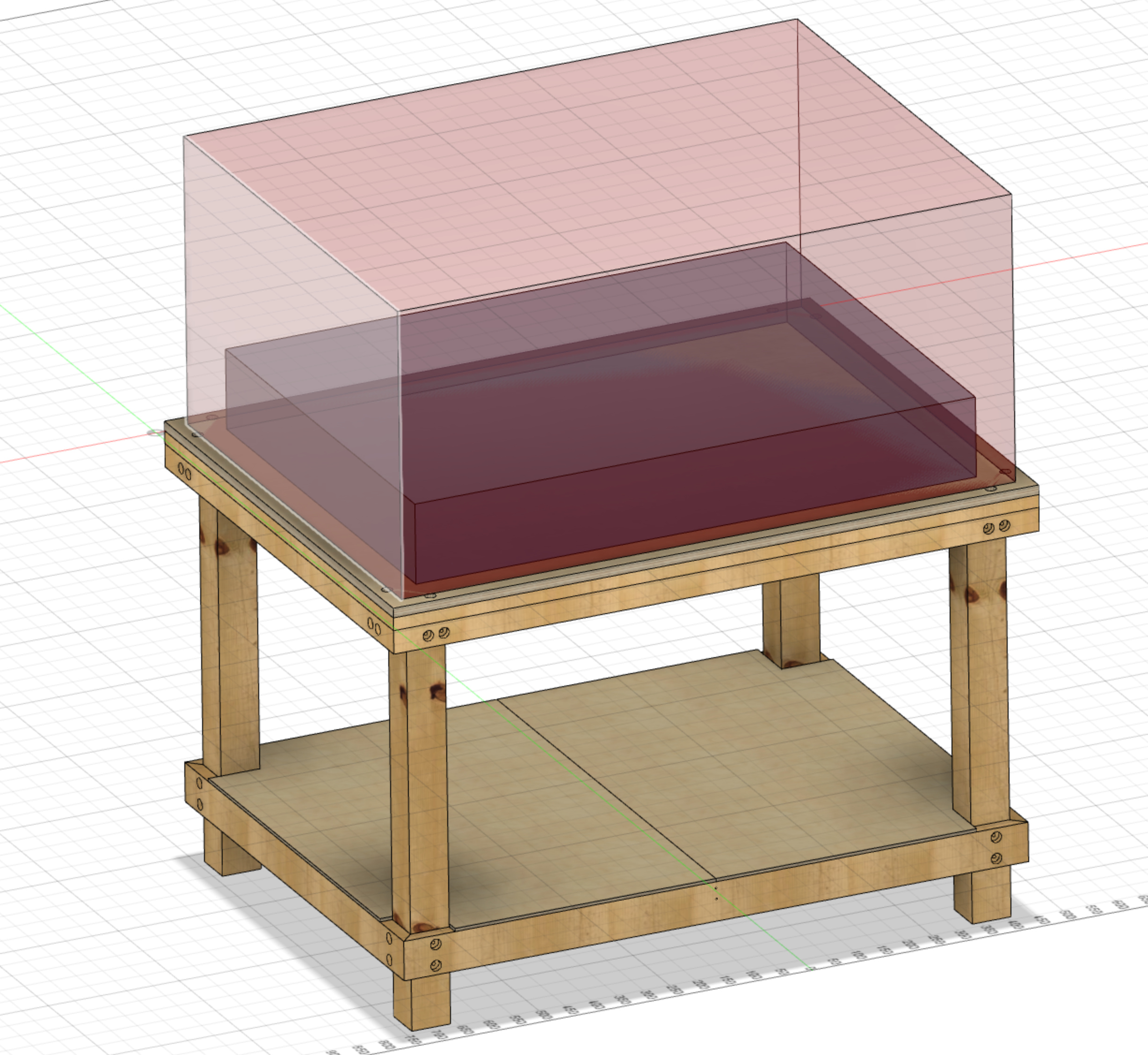
The table top is screwed to a frame to avoid bending and torsion of the 18mm “Siebdruck” plate. This part can easily be lifted and moved without the need of the lower table construction. I left additional space on the table top for an enclosure.

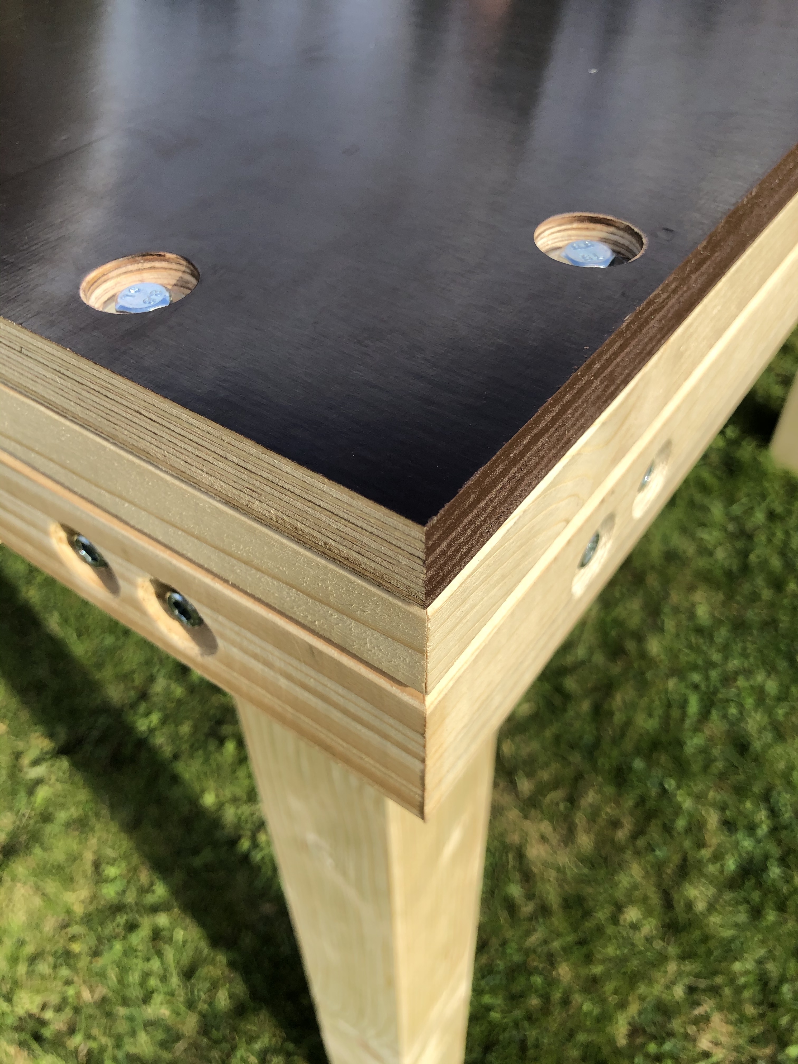
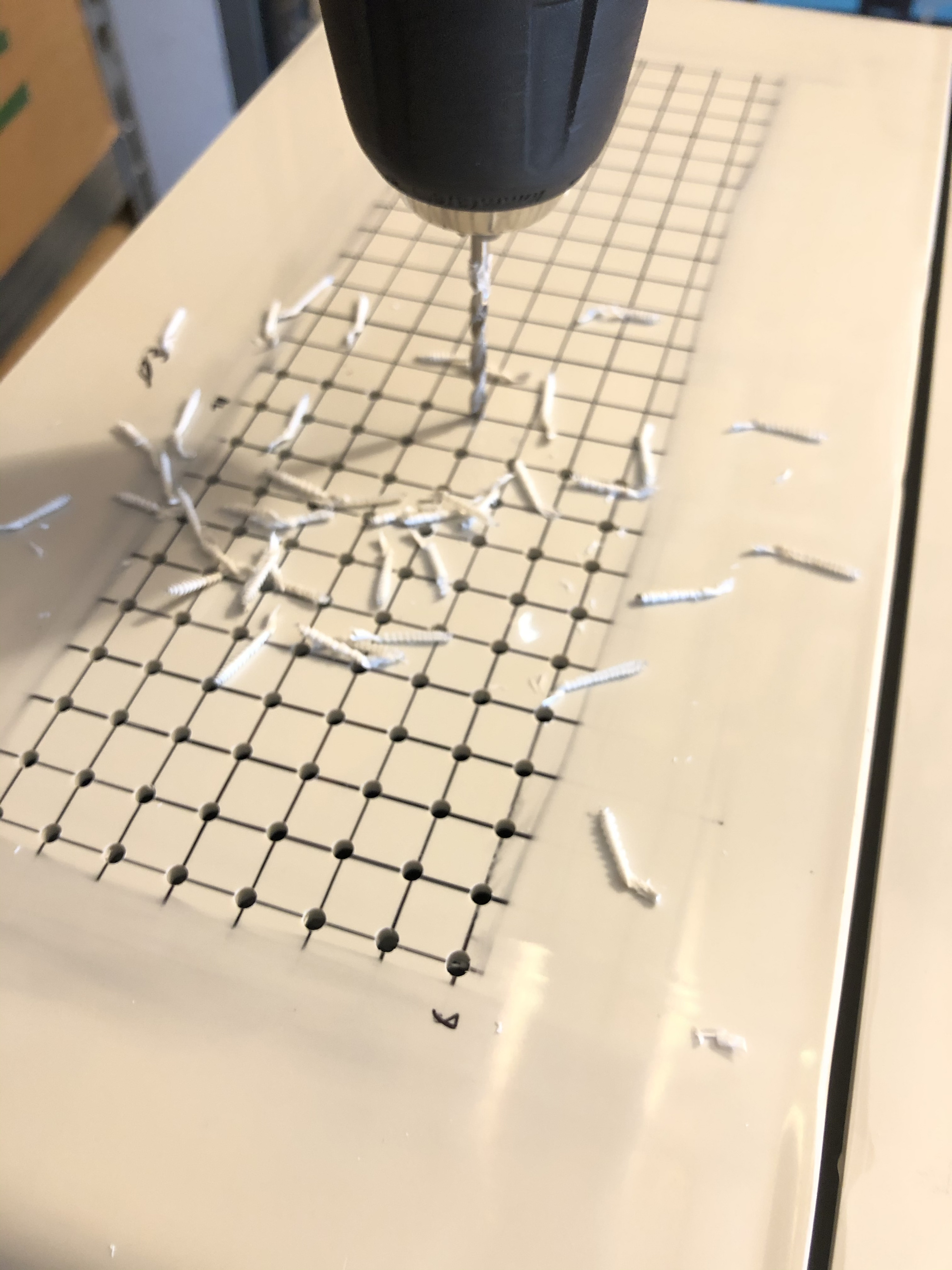
I also printed a drilling template to save a lot of time and avoid measuring errors.

The hardest thing is to get the 100% accurate computer models where all fits together to a tangible thing and actually build it. But in the end it turned out very well, thanks to the templates I think:

So far so good, I am looking forward to assemble the Primo. But first, the table must be completed.

16 Likes

That’s a beautiful build. Love the maroon filament. Looking forward to the rest of the build!

2 Likes

Sehr schön! :smiley:
Very nice build and documentation so far.

2 Likes

Finished the table today (Size: 1232x941mm):

Total table costs were around 120€
A cheap spoil board (e.g MDF) is planned to be added on top. Threaded sockets will be embedded in the black wooden slab.

9 Likes

I am always envious of the German black multiplex. It’s pretty cool. Most of our melamine has particle board core in the large hardware stores. It’s harder to get the big sheets of this.

1 Like

It looks neat, but it is really expensive. I thought about buying it as well but decided against it. It’s getting dirty anyway. :smiley:

Actually “Siebdruck” was cheaper than regular multiplex slabs. Custom cut regular multiplex is 56,73 per m2 whereas a full slab of 2500x1250mm “Siebdruck” is 21,99 per m2.

see:

https://www.bauhaus.info/multiplexplatten/multiplexplatte-nach-mass/p/14453677
vs.
https://www.bauhaus.info/siebdruckplatten/siebdruckplatte-fixmass/p/20396831

3 Likes

The table looks like a beauty!

1 Like

Hello again, I’m lay-outing the control cabinet at the moment. Does anyone have thoughts or recommendations?

The box will be positioned vertically, so the VFD will be at the top.
The main airflow goes from left to right. (Fan pushes air inside), holes will be at the fan side, the opposite wall at the top side.

Upper right area is planned for SSRs, while the right side wall is used for connectors. The VFD will get an aluminum sheet enclosure as a shielding.

3 Likes

Quite some progress today:
I finished soldering the main PCB. In addition I grounded the spindle motor which hasn’t been done by factory (Rattm Motor 0.8kW, water cooled). I double checked the grounding with my multimeter.

Moreover I was drawing some grid lines for the fan inlet. Same procedure for the outlet which I moved to the top of the case to avoid any heat build-up. Clearance to the table is assured.

Top air outlet:

Controlbox:

I’ve calculated the total hole area of each of the two openings to achieve that the upper outlet is smaller than the side inlet.
Im hoping to get some minimal positive pressure by the fan to avoid dust from the top the fall in the control box. Consequently I’ve increased the bore diameter of the side inlet holes to get a higher inlet area with less holes compared to the top outlet area.

2 Likes

Ah… the sweet smell of Teutonic (over) engineering… :wink: Love it!

2 Likes

Time for an update:
The cable management of the worktable has been finished. Final step is to cut the wires to the right length and solder the plugs.

I designed my own cable chain mounts for a 50x30mm aluminum L profile extrusion:

Then I designed a clutch to attach the end of the energy chain to the respective truck. The first attempt for X came out good, but I recognized that I lost a few centimeters of X-workspace. So I redesigned the mount for the X-axis and in the end I simply used the mirrored frame mount from the Y-axis. I added some zip tie holes to fasten some of the cables.

One requirement for the Z-axis mount was that the cable chain should be directly attached to the static core in order to reduce load from the Z-motor (spindle weight already 2.95kg). Works well!


Next steps:

  • wire the control box
  • installing relays
  • programming the VFD
7 Likes

It’s alive! I’m proud to present my almost finished first ever CNC.

The control box is set up, tested and only needs some fine tuning of the Inverter settings.

During first power up I recognized a broken DRV8825 driver which resulted in one stepper behaving strange. I was troubleshooting the issue, swapped motors (no change), changed the stepper cable dupont direction (no change), swapped the driver (error moved to other stepper motor) and finally exchanged the whole defective driver which solved the mystery.

At the moment, both 230V sockets will be powered once the spindle runs. Thats why the upper solid state relay is not connected. I consider it as a spare until I have better ideas what to use it for.

I nearly turned insane when I was the soldering the GX16 connectors. I frequently forgot to put on heat shrink or the enclosure having already soldered the ports to the wire… still getting angry thinking about that disaster haha. In the end it worked out, but I recognized that I missed to shorten some of the stepper wires to the same length. Nevermind.

Concerning the water cooling, I use an IKEA 22l Samla box, a 25W water pump (JAIYAOCHENG) with 10L distilled water but NO antifreeze. Before using the demineralized water, I rinsed the whole system with normal water, since there might be dirt in the spindle cooling system. So far no leakage :slight_smile: 
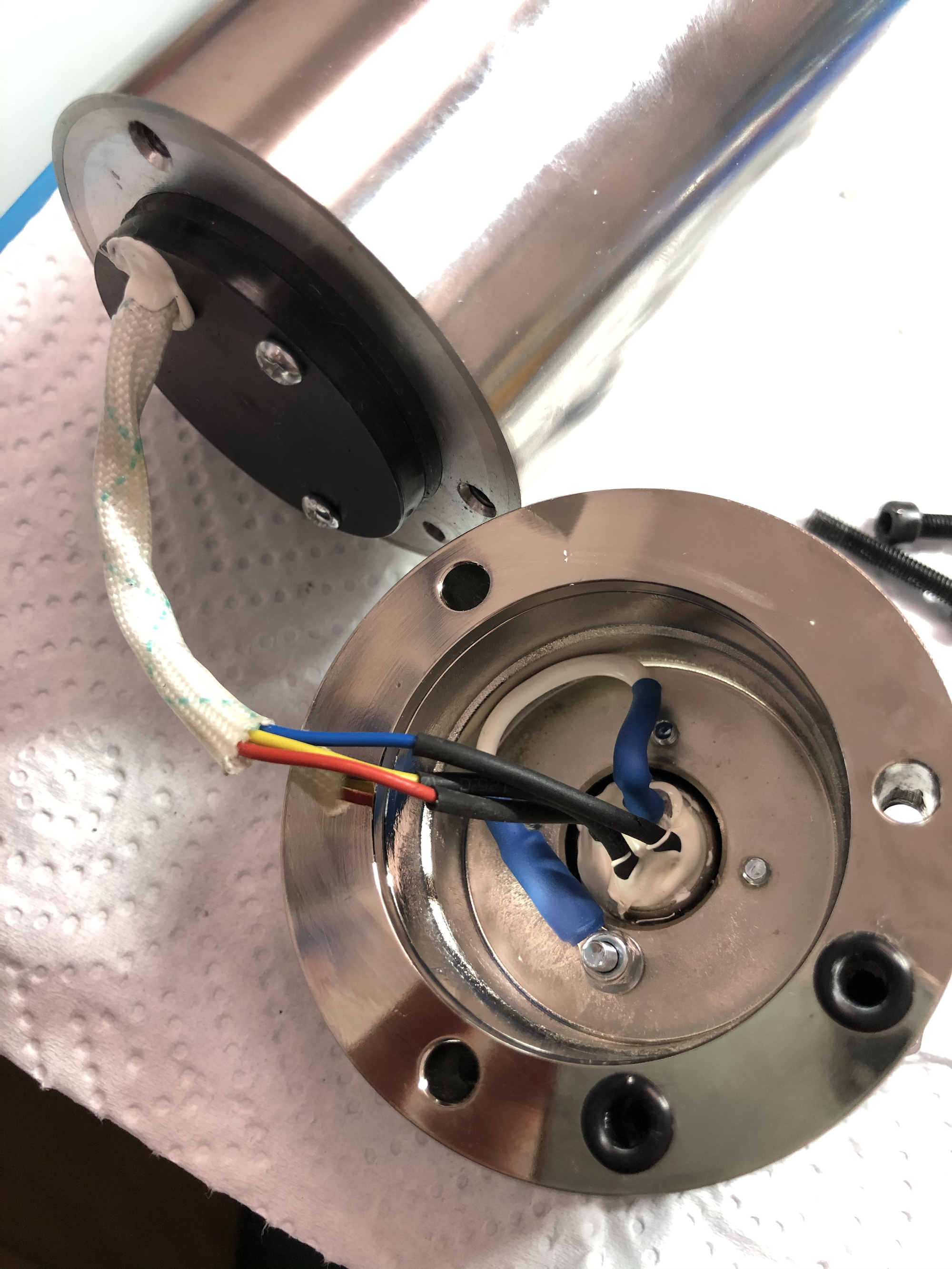
but I got a few oily spots on the water surface, so good to have it washed.

Since I didn’t find an adequate pump grommet (“Tülle”) I designed one that fits to the pump and into the PVC hose with an inner diameter of 6mm.

I think I will upload the described mounts to thingiverse soon, to support other builders.

I’m hoping to start the calibration drawings soon and then getting dirty…

So far thanks @vicious1, it was a pleasure!


11 Likes

Stop making the rest of us look bad! :stuck_out_tongue: 
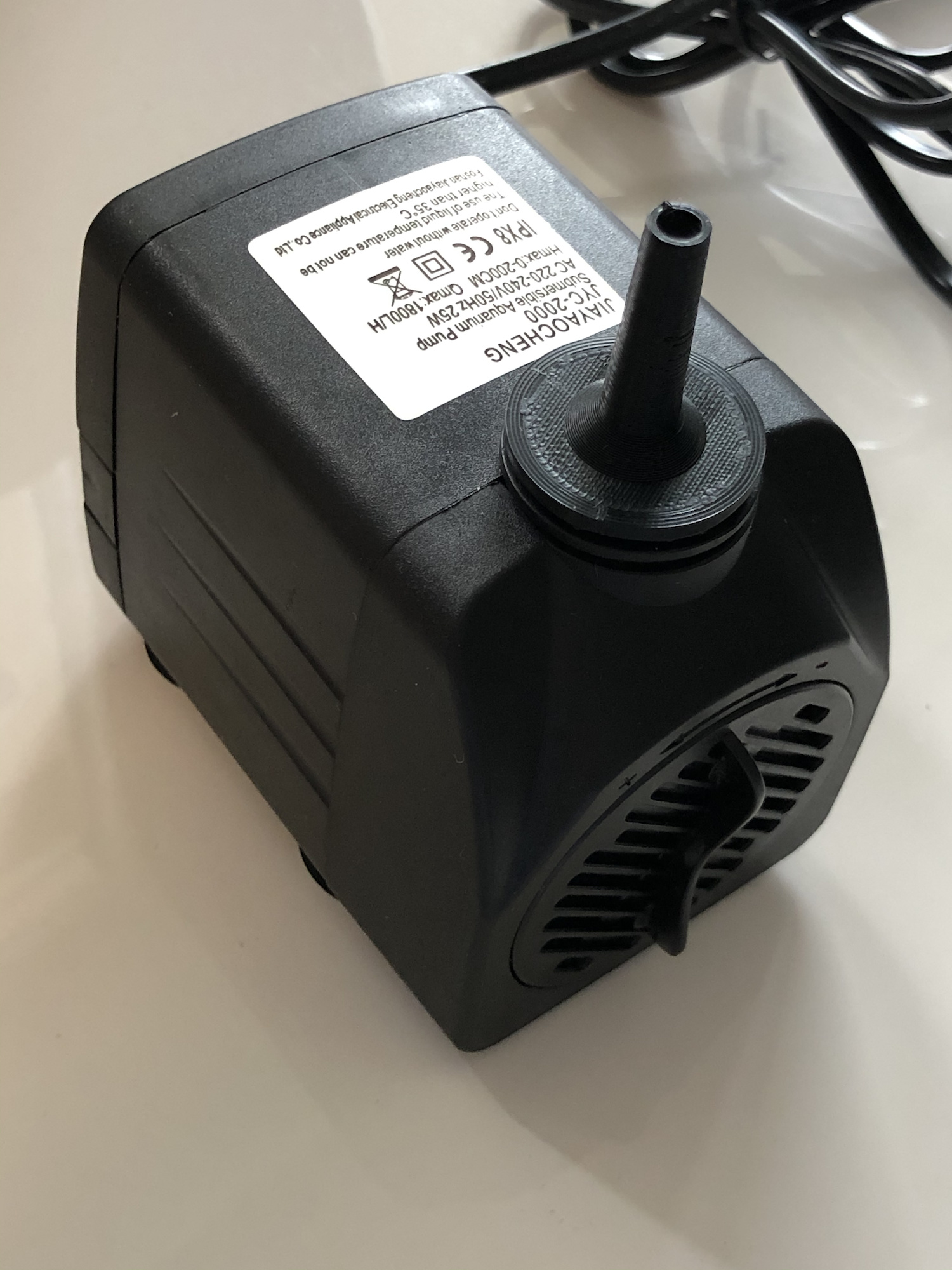
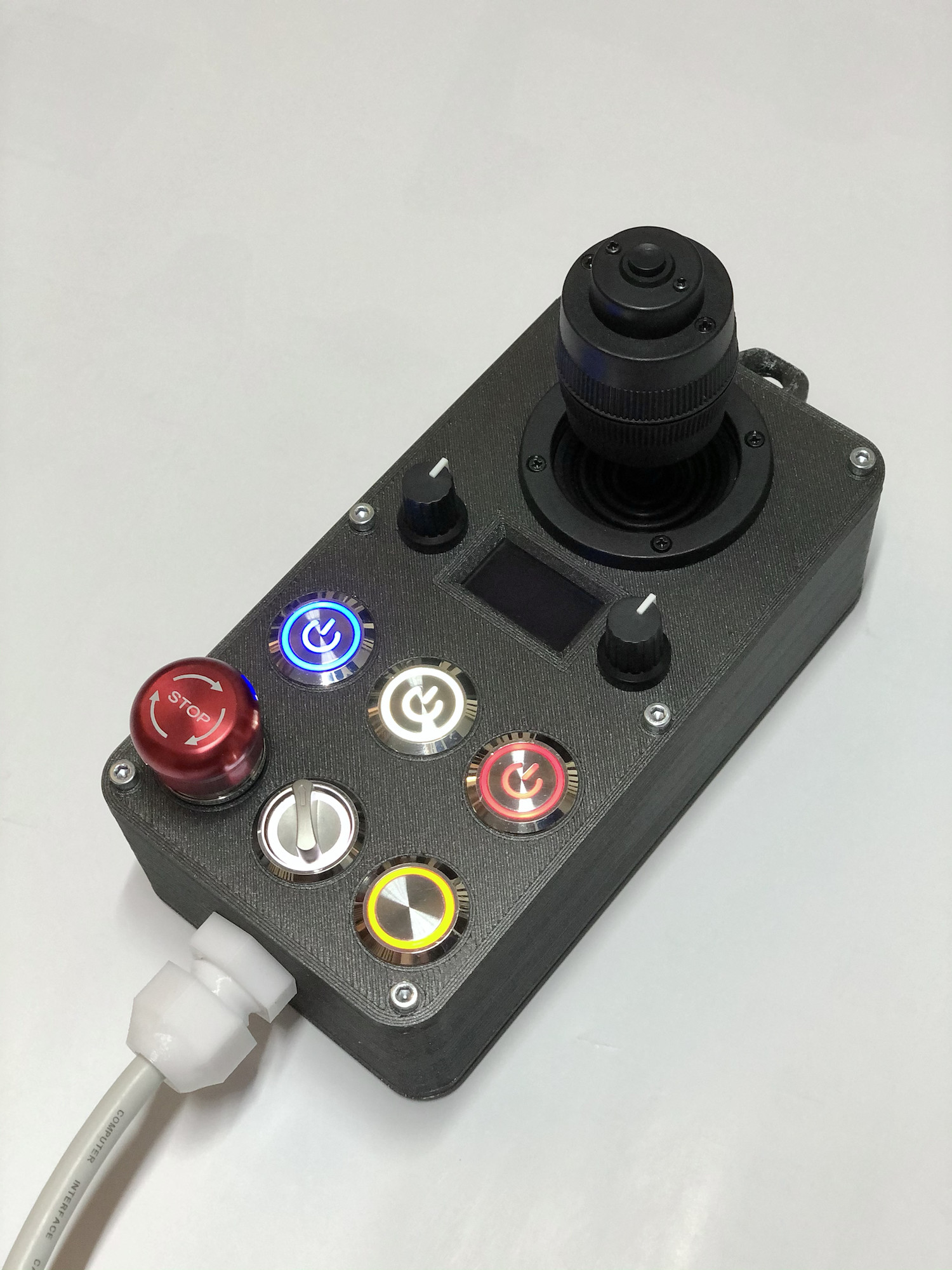
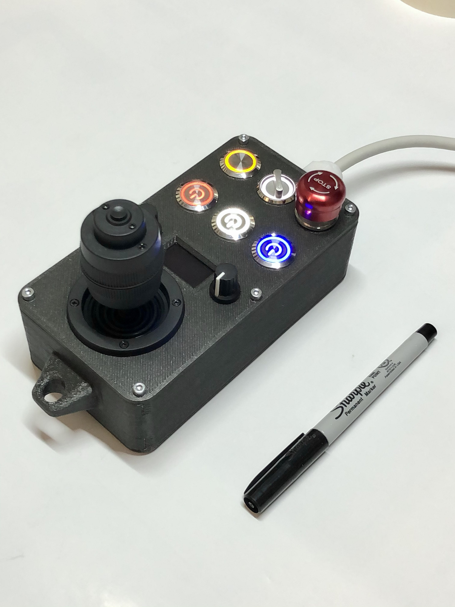
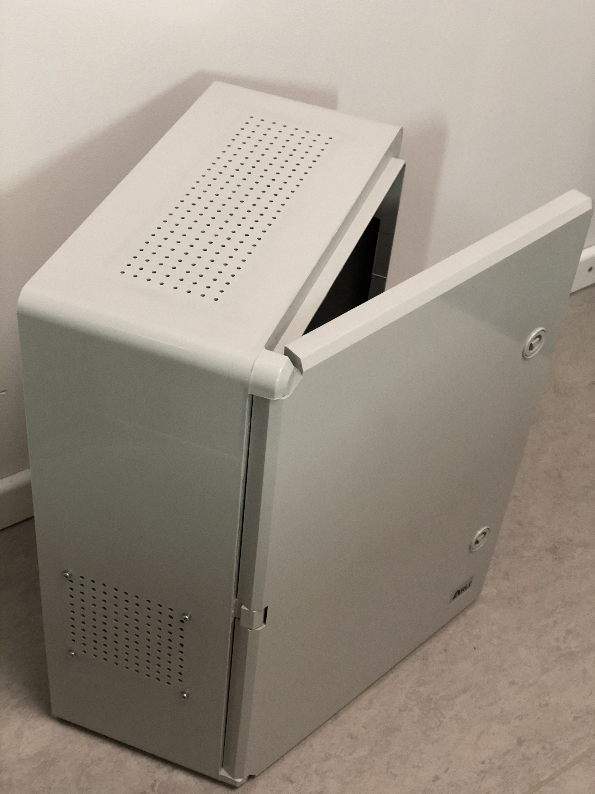
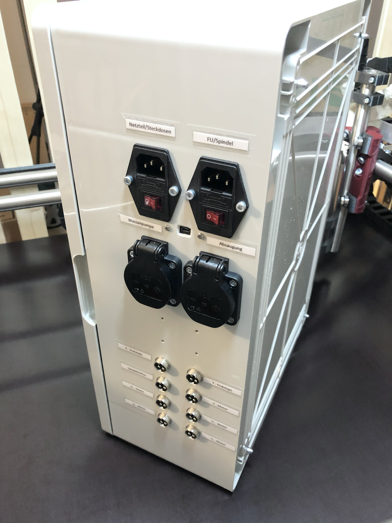
That control box looks so great.

2 Likes

The STL files for the mounts or the grommet can be found here:

Absolute monster…now get it dirty!

3 Likes

Baby lock the door and turn the lights down low… :notes:

I worked a few weeks on a self-made hand wheel for my MPCNC that has still no proper name.

The switches colors’ make their function self explanatory:
blue for air, red for danger, white for program related

  1. blue PWR= vacuum cleaner start/stop (or later maybe liquid cooling)
  2. white PWR = program start/stop
  3. white 3 position switch: control estlcam speeds for the joystick
  4. red PWR = spindle start/stop
  5. orange = initiate autosquare
  6. e-stop = stepper motors cutoff (spindle and electronic box remain powered, not sure if that’s the best option, but I haven’t spend deep thoughts on e-stops yet)

The display doesn’t function yet due to compatibility problems. It will present information about the autoquare status and the water temperature of the spindle cooling. I also added a handle to hang the controller somewhere if unused. The two potentiometers adjust the feed rate and spindle RPM.

12 Likes

that is very impressive! where can i get one?

1 Like

Thanks @Atom.

I uploaded it to thingi: https://www.thingiverse.com/thing:4721882 with a parts list.

1 Like

Do the German Wal-Marts have an industrial Enclosures aisle or is electrical engineering part of their primary school curriculum?

2 Likes