I’ve been gathering parts and had the best of intentions, but my time is getting crunched and I’m wanting to show something for the effort. I wanted the cleanest setup and the most organized wire setup, but I think the reality is now I just want it to work. I built a control box Saturday… I used a piece of wood a little too thick for the laser and it burned the edges, but everything in there seems to work and is fastened down. I can remake it later, though that is probably unlikely.
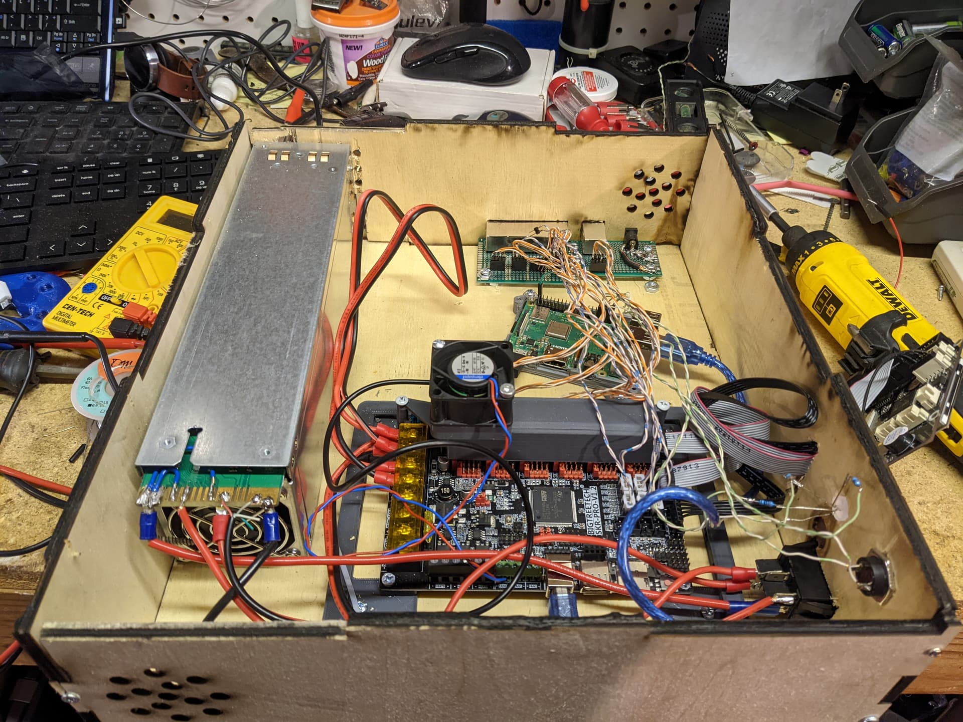
The left-side cover is missing for the testing and the photo. The top is the right side shown in the picture.
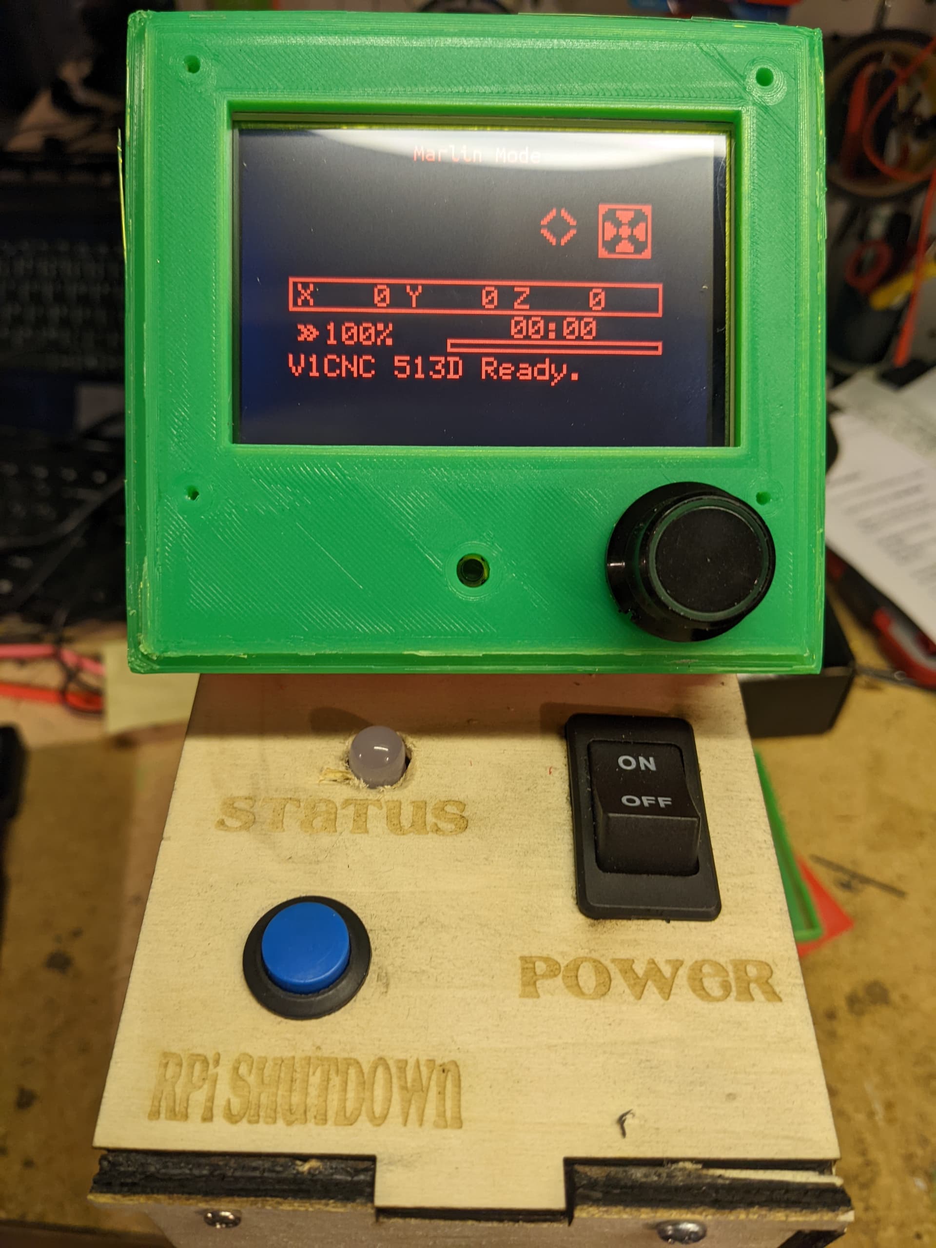
The rpi is a 3b and has a power button for shutdown using the overlay and a pull-up resistor on pin 21. The mounted skr has a 12v fan wired to the cooling tunnel mounted over the tmr2209 modules. Power comes from an hp blade server supply that puts out 19 amps at 12 volts and 5 volts for the raspberry pi that is also switched with a rocker on the top panel. The raspberry pi runs octopi. the board in the back is a salvaged 5 port ethernet setup for cable connections to the motors. The top of the control box has the power rocker, the momentary pi shutoff, and an rgb led indicator that is controlled by an octopi “rgbledcontrol” plugin. The box is to be mounted on the left side of the table with the screen mounted next to the home position on the top edge on a printed part that is not yet finished. The LED wiring is still exposed in this photo as well, but that won’t be left out flapping in the breeze.
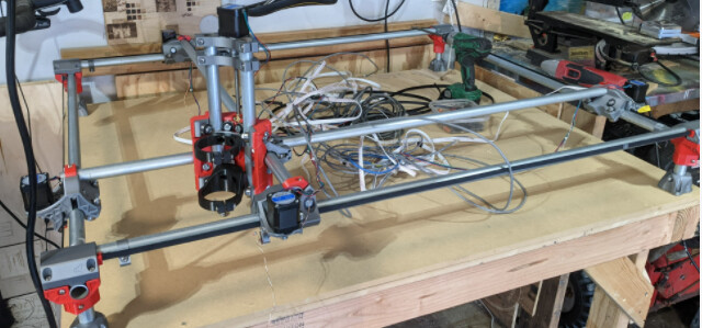
This is the system so far:
Table was built last week. Stands are aligned and mounted. Just printed tube mounts for the drag chain.
Remaining:
Drag chains and mounts are ready to put on and the wiring that goes into the drag chain needs to be replaced with stranded wires and it is still 30 degrees in the garage, so the work there has been slow and limited, but it is taking shape.
Dust collection printed parts and hose mount for movement still need to be considered and printed or fabricated.
Hopefully in the next 2 weeks I’ll get that sorted out and installed. (edit: added links for printed parts)
Looking nice so far! I like how much room you left in the electronics box - I usually don’t plan ahead quite enough and wind up having to cram things in after the fact. Repurposing Ethernet / RJ45 for the motor wiring is a nice touch also.
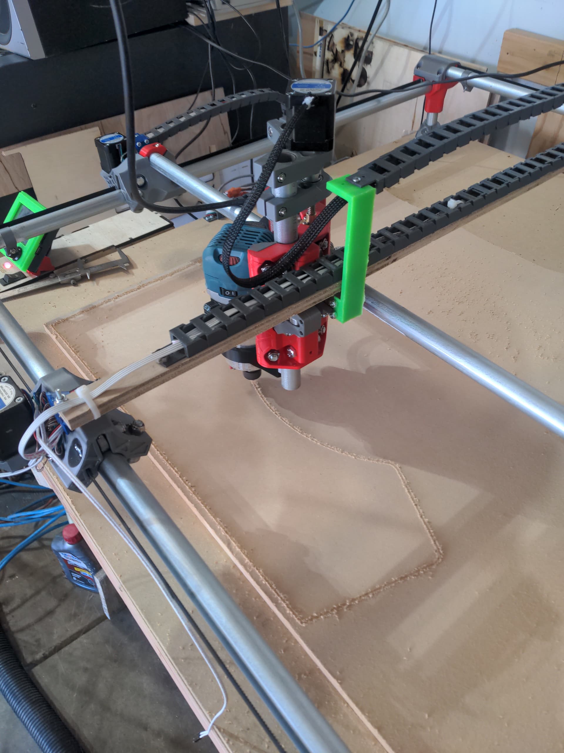
Have not yet “run” it, but it is assembled and it moves and homes in the correct direction.
(wire hanging off the right is for the z probe)
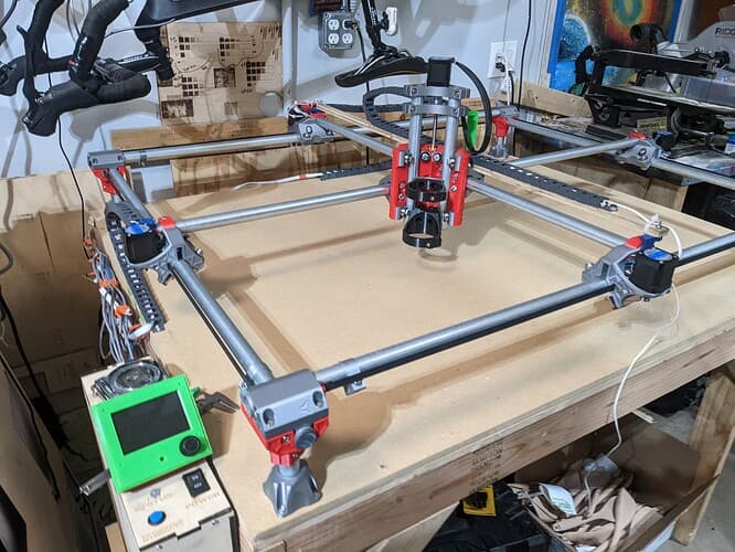
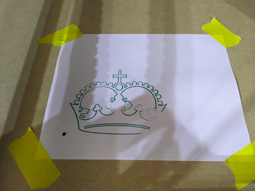
It is a bit multicolored because of printer filament supply… numerous failed prints. I’m currently printing a pen mount to draw the crown and start processing gcode.
With every intention at the start of making it pretty, after a few weeks of upgrading the 3D printer and fighting with it, the shift to function over form took priority. If it cuts, the produced items won’t care what color the LCD screen bezel was or if the cable drag chain was mounted to the motor or the tubing… whether or not I resorted to electrical tape to try and keep things straight.
The MPCNC is 30" x40" cut area and I’m into it about $550 because I had all the wood laying around and already had a spare raspberry pi and an electrician friend donated the EMT. It cost me a roll of TPU filament for a friend to print my silver and red pieces, so that cut my costs considerably. It would be about $700 if I put cash out for everything.
The steppers are not energized until they are first moved electronically. It is possible they are de-energized at the end of the job, or at the end of the timer set in the firmware. This will depend on your firmware settings and on the settings of the software you are using to send the g-code. For me, when the steppers are energized, they are strong enough that I don’t lose steps using a wrench to change bits, but I can definitely overpower the holding force if I want to.
With your larger cutting area, you might consider mid-span supports on the outer rails.