Looking at the pieces, the drag chain mounts are optional, correct? They aren’t structural to the core support?
Yes, that’s correct. I have added them only because if you normally use drag chain mounts they might be too low.
For the core support they are not necessary.
My son printed the 3 core_clamp_F_primo parts, as well as the two blocks and the corner piece that you designed. I received my order of bearings, threaded rod etc. yesterday.
So I’m trying to get my head around the 3 core clamps. I can see that one will be used for the corner block (the piece you have circled above in the picture). And one will replace the “core y” clamp that has the notch out of it.
But I can’t figure out where the third core clamp is used.
Maybe an overhead picture of the whole assembly would help my understanding?
Thanks!
Hi @BonzDarrell
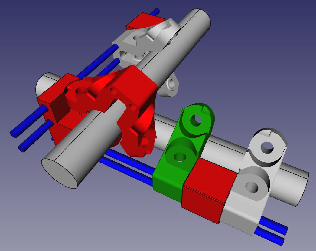
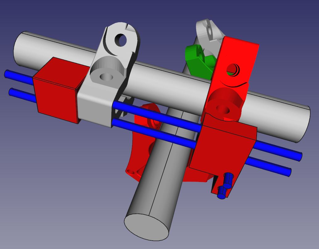
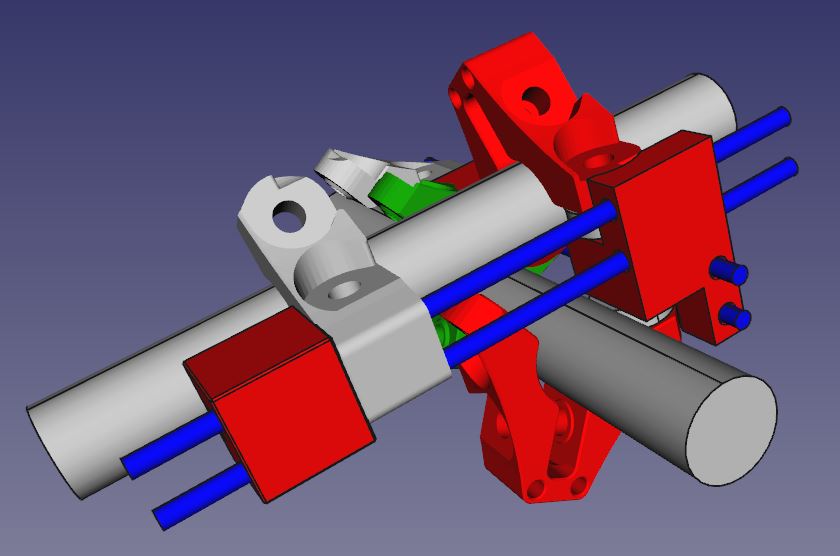
sorry for the delay. Here some shots of the CAD system. Red coloured are the parts of the adjustment, green is the clamp that was replaced.
So you can see, that both clamps are connected to the center part, one on top, the other from the bottom, holding/guiding the center part.

Hope that helps.
Ciao
DJ
1 Like
Thanks DJ! That makes more sense. After work today I’ll head out to my shop and get this assembled.
Thanks!
Hi @DJPicasso
This idea is amazing. I have only one concern: How much stress/pressure will receive the center part?
How is your precision and stability after this? Will this help to reduce shattering and vibrations?
Hi @josedgm
you needn’t to be concerned. The pressure to the center part is less than you think. But, of course, you need to consider, that the area you can precise the angle of x- and y-axis is probably about 88° to 92°, not more. If your angle is out of this area you should check your general construction.
To be honest, I am using a number of different ways for precision, stability, reducing vibrations etc.
- this tool to precise the angle of x- and y-axis
- the center part and the additional clamps for the precision
- the “cubes” between the clamps for stability. These cubes are helping a lot to stabilize the core and the clamps, really a big advantage!
- additionally my control supports autosquaring (electronically) so the angle is exactly 90°. After building the MPCNC I had - mechanically - an angle of ca. 91° and with the tool I got exactly 90°. Using the autosquaring func this tool is mostly for stability.
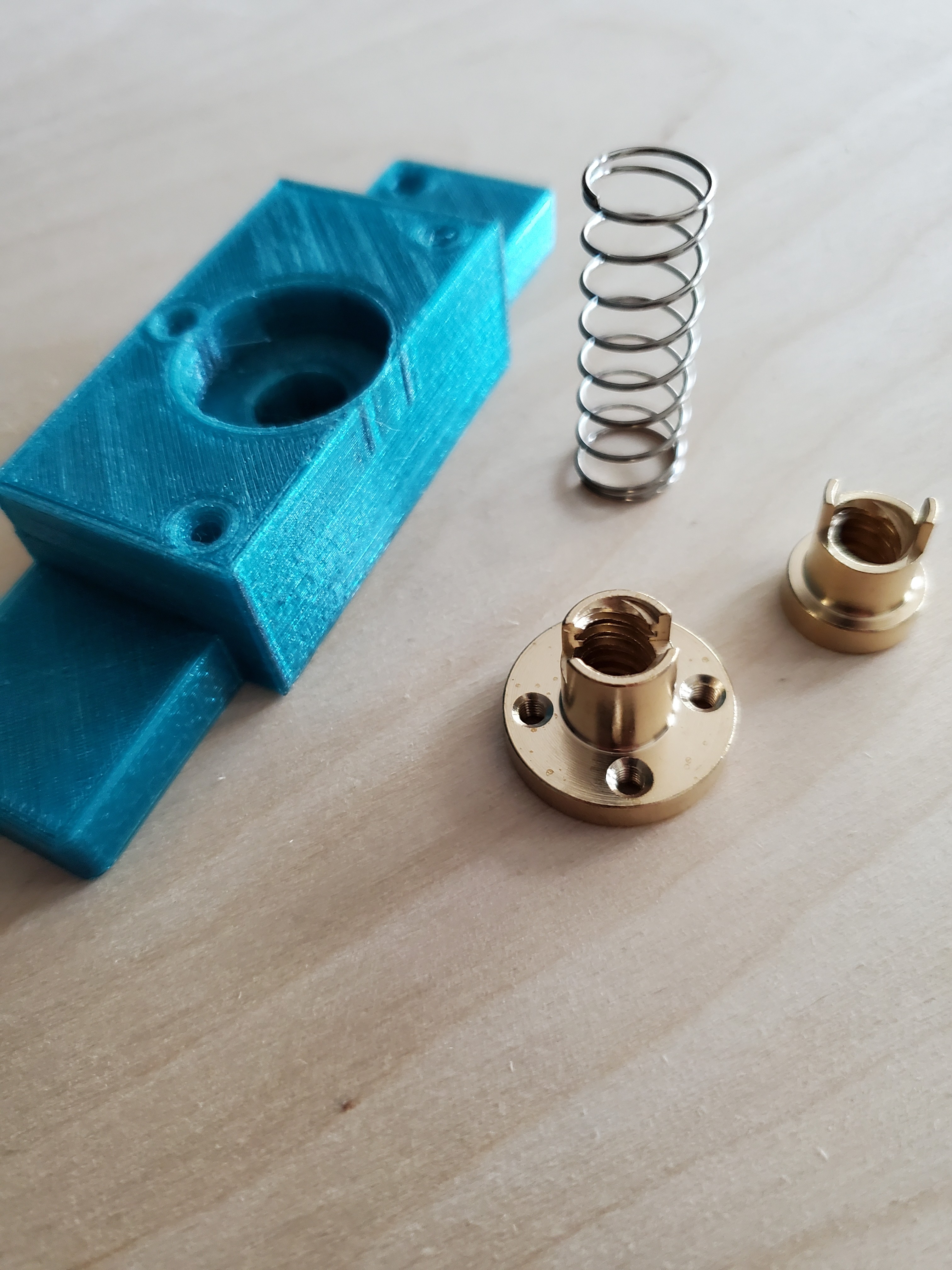
- additional clamping block for a thread rod nut (anti backlash nut) - this really reduces vibrations! I mentioned it here: Solving Z axis lifting problems, stepper losses
- I printed the MPCNC with stronger material: mostly CPE HP100 and ASA - really a huge difference to the standard PLA!
Ciao DJ
I tested out the core-adjustment-tool today…
After installing, I was able to tweak my assembly just a tiny bit, so it’s really, really square now. It seems stiffer as well.
As a side note, I forgot to re-tighten the clamps holding on the router, so my first 30 seconds of cutting was done at about 3mm with no apparent problems. I usually mill at 1.28mm DOC and want to be able to bump it up to 2.0mm - this accidental test seems to show that a 2mm cut in baltic birch should be feasible.
I took a video, but can’t figure out how to post it here. Maybe I’ll add it in on FB group…
Hi @BonzDarrell
sounds good! So the parts fit for the 25.4mm version. As mentioned above, with the cubes between the clamps the construction gets much more stability!
You should also test the additional clamping block with a anti backlash nut mentioned above! 
It is a “small” add-on, but you will be surprised about the difference!
With my construction I mill up to 5mm DOC in aluminium and feedrates up to 800mm/min (trochoidal) without problems.
It is available also on Thingiverse now
1 Like
Thanks DJ - I read about the z-axis mod, this looks very interesting.
I wasn’t clear whether you re-printed the core with extra holes?
I’m not familiar with an anti-backlash nut, I’ll have to look that up.
I didn’t spot a link to the file, did you post that to thingyverse?
No, I printed the standard core using the standard holes.
Posted it
Challenge accepted to do it without. ![]()
![]()
Currently passing Oldenburg once a week, next time next Monday ![]()
If it wasn’t for Corona I’d invite you over. 
In summer I will stop over for a beer
1 Like
My son printed my core stabilizer thingy…
This weekend I’ll probably add this, add the center supports and increase my Y axis by 3".
Hello, nice job.
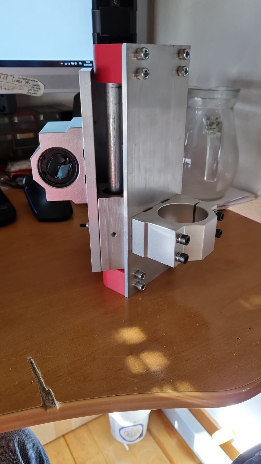
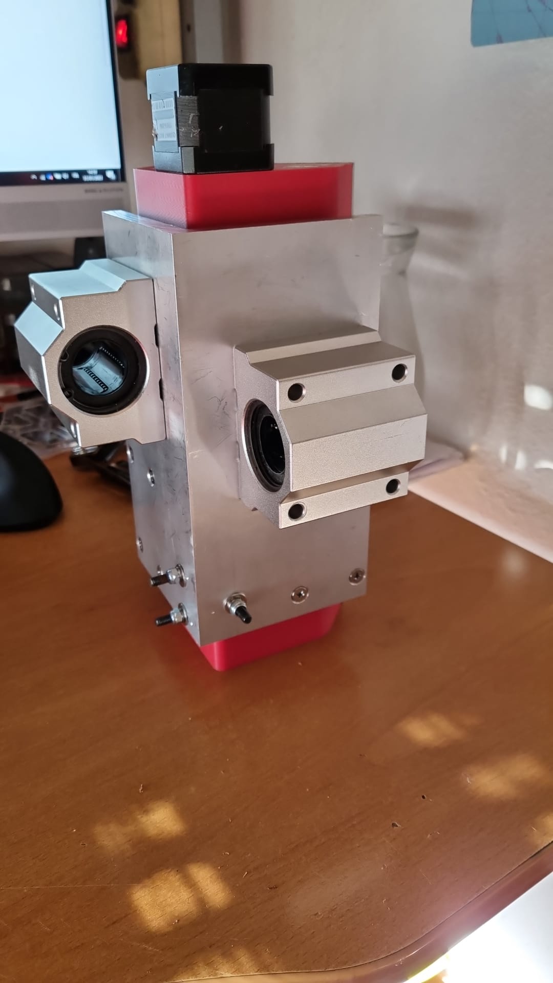
I want to share my upgrade too… i had the mpcnc burly, great machine. But some time ago i’ve started thinkering about a “mostly alluminium core”. The primo core is nice but it involves too much print time for me. here some pictures of my new core.
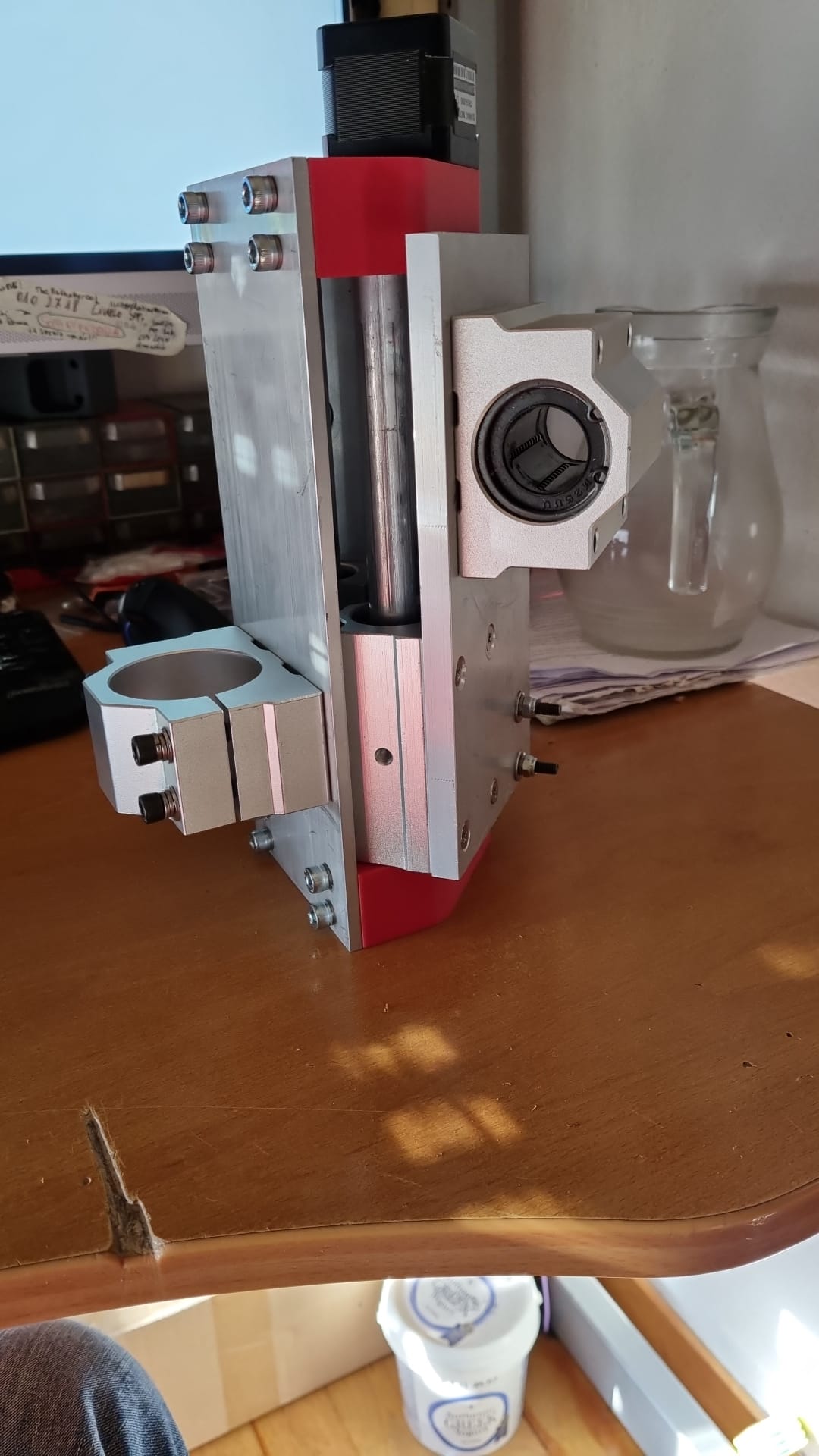
1 Like
Yo, you didn’t stop over. ![]()
Shit, forgot! ![]()
Passed Oldenburg more than 30 times in the last 2 years.
Will try to do it this year … you need to remember me some time
We did it and met up, was nice! Thanks for visiting. ![]()
1 Like