Hi! Would love some input!
I have a hard time to engage all bearings towards the z-rails when tightening the core clamps.
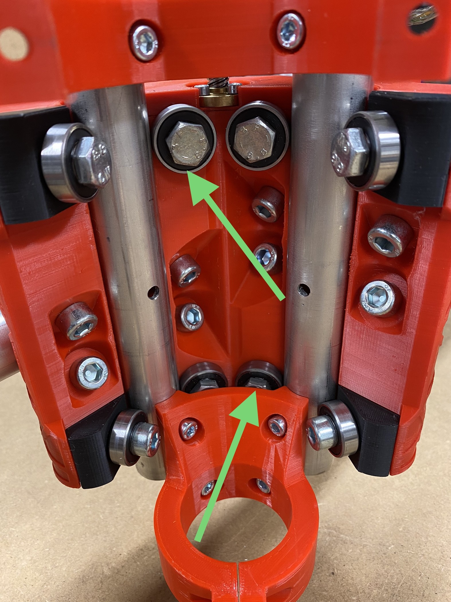
Please see the image for which bearings that is still loose/not touching the rails.
I’ve tried to following the instructions point by point.
Any ideas what/if is wrong?
It looks to me like you’ve got y our Z tubes out of square.
Try loosening the screws to the tool holder, and on the Z tower a little. Something is forcing those tubes to have a skew towards the left (in the photo) causing one to exert too much pressure against the tightening nut on the top left and the one on the bottom right. Let the Z tubes float a touch in the tower clamps and then you should be able to tighten those 2 clamps to bring them into square and perpendicular. Don’t use a lot of pressure! Once those are done, you can make the tower clamps and the tool holder clamps snug but not overtight. Too much force on any of these bolts makes everything worse.
Another thing to check is that tool mount. Primo mounts should all be using my spacers to make them the same size, universal. If those are indeed Primo mounts, and designed not to use my spacers than make sure they are the right size as the three versions would need unique mounts to fit.
The wrong one would certainly space your Z tubes incorrectly.
I tried to just push down a single rail in the left slot to see if i could clamp that one independently of the other. But even if I tight down the upper clamp to max, I still has a play of ca 0.3mm.
On the right side I can achieve a fit.
Guess that means something is wrong with the print? I did a the basic square test before all prints and it was great though.
It looks like you’re using 1" OD tubing, correct? You may have already checked but it would be worth verifying that the OD of the tube is actually 1" and that you printed the Core for 25.4mm (which is the largest one so that wouldn’t explain it being too big). But atleast rule out any tubing inaccuracies.
Good thinking! It´s actually 25mm stainless, and I’ve checked its dimensions. And the core is the F-version, just dubble checked! Im printing Ryans advance XYZ-test now, will be finished tonight(Sweden). Just to make sure!
Damn frustrating to not be able to go on
Correct! I’m living in europe and 25mm OD is easier to source
Our town had a power outage three times today, so that kind of ruin my 3d-print…
I’ll restart the XYZ-test tomorrow.
Oh okay! Then yes, the F version is the right one. Odd that it is not fitting up well. Has to be some issue in the print. Maybe somehow accidently scaled the part before printing or print characteristics are off in some way. Definitely try to square and calibrate your printer, definitely don’t want to print the core 3 times!
These kinds of assumptions are why Ryan was insisting that you use his spacers.
If that tool mount was made for 23.5mm tubing, or 25.4mm, it would definitely pull the Z rails out of alignment. Given that it seems to be spreading the tubes a bit too far, I’d think that it was for 23.5 conduit.
I found plenty of adjustment available when I was tuning mine (“J” version, but shouldn’t matter) so not being able to get a fit at all seems bizzare to me. I’d bet that I could clamp 25mm and get a fit, even if not the correct one in my core.
Before you go and print another core, I’d really check this one. The Z tubes should ride against the back bearings, and the inside ones, with the outside ones being the adjustment to hold things in tight. (Or so goes my assumption based on the fact that it’s the outer bearings that have that adjustment piece.) Put those bolts in just snug and remove the outer 4 entirely. Inspect the bolt holes for signs of the bolt threads cutting into them or cracking, which might happen if overtightened when things were out of square. Push the bolts/bearings in, and check that they can be pressed against the tubes with your fingers (no nuts on yet.) Check that this does not leave a gap between the core and the black adjustment wedges. Hold them that way, with a rail in place and put the nuts on.
Thanks Dan for your detailed instructions!
I did try to mount the original Ryan tool parts, and followed your instructions. However, only to end up with the same results. No luck, unfortunately!
I also tried again with a single rail, same results.
I´ve started to print a new core, repositioned 90 deg on my build plate(along y axis) to mitigate any potential defects from the original print. Not sure if it is a good idea, however I need to do something…
No it didnt! I agree that this is strange! Which points me even more to a faulty print.
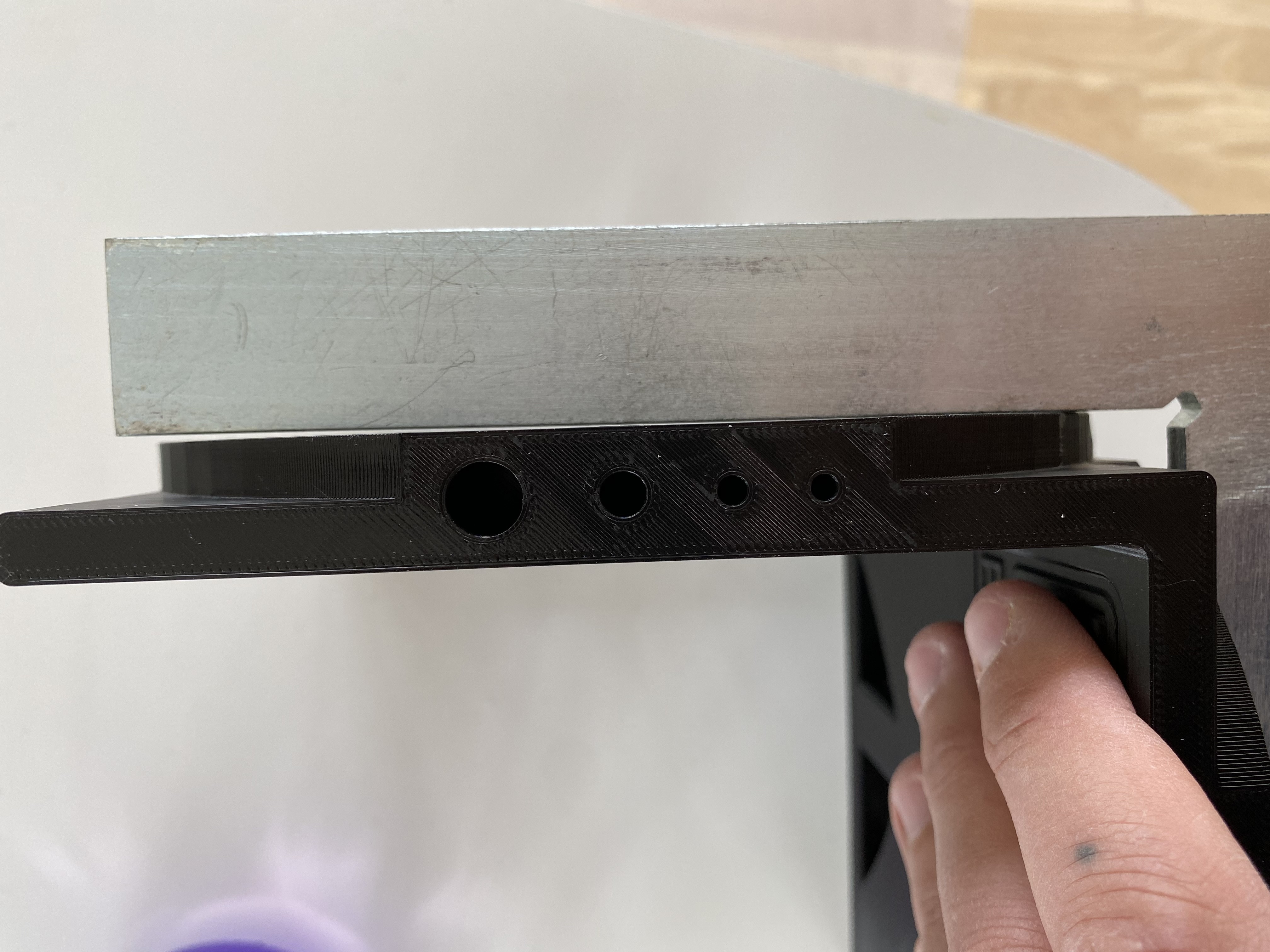
I did print the xzxy teat part and all dimensions is spot on except the to diagonals going from inner bottom towards the outger upper cornera. But they was only of by 0.2-0.3mm.
However it wasnt dead on true 90deg. And a bit worse on the top than bottom. Not sure if this is within the margins? Could be that my z-rails(Ender 3pro) is a bit tilted? That error would multiply at the top of the quite tall core, right?
Obviously this is a user error somehow. But to retain my pride I hope for a faulty print
But still a single rail will work no matter what. It sits on two points top and bottom, the clamps should easily hold it in place with all bearings touching. If that can’t happen a bolt must be really far out of wack.
Try it again and check both sides. That has to work unless it was twisted far enough to see with the naked eye.
Do you have the bearings in the back where we can’t see in the pictures (that has happened before).
Fair question, but yes. All bearings are in place!
Just switched around the clamps/wedges and got a decent fit. But no room to over-tighten it(not that I want to) which means that something is a bit of.
Just being able to close the play between the parts.
Probably not the clamps, most likely I got in a more favorable position this time.
I think I pause here and just wait for my ongoing core print. It is not worth playing around if it turn out to be the print anyway.
I’ll keep you posted! Thanks so far!
Hi guys! The new print worked as it should!
Somehow the first one got skewed but I don’t know how.
Anyhow, Im back to building and hopefully it goes on smoothly from now