Forgive me Ryan for I have sinned. It has been a few months since I last logged into the forum. I have had lustful thoughts about other CNC machines. I have been flirting with Workbee but I eventually took my beloved original MPCNC to pieces to take on the Primo upgrade. I have to say I can appreciate the difference in the design changes. Great Job Ryan. and great job on the improved and updated firmware.
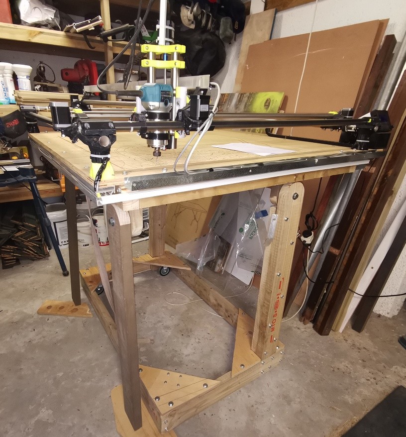
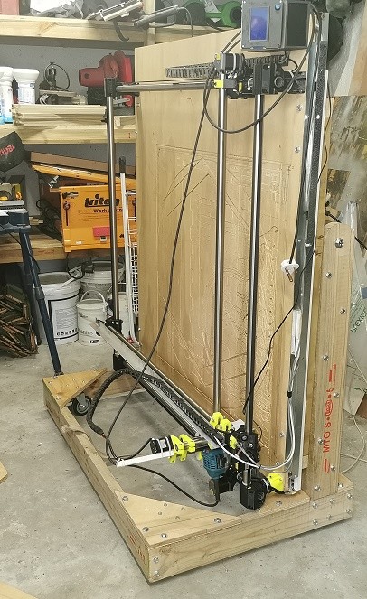
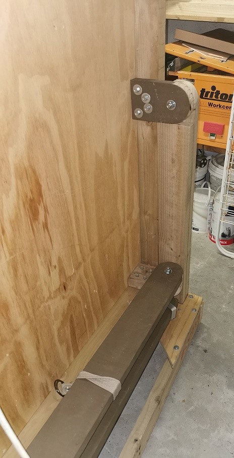
I don’t know why I did not upgrade sooner. Having Auto Z height is just so much more civilized. My 61 year old eyes and back not up to setting manual Z height so well anymore as well as having the dual limits for squaring up. I have put the new MPCNC Primo on a fold up table to make it possible to be moved around and out of harms way when big things are being moved around the garage so resquaring each time it is set up is important.
My queries that I would appreciate some guidance on.
I am using a Ramps 1.6 board with A4988 drivers with LCD & SD Card reader as that is what I had in my box of bits - I use SD card to transfer files from the PC to the MPCNC. Firmware is V1CNC_Ramps_Dual_2.0.7.2
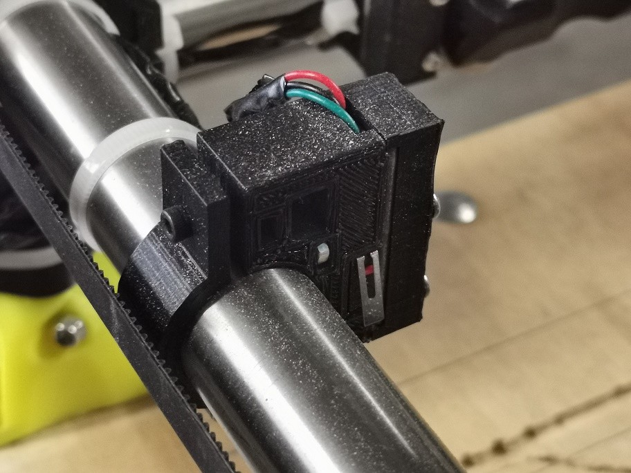
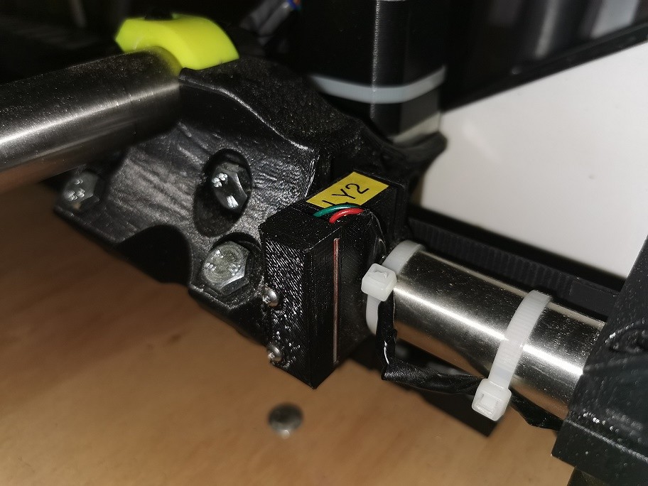
I had to invert the limits setting as I used some 3 wire boards that I had and printed some Thingiverse housings for them.
1 - even though I programmed the Arduino #define DEFAULT_AXIS_STEPS_PER_UNIT { 100, 100, 400, 100 } as I read in the forum as necessary using A4988 instead of your recommended DRV8825 I was still getting the 920mm travel as 460mm.
After doubting myself and reburning the Arduino a few times blaming the programming process, I eventually came across a way to set the sizes through the lcd menu which rectified the issue. Did I miss a step that updates the Arduino? I have not tried anything in the menus to do with EEPROM as I do not fully understand the consequences of that. I thought changes in the firmware would take precedence.
2 - How do I set the firmware offset for Z for the 3mm aluminium flat bar Spacer I am using to set the Material height? Each post I read says use the Gcode, but I like the V1 menu option to home Z so would like to set it in Firmware.
The only possibility I can find in the Marlin firmware is #define NOZZLE_TO_PROBE_OFFSET { 0, 0, -3 } does that look right or am I off the mark? Got nothing to do with a nozzle. Is there a better way to do it in Firmware without having to add it through estlcam? OR is there another way to enter it through the LCD again?
Sorry if these are silly questions, but I have been trawling through the forum for the past 2 days and not finding the answers for myself.
I have got everything working nicely and very chuffed. 920mm x 920mm work area with 1300.5mm and 1301.5 diagonals so as close to square as is practical. Not checked the Z axis for square yet though but it eyeballs about right. 1mm skew I think is very good over that sort of distance.
Do I need to put my measurements into the firmware for #IF Enabled (Skew Correction) or can I leave it as you have set it as default 282.8427124766? Are there any consequences for leaving it as is? Less is more (The less I mess around the more likely it will work)
Sorry for all the questions. Advice much appreciated from those that have gone before me and already worked it out.