Printer tests and calibration

There seems to be a lot of print issues these days. I am going to try and find some suitable tests to help prevent a lot of wasted time and plastic.

1-XY axis distance and square.

You are looking for 150mm on each side and equal diagonal dimensions.
Possible issues, Measure near the top of the print so you are not dealing with elephants foot.

https://www.prusaprinters.org/prints/36412-xy-size-and-square-calibration-print

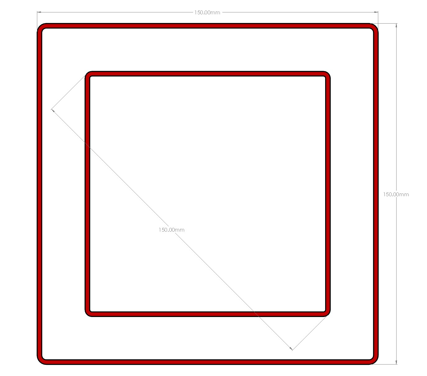
If the outer print is not 150mm - <0.6mm+/- loose (or tight) belts can be an issue. If it is >0.6mm+/- off steps per mm should be calibrated.

If the diagonals are not equal - This means your axes are not square to each other. You will need to physically adjust your printer. There is a marlin tweak to adjust skew but you would be best to get it physically as close as possible first.

Notes- Why rounded corners, accelerations can cause bulging and mess with accuracy. Why 150mm, largest size that fits most common calipers.

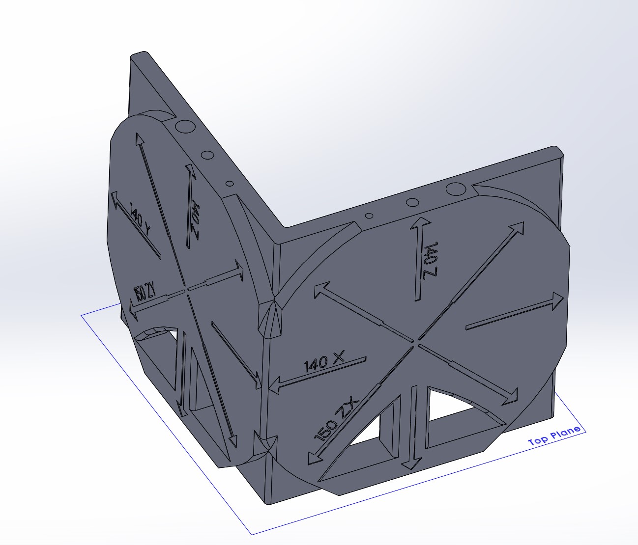
2- ZX and ZY axis distance and square.

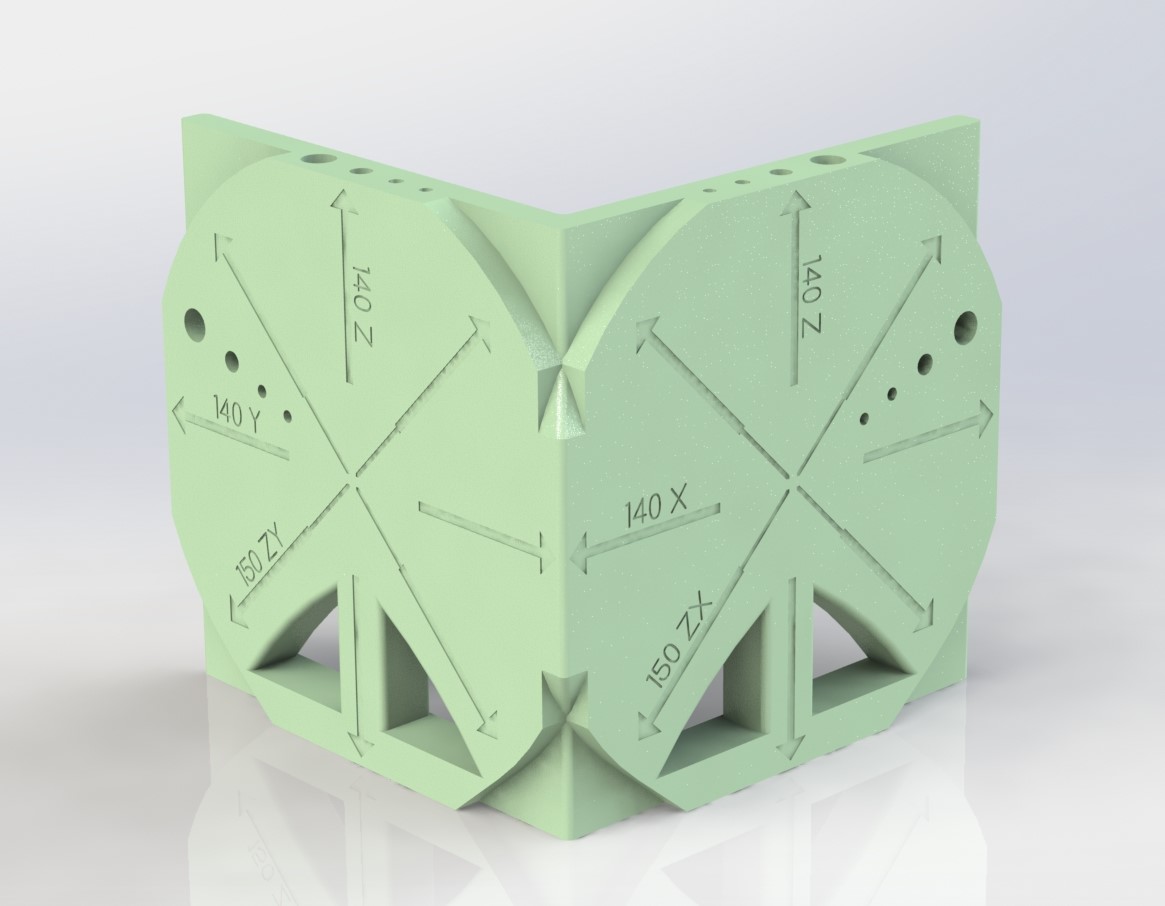
This part is mainly made to test a printers frame for axes perpendicularity. If your printer is built without checking you can get odd shaped prints. Parts that need dimensional accuracy depend on a correctly built printer.

XZXY - main test part.

The Z dimension should be within 0.5mm. Ideally it should be within less than half your first layer thickness, to account for some layer squish.

The diagonal dimensions should be within 0.6mm. This is the meat of this test part. Note; On a Cartesian style build if you find ZY issues you should print a test part on each side of the bed to check both sides of the frame (or Z rails on a Z axis bed build).

The holes are fairly V1 Engineering specific, 8.2mm for bolt holes, 5.2mm for M5 screw holes, 3.4mm for loose M3 screws, 3mm for M3 screw threaded holes. Just a gauge really.

The overhang test should be easy, if not your print temps or print fan is off. These need to work for a V1 Design to print well.

Ghosting of the logo of other designs in the part means you are printing to fast of have harsh accelerations. Good rule of thumb is to see no more than three very subtle ghosts preferably less, any more and you really need to work on that.

https://www.prusaprinters.org/prints/38846-zx-and-zy-printer-frame-test

8 Likes

Suggestion: The small square might need diagonals in the model itself or it will easily flex diagonally and an accurate measurement will be challenging. Unless I guess if you measured it while it was still on the printer.

1 Like

Before I go chasing wild geese, is there a guide somewhere that shows what needs to be changed if the diagonals are off?

I’m within 0.4mm on the outer square in both directions but about 0.8mm under on one diagonal and 0.3mm over on the other.

Depends on the printer.

Ender 3

I’m just having a little difficulty visualizing what needs to move to correct the diagonals.

I need to add that to the instructions, probably best to specify measure while still on the bed? Taking it off means you could get lost as to the original orientation unless I add some sort of orientation feature.

1.1mm skewed is pretty far for 150mm, most mpcnc’s I think are built to under 1mm over ~700mm. For your ender 3 it means either your Y lower frame is skewed or your Z towers are off a little bit. Measure from the front to the towers to see if they are exact same distance back, for the lower frame measure your diagonals to see if they are the same, you can also measure you Y axis from one side to see if it is the same front and back.

Shoot, looks like I am going to need a ZX, ZY test as well. I have an idea.

For that printer, it’s a hardware fix, have to make sure the Y is square to the X, which require adjusting the eccentric bolts on the rollers.

I’m measuring ~` 0.31mm difference in the distance from the the front of the rails to the Z towers, probably won’t get a chance to adjust and reprint tonight but that seems like enough to cause the issue? I’ll also check the Y axis and reprint the squares by tomorrow sometime.

I don’t plan on upgrading to the PRIMO at least until I can get the burly crying for mercy but it’s a new printer and I may as well get it right.

1 Like

For that type of printer, if the frame isn’t square, it won’t print square. There’s probably some kind of software fix, but I’m not 100% sure. I’ve only ever had a corexy and a delta printer.

I’ve gotta go out in a bit but will have at it tomorrow and get it as physically square as I’m able and run the calibration print again. There’s likely enough clearance in the bolt holes to get it closer.

2 Likes

I see that this is 7mm high. If i’s either higher or lower than 7mm, what would you look at? Because then I guees something is wonky with your Z?

A separate Z test is needed for real accuracy. If you notice an issue at 7mm your printer is in bad shape and the steps per mm are way off.

Ok, I grabbed the old calipers and checked

Large Square:

Top = 149.74 mm
Right = 149.75 mm
Bottom = 149.73 mm
Left = 149.69 mm

Small rectangle diameter:

Top Left to Bottom Right = 149.80 mm
Top Right to Bottom Left = 149.80 mm

Z-axis.

Large Thickness:

Top = 6,61 mm
Left = 6,65 mm
Right = 6,65 mm
Bottom = 6,64 mm

Small Thickness

Top = 6,77 mm
Left = 6,61 mm
Bottom = 6,71 mm
Right = 6,66 mm

So something is definitly wonky, what should I look into?

I mean the prints themselves looks fine as far as I can tell, they are just off size ways on the small side.

Another consideration:
Google says thermal expansion of PLA is 68 microns per meter per degree C, in other words 0.0068 percent per degree C.

149.8 / 150 is 0.998667 or 0.1333 percent short.

If it were purely thermal shrinkage, 0.1333 percent would require 0.1333/0.0068 = 19.6 degrees C. I would think that extrusion temperature doesn’t matter and thermal shrinkage would appear between the glass transition temperature and room temperature, which is more than 20 degrees.

I’m not saying this is what is happening necessarily but it does complicate the measurement when trying to nail the size exactly.

It’s well within the guidance of 0.6 mm and the diagonals match, so I think you are good.

Well, I still have the problem when I print for instance slide cases for a pi, and it wont, slide that is. The Pi just wont fit into it. And it has me worried for when I will finally start printing my Primo parts that they are just gonna be to small all around and not fit as intended.

I think I probably have something in the box that will let me attach a dial indicator to the gantry. Or maybe just clamp the fixed jaw of a caliper to the gantry and jog the Z axis?

The issue I’m having is two tries and at least one corner of the small square has a zit or two and I doubt I get an accurate measurement.

A regular calibration cube will work for this, that’s kinda what they’re for. Just get one with the axis engraved on it, or sharpie them before removing from the build plate.

Diagonals are good, that is by far the most important part. 0.3 is pretty good, a hair tighter on your belts could bring that in a bit closer but I am not sure.

I started on this yesterday,

Tests
Z Calibration
X Calibration
Y Calibration
XZ diagonals
XY diagonals
40, 45, 50, 55 degree overhangs facing 4 different ways (fan test)
Starting on 8mm bolt loose, 5mm screw loose, 3mm screw tight (same dims as my models). Need to add them to both vertical faces as well.

Any other suggestions to put in there? Should I add a few spikes for retraction or something.

2 Likes