I am using the SkrPro_Dual_2209_2.0.9.2_513, Fusion 360, Guffy’s Marlin Post and my prints are backwards, I tried flipping the X axis wiring, it just tries to print on the other side of X.
Files.zip (730.5 KB)
I am using the SkrPro_Dual_2209_2.0.9.2_513, Fusion 360, Guffy’s Marlin Post and my prints are backwards, I tried flipping the X axis wiring, it just tries to print on the other side of X.
Files.zip (730.5 KB)
Your axis need to be aligned so that you can stand somewhere and:
I’m guessing one of those is swapped. You also need to make sure you put the origin in the same place in fusion as your 0,0,0 on your workspace.
it just tries to print on the other side of X.
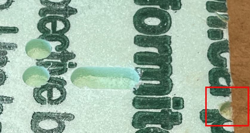
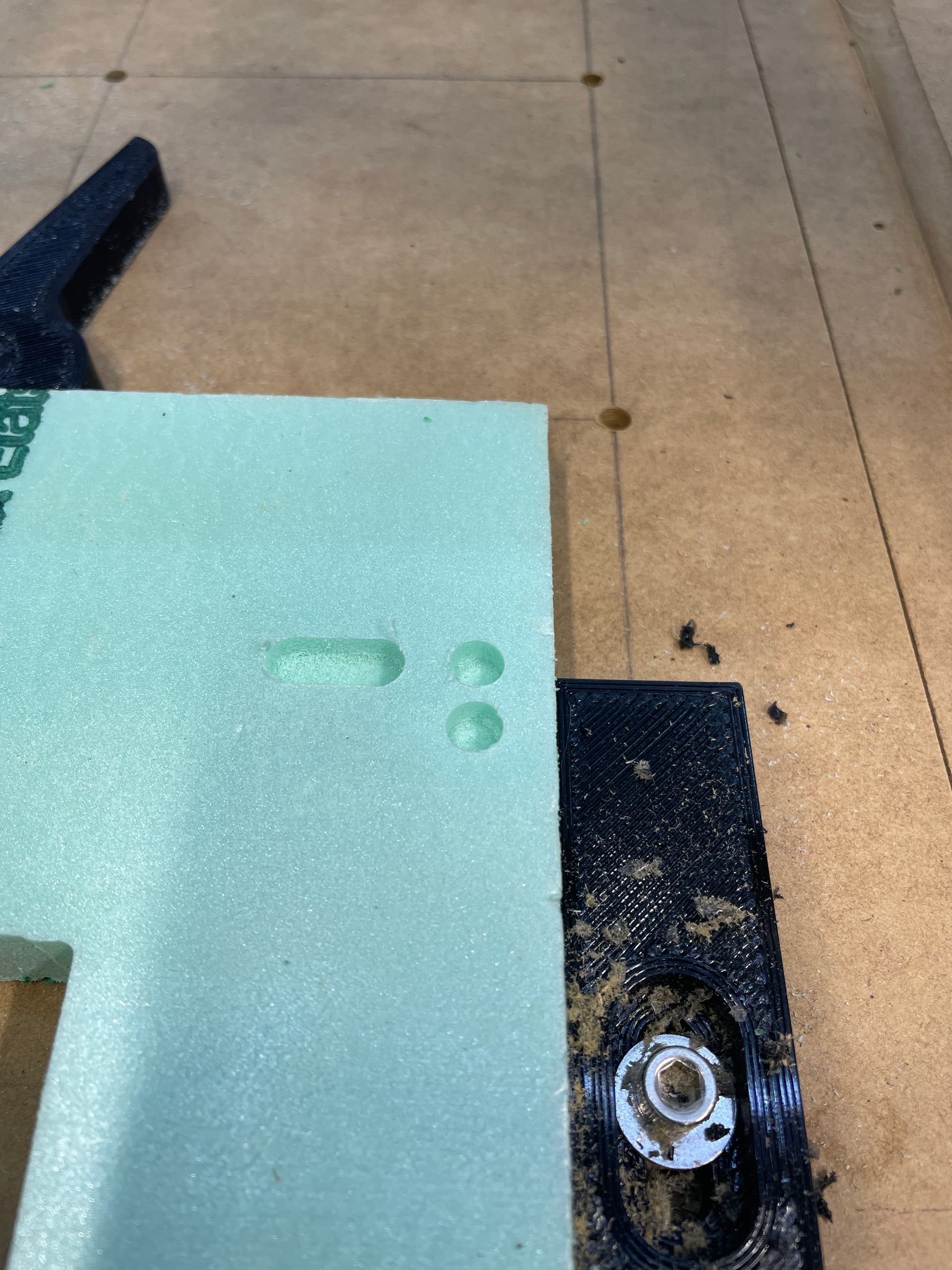
Without a clear reference, it is hard for me to be certain, but I believe printing on the other side of X is exactly what you want. From your picture.
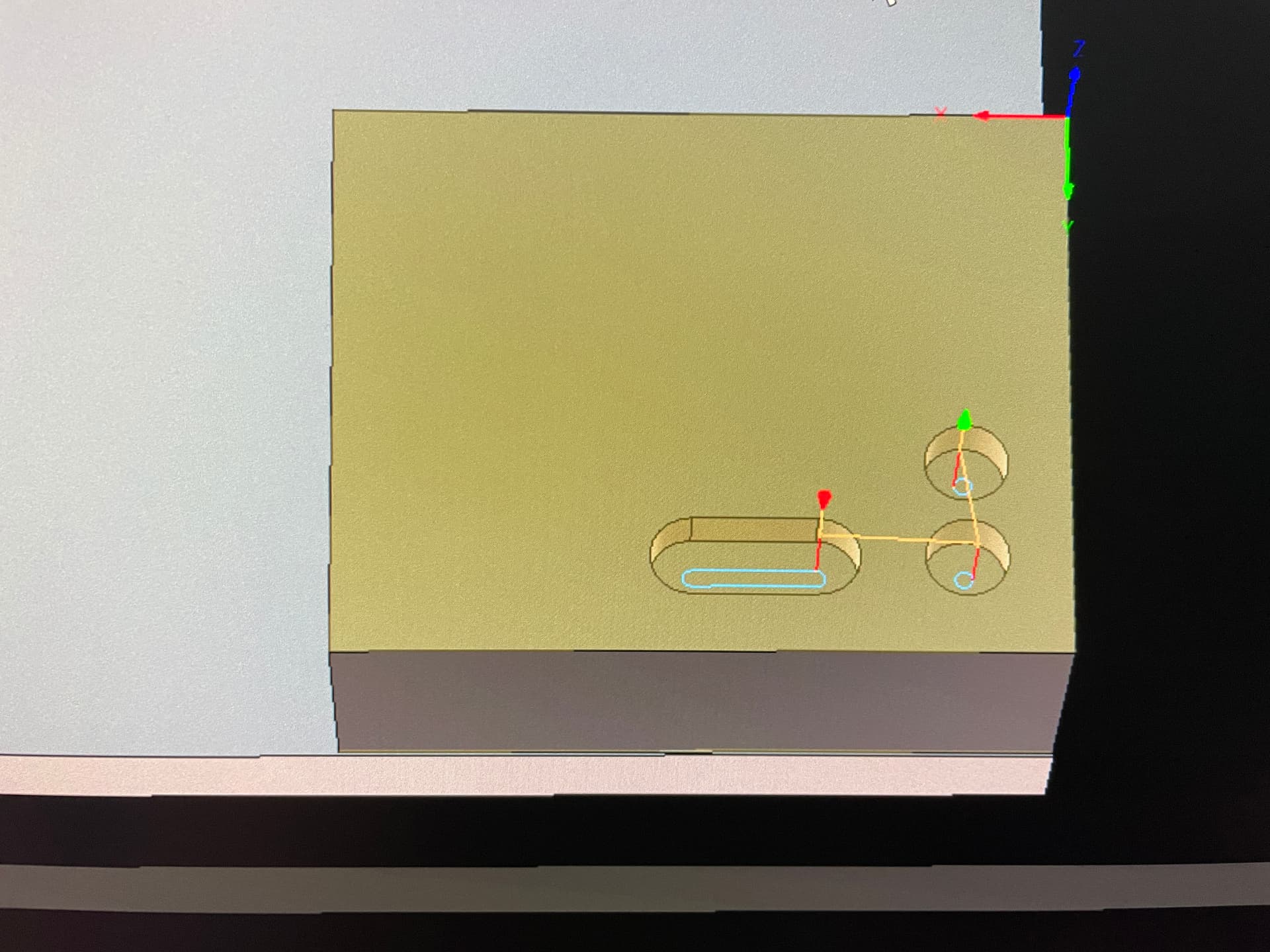
Assuming the dent in the red square is the start position for your job, and that X is horizontal in this picture, if you reran your file with the X axis wiring flipped and used the same start position, I would expect all cutting to be to the right of this point…and that would be correct based on the g-code. Your g-code, as well as your picture from Fusion 360, have your start position in the lower left.
My X goes to the Left as the end stops are on the right. I had to turn my machine to make the mount fit.
Your assumptions are correct but if I flip the X axis, it puts my stock on the opposite corner of the machine.
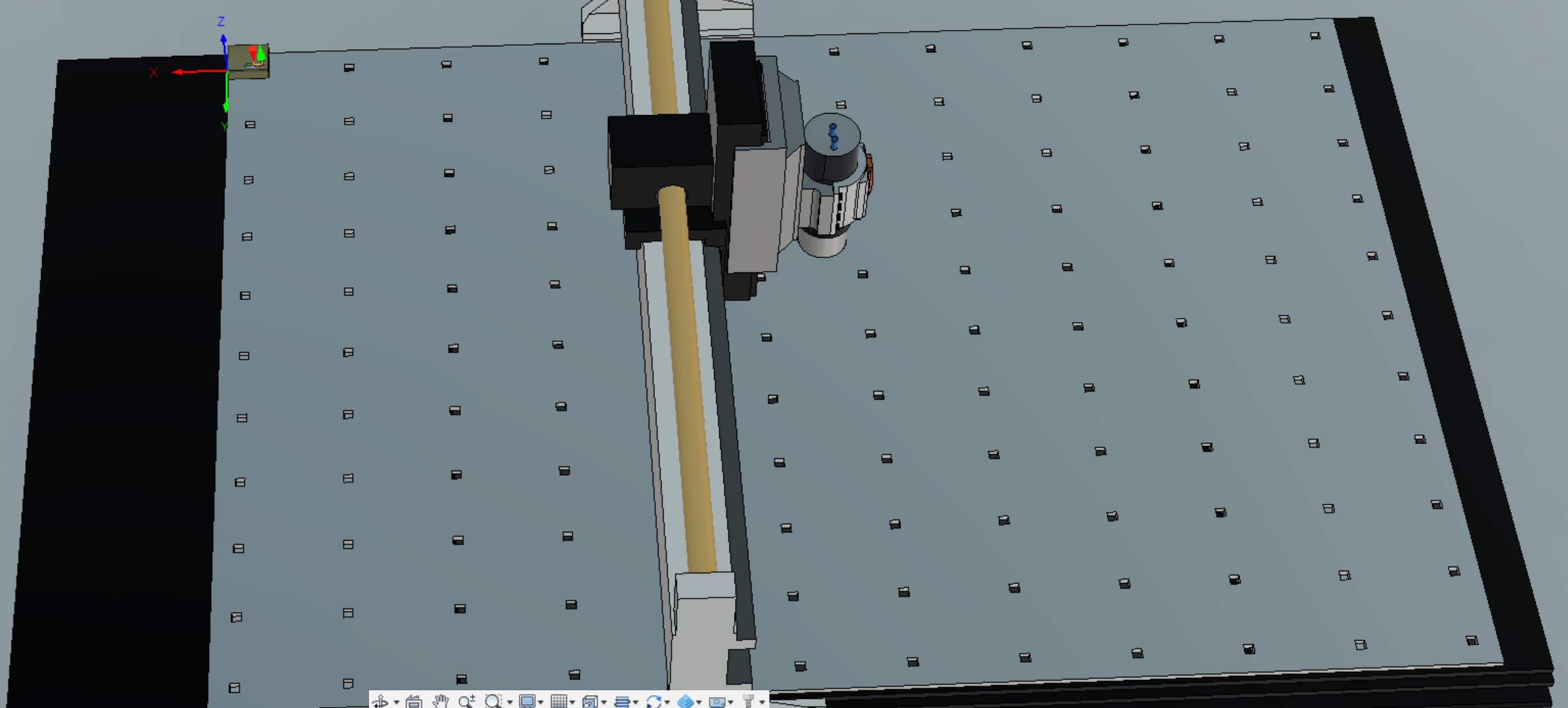
I think your X and Y normals are pointed in the wrong direction on your drawing.
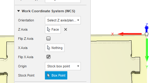
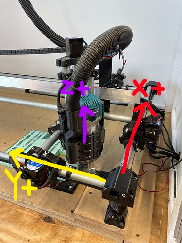
You need to rotate your direction arrows so they align with your part. Make it look like this:
Then you will always have mirrored results.
By having the machine home to the front, right corner, you are changing the coordinate system, and everything will be mirrored. I did a quick search, and did not find any way to redefine the coordinate system in Fusion 360. See right hand rule for the coordinate system Fusion 360 expects.
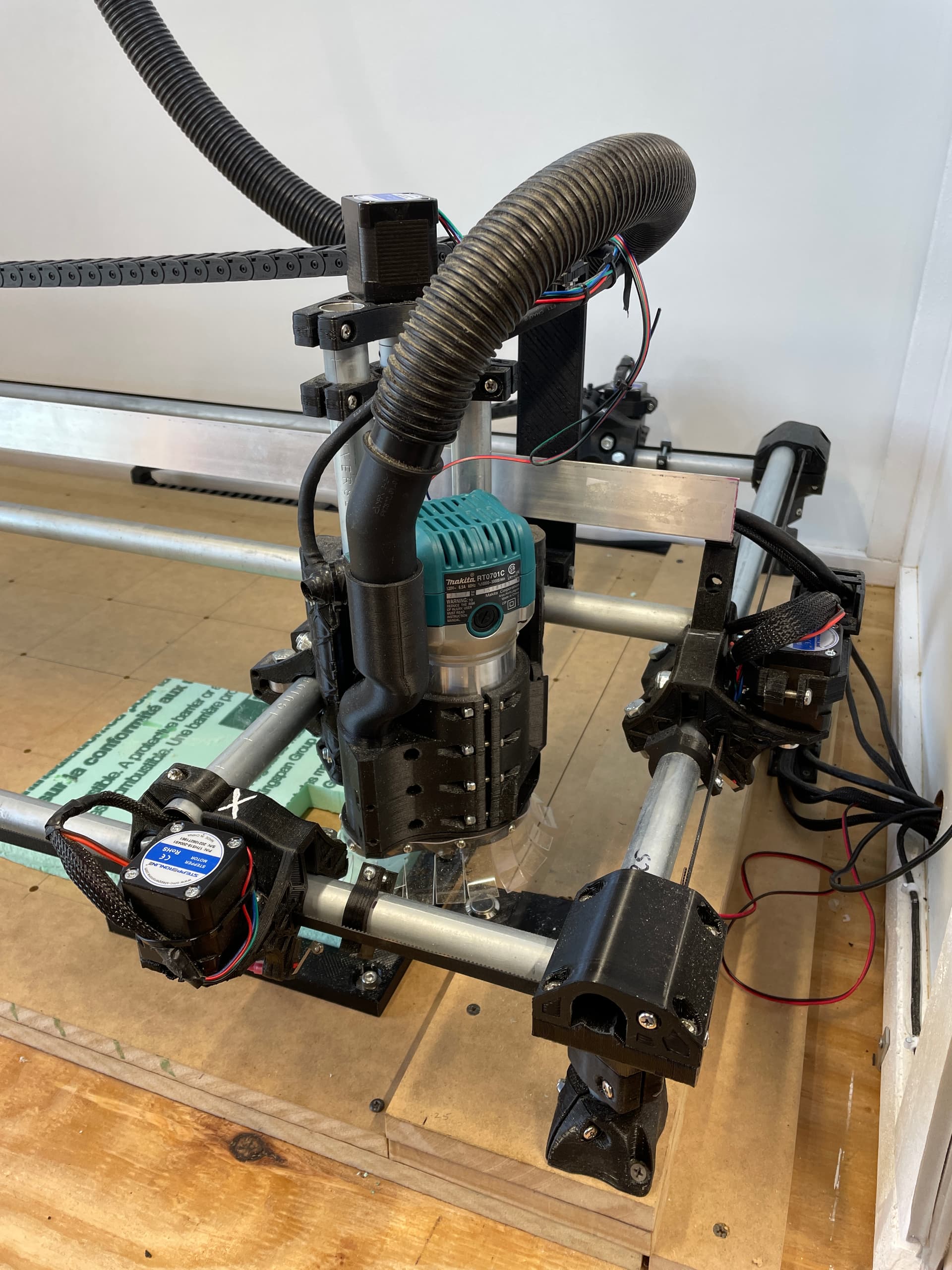
I’m not sure of your mount issues, but your core is mounted rotated compared to all the other machines. I don’t know if this was necessary for the mount, or if you assembled the machine wrong.
From a coordinate system point of view (and therefore Fusion 360 point of view), you could define the back right corner as home. Then you will need to define your coordinate system in Fusion 360 for each job:
While workable, I think this rotation of coordinate system will be a pain, and it will be better to solve the problem mechanically by solving the mounting issue.
Edit: With the back right corner as home, you could just rotate everything in your brain WRT setting up the job rather than changing the coordinate system in Fusion 360. Still a pain.
What @jeffeb3 is describing is generally referred to as the “right hand coordinate system” and is the standard for virtually all CNC configurations. My first home-built CNC was a “Phlatprinter” that had the tool come up from under the table. It took me a while to realize why everything came out correct sizes, but lettering was mirrored. With Z “backwards” I also had to flip X travel direction and homing location to get things to match up.
As pointed out, unless positive X move the tool from left to right, you’re going to get mirrored results. If you need the switch to stay in that position, then reverse the X direction of travel and configure the firmware for homing X to Max. You’ll also want to set a correct amount of X travel so that the X axis zero position ends up within the machine’s work envelope (and I’d go ahead and set Y and Z travel amounts as well).
Using the back Right corner as you said inverts the job.
At this point, I think I should configure the machine how it was make to be configured and give up on using this mount.
Yes, if you can configure your machine as it was intended, that is by far the best solution. I don’t think I was clear about my alternate suggestion. In order to use the back left corner, you have to make that corner the home position. You have to reverse your Y movements and therefore put your endstop in that corner. You cannot just change the coordinate system in Fusion 360.
When you flip the stepper movement of both X and Y, you are rotating the coordinate system 180 degrees, but will still be the right-hand coordinate system that Fusion 360 expects.
and give up on using this mount.
Just to be clear, if you install the core the way Ryan designed the machine, you are saying this mount does not work? If so, would mirroring the mount when 3D printing it solve the issue?
That looks weird to me. Like the truck that you have labelled as “X” is on what Id have considered my Y axis.
The trucks look correct relative to the core.
I think you have the X and Y axes reversed, which will also result in mirror image results.
In the Build instructions it says to temporarily install the Y rails to straighten the corners. Those are the lower 2 rails, so that should be the Y axis. The higher rails are the X axis.

Another option is to pretend you are standing on the right side of the machine. If you did to that, and swapped X and Y, would you have these?:
To make that work, he would need to swap the X steppers and the Y steppers at the control board, but that is a lot easier than redoing the mount. Another option that comes to mind is to make an alternate mount for the switch so it homes on the left, but leave the router mount in the current configuration.
Thanks Barry. That is much clearer than my text. That would work. You just have to remember that’s how your machine is set up when you get back to fusion.
Take a look over one of my older topics. Might help you set up what you want.
https://forum.v1e.com/t/homing-at-different-corners/30787/10