Was adjusting my build to fit new rails on my table the other day. When adjusting the X tubing, my XZ Main part broke where the bolt tensions the fit to the tubing. This isn’t the first time this has happened and it wasn’t a layer adhesion failure as it broke diagonally across the layers. This part was also reprinted with a 65% infill and still failed. If I had to guess I’m adding too much tension to these bolts. At the same time I feel that this junction should be solid as a rock so the difference between too tight and too loose is always going to be a fine line.
I now have the ability to print polycarbonate on my 3D printer. Ploymax PC to be exact. Has anyone out there tried PC on their build? Is there any negative to using it? Would it solve this problem?
That depends, what have you identified the problem as?
My opinion is that you’re probably way over tightening the bolts. Those bolts are capable of snapping about anything that you can 3D print, so polycarbonate is just going to move the weak point somewhere else, and you’ll snap other pieces instead. The strength of the pieces isn’t usually a weak point of this design, so I don’t think it’ll get much better working results, but higher temperature resistance might let you run the motors hotter, or let you work in a hotter environment.
I remember reading that polycarbonate filament has a significantly higher rate of shrinkage, so if you do go this route, you’ll need to print the parts a little larger to accommodate this.
Mostly, I think the problem will be resolved though if you just don’t tighten the bolts any more than they need to be. Remember, there is supposed to be a gap between the parts. It was designed that way.
Edit: Also, in the instructions, Ryan repeatedly says that too loose is better than too tight. Rock solid isn’t the goal with those junctions, just tight enough not to wiggle is what’s needed.
I always think of a tea-chest (which dates me a bit) - or now a cardboard box. All of the components are too light until they are assembled and the entire structure becomes incredibly rigid.
When you are folding a box it doesn’t matter how many layers of tape you put over the joint, it won’t make it any stronger - same here, the bolts are just holding the pieces in position so the entire structure can do the work.
I always remember that the screws are chosen to have enough surface area, and to have one size to keep the sourcing simple. But mechanically, they are much tougher than the application. So tightening them to their potential is going to be breaking stuff.
This doesn’t answer your question directly. I don’t know much about PC. A lot of people want to use ABS or PETG, but those actually are softer (and less brittle). PLA is brittle, but it holds firmly until it breaks. If you can just keep from breaking it, the joint will actually wiggle less than PETG (all else equal). Does PC get past this limitation? IDK. I think we need a mechanical engineer or at least someone to look up the numbers.
Kinda what I thought. Those parts just flex instead of put up a fight when tightening too much. I think that’s what’s messing with me. Still probably going to reprint in PC just to see how it comes out.
The rigidity is higher than PLA or polycarbonate. It is 2.6x more rigid than PC with 90% the strength. Rigidity is the most important factor since it increases cut accuracy.
The shrinkage is basically non existent due to the carbon fiber content.
It was just as easy to print as PLA - any garden variety 3D printer can print it as long as it has a hardened nozzle.
The cost is 25% lower than PC.
There is no risk of getting a cheap / off brand PC which is usually diluted with PETG and is nowhere near as strong as true PC.
It has a higher melting point than PLA, allowing for more wiggle-room when dealing with hot stepper motors.
I printed with a 0.8mm nozzle and 0.4mm layer height as this increases part strength & reduces print time.
I did a 100% infill and salt-packed the parts into a small bread loaf pan which I then annealed in an oven. I found that heating to a high temperature over the glass transition point, then turning off the oven and allowing to cool for several hours, provided basically the same strength as fully remelting but without the downsides of fully remelting (mainly a bad surface finish). The parts sounded like they were made of ceramic after annealing (very “clacky”) .
I bought a box of rock salt for $2 bucks and stuffed it into a blender to get the salt powder.
Annealing drastically bumps up their strength, rigidity, and temperature resistance.
Due to the carbon fiber they annealed quite nicely as it helps it hold its shape and fights shrinkage.
Parts that weren’t structural and weren’t in contact with heat I printed with PLA to reduce cost (and those were annealed as well).
An even better option is PC+CF, which has more strength and rigidity but is likely more difficult to print:
I went with PETG+CF since it was substantially less expensive and achieved near the same strength/rigidity but with no hassle printing it. I am currently using a 48"x96" LR2 build to cut hard woods with bits as large as 1" x 0.5" cut depth x 25mm/s. In other words it works quite well.
If you don’t want to hassle with printing them yourself, 3Dxtech does offer a printing service which might be pricey (I’ve never used it) but it would cut out the majority of the hassle & ensure quality prints:
Interesting. My build volume is only X2’xY4’ but I use the machine quite a bit for domestic (US) hardwoods and some exotics. While my machine is very rigid due the shorter X axis and grooved rails it gets alot of chatter when profiling arcs and circles when encountering certain grain orientations. Especially in hard, open grained wood. I then have to go in with a gouge to clean it up which isn’t ideal.
Do you have this problem with your machine? Does the CF PETG make a difference? Also, what bits are you using and do they come in a 1/4" shank? Thanks!
The high rigidity of the carbon fiber petg made a massive difference to the rigidity of the machine. Doing circular cuts for example had a lot of slop in them even for small bits at low speeds. Now I run much larger bits at higher speeds and it comes out so accurate there is no visual inaccuracy. I also haven’t noticed any chattering even cutting hard maple with large flattening bits. This was very surprising to me given the size of the machine I built which I figured would have huge trade-offs in accuracy/size. That’s not the only changes that I made, though.
I also spent a lot of time with a square making sure everything was perpendicular and torqued evenly. I added a V groove track for the wheels to roll in which drastically increased the accuracy of the Y axis movements and also reduced friction. I removed the vacuum port and added a second X motor (I once had the X axis stick due to dust buildup), and went with the biggest nema 17’s I could find which were 92 oz/in. I dropped the 12v power supply in favor of a 24v one (higher voltage drastically increases stepper motor torque especially at higher speeds). I added heatsinks to the motors so I could run them hard at 100% their rated limit. I went with 200 steps/revolution as they are higher torque and have a better rpm/torque curve than 400. I used half-step microstepping as high microstepping drastically reduces the torque of the motor. The theoretical accuracy is 0.2 mm which is well below visual detection and below grain tear-out.
With these changes, I can run the machine so hard the belts visibly droop under the load (I don’t run them that hard but as a test-case it shows all the other weak-links have been eliminated and the new weak point is the belts). Movement commands I run at 5 inches per second and cuts I run at roughly 1 inch per second even with my biggest bits. This is the fastest I am comfortable running them although I could theoretically go faster. 5 ips is so fast it doesn’t give you a lot of reaction time if it is doing something wrong. The LR2 is capable of some pretty amazing stuff but not with the basic kit that is available. It took quite a lot of modifications to get it this far.
This is by far the best surfacing bit I have found so far. The carbide blades last a long time and are cheap and easy to replace. The surface finish is a bit lacking but nothing that a bit of sanding with 80 grit can’t solve.
I was one of the beta tester of the Primo and I printed the trucks and Core with CF PLA a lot more rigidity then just PLA. I didn’t had enough Polycarbonate CF to print the core otherwise I would. Not mentioning we printed 3 Core pieces
All parts still standing even after cutting Steel with precision.
CF PLA is a great option I evaluated as well. It has about 110% the stiffness of PETG+CF but 86% the strength. It’s also a bit cheaper at about 85% the cost. I was personally reluctant to use it since I have had issues with PLA melting. I’ve had dust boots melt and things in contact with stepper motors soften and deform as well. For things not in contact with heat I think it would be a good option.
If I build another one I will probably spend the bit extra on some polycarbonate+CF since it has some really impressive numbers in every category from heat resistance to strength to stiffness:
This particular kind of PC is supposed to be easier to print and doesn’t require a heated chamber which is a big plus for me.
It’s amazing that a 3D printed CNC can cut steel. Do you have some measures of the accuracy by chance?
Dude you are next level! This is all super useful. Your bit recommend is much appreciated. I’ll check it out since my Freud mortising bit exploded on a rouge nail!
This is an option I had not considered. Based on my EXTREMELY basic printing knowledge and what the comments from others suggest is that the LR2 is designed in such a way that strength (PETG) is secondary to rigidity (PLA). Heat won’t be an issue for me since I’m never going to push my machine like BleepBleepBloop does. But the motors do get hot and could potential warp my parts over time. The PC I have is still sealed and from what I understand is extremely hydroscopic. No dry box at the shop means it’d sit around and get ruined.
So… based on this. Should I get the PETG+CF or the PLA+CF? We’re only talking a $10 USD difference for a 750g spool so either is fine. Both are easy to print. Interested in thoughts on this. I have a feeling I can’t go wrong with either.
I ran this by my brother who is a plastics engineer and we’re going with the CF-PETG for a couple reasons.
First it’s way more rigid than regular PLA. CF-PLA is even more rigid but not by a whole lot more than the CF-PETG. Second is the glass transistion temp. CF-PETG is a full 20 degrees C higher than the CF-PLA. That’s piece of mind knowing that if my motors really heat up parts won’t fail. Third is cost. Both the CF-PLA and CF-PETG are in the $50-60 price range for 750g. CF-PC (that my machine can print) hovers around $90. I’d also be pushing my 3D printer close to the edge of its operational ability with this material - even regular PC. That machine breaks, I don’t have a backup.
Anyways thanks for your help and insight everyone! Very helpful.
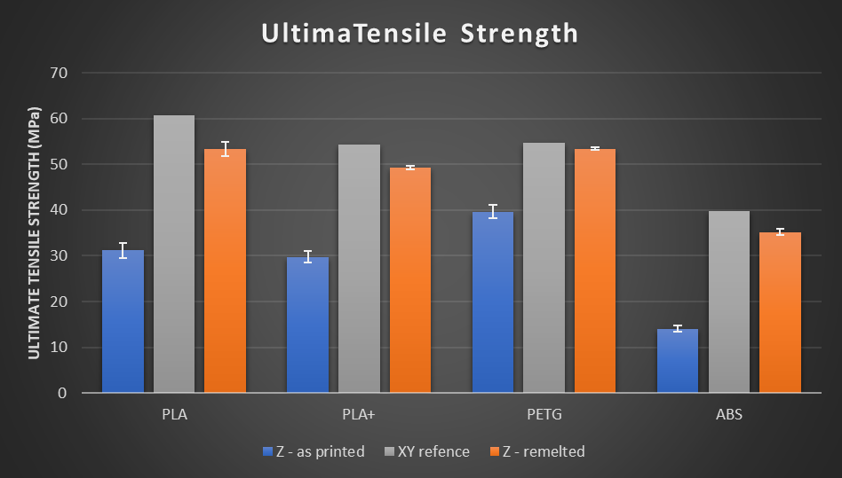
I don’t know how much effort makes sense for you, but if you want maximum strength I highly recommend salt-packing the parts and remelting them in an oven (especially if they tend to break along the layer lines). Here is a good chart that shows the difference:
Basically it’s an increase from 40 to ~53 which is a roughly 30% strength increase. The cost to do this is low, but it is time intensive. It’s a few dollars in salt, a small baking pan, and a blender to get salt powder. You just put some salt in, add the part, then cover it in salt and pack the salt down into every crevice really well. Some people do a full remelt but I found some figures online showing that if you raise it substantially above the glass transition temperature it achieves very near the same strength but you don’t end up with the porous surface finish.