Ok so here is my issue. My machine is fully assembled and working however while making the spoil board I found that the holes I was doing were not fitting the pvc pipe. I programmed in Vectric for the hole to be 21.5 mm diameter holes and that should have been a perfect fit but they would not fit at all and have had to jump it up to 21.67 mm and while one fits the others fit and tight or not at all. So here is what I have done to find the issue.
I checked square of the machine and it is spot on
I verified all distances between the rails is the same
I homed the machine and moved each rail 20mm and measured the distance of both sides and it is right no
After the job finished I measured again and still spot on
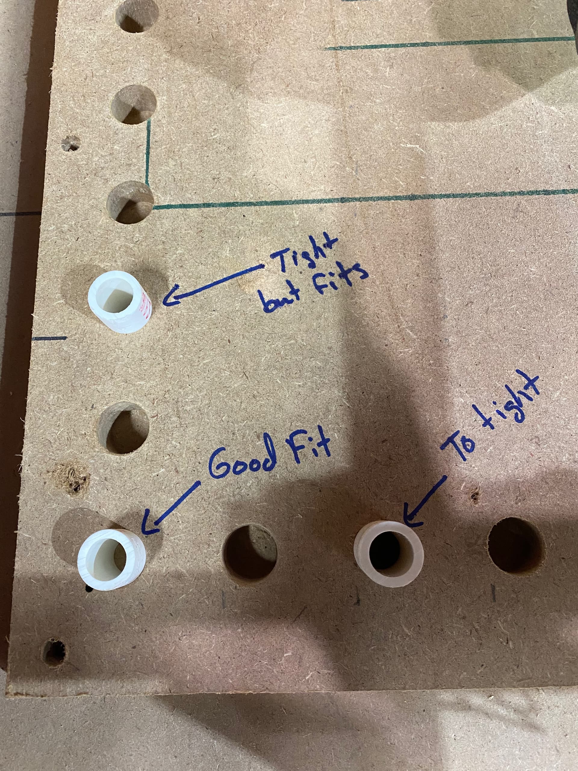
I am including some pics to show what I’m talking about.
As you can see my first pocket fits nicely but after having to constantly increase the size. The pockets up the left (y) are tight but I can get them in and out with pliers. The ones along the bottom (x) will not fit. They are all the same size in Vectric.
Am I wrong to think that I should be able to get a better accuracy. I would think even if I was out of square the pockets would be the same size just not square to each other of a longer span. Also not sure if this is a software or hardware issue. Any help would be greatly appreciated because I’m tired of running in and out of the house trying to increase the pockets until they fit. Thanks in advance.
I would measure the bit with your calipers and verify the diameter matches what is says it is. Then plug that value into Estlcam. Sometimes they are a bit off (pun intended). With a variance that small, I’d bet thats it. Otherwise, it might be your steps per mm, due to variations in drive pulley quality.
I will give it a look and see what I can find. Anybody know if repetier host of cncjs has the ability to adjust the steps per inch if that is what my issue is?
I’m running at around 80 “ pm and I do not think a finishing pass will matter. I have rerun the code taking off .03 mm several times and I still end up with incorrectly sized holes. If I had to guess your idea of the steps being out of wack are accurate being that it gets worse the farther out from first hole you get. But who knows. I’m going to try using some paper and a v bit d put a hole in it and move a distance and put a hole and measure.
Uh, I got the answer: One of the grub screws is loose! Then one stepper drags the other one behind and it seems like it all works but it doesn’t. It’s always those pesky little fuc… funions…
/edit: maybe it isn’t, but my intuition tells me it is.
Are you talking about the set screws on the pulleys? Because while I can check them I hit them all with thread locker and tightened them down pretty good.
Yeah, those. Check them, please. We had two cases where this was the reason, once on my own and once with a guy who 3D-printed a bowl. Might be more, but those two I remember.
I will check them tonight along with verifying the steps per inch is accurate. Does anybody know if the steps per inch is coded into firmware or do we have to set it some place else?
I need to perform a few more tests but I made a mark in a piece of cardboard with a v bit and picked it up and moved 80 mm and made a mark again and it seems to be off by 1mm roughly. So if that is the case I need to increase the number of steps per mm slightly. I will do a few more tests to confirm
I’m at a loss. My steps per mm does not stay after a restart and I cut an 80mm x 80mm with an outside cut and got an 80.93 x 80.93 square so that would indicate it cutting bigger than it should. I did tighten up the belts to see if maybe they were to loose. I’m not sure if the increase in size is due to me tightening up the belt or if my original measurements of it being 1mm under was wrong
So here is my current questions.
Why is the first hole fit so much better than every hole after that? Each pocket should be the exact same so if one fits they all should.
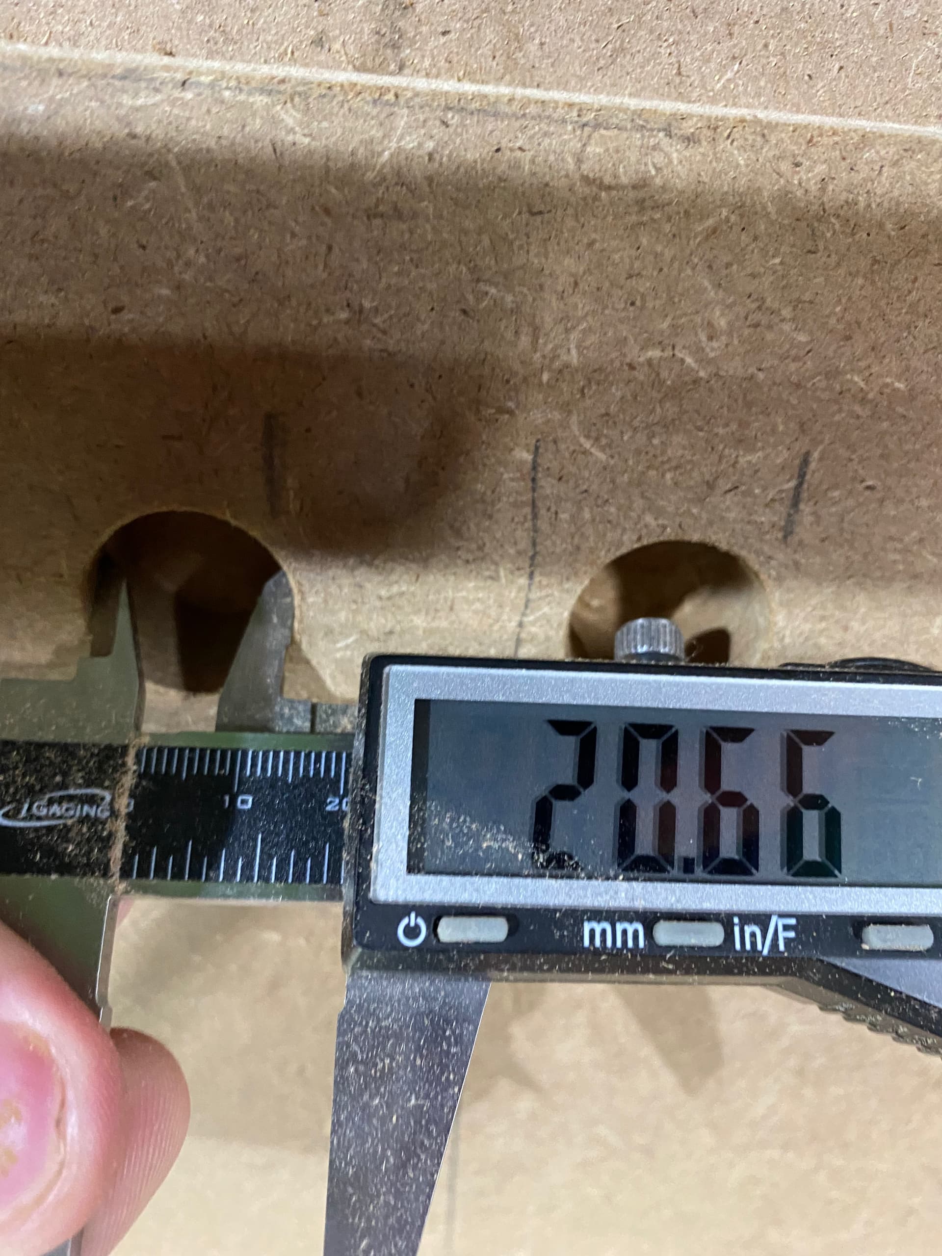
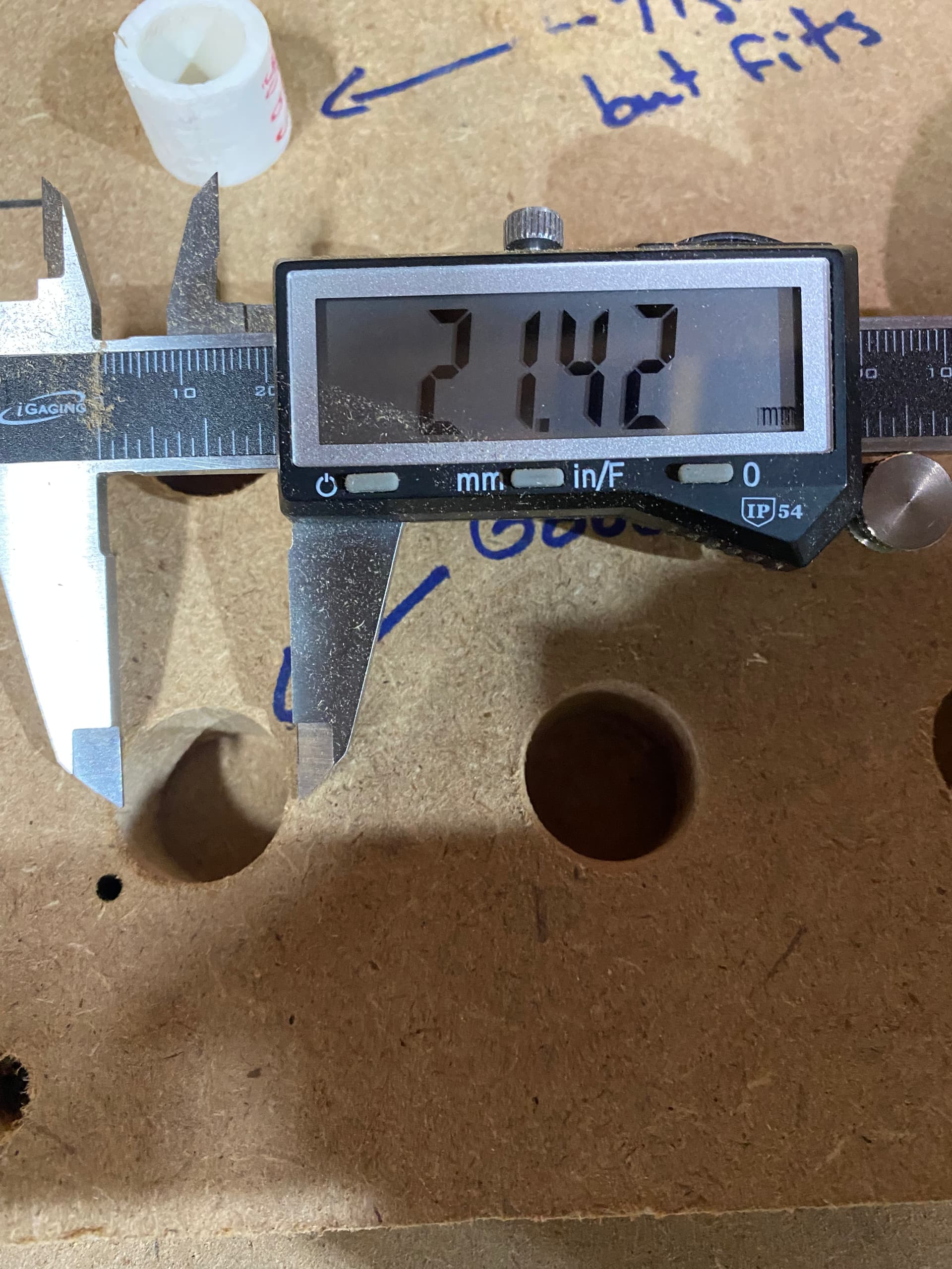
Why does a circle of 21.67 mm not fit on something that has a max 21.53 mm size.
How do I get the new steps per mm to stay after a reboot?
once you set your step/mm, under “Configuration”, scroll to the “store settings” menu item to save them permanently. Alternatively, from the console, send the M500 command.
Ok. So here is what I found so far or what I have done.
I checked my bits and one was .247 and the other was .2485. So I do not believe the bits are the issue. They are close enough to .25 as to not cause such a drastic difference and if they were the issue I would think all the holes would be out by the same amount
I tightened all my belts to reduce any slack
I did find 3 bearings that were hardly touching. One on each of the x blocks and 1 on a y block. I tightened them down so they are making contact and verified everything is still square to within a hair of a mm or at least the same line on my tape measure
I sunk my v bit into some plywood 1mm raised it and moved it 80 mm and sunk it back 1mm and repeated that with 120 mm. I measured out 80.02 and 120.02 so I’m guessing my steps are right on.
I ran my code again and it seemed to shave a hair off of all the holes. Now all the holes running up the Y axis fit my pipe while all the holes along the X axis are still tight.
I also found that the router is perfectly square to the table in the front right to top left and off .4 degrees in the front left to back right.
I hope all this info might set off a lightbulb in somebody that has a lot more experience at this then me.
So with all that said why are some holes fitting and others are not and with a piece of pipe with a max diameter of 21.54 mm needing me to make a 21.67 mm diameter pocket in Vectric in order for it to fit.
On a primo, the fact is the length of belt between the motor and ends changes depending on position. Given a finite amount of belt flex, the amount of error in the plus and minus directions is not constant. Near the origin, shorter effective belt lengths strongly resist motion in the positive direction, but flex in the negative direction is maximized. Centered on the workspace the flex is even in all directions since the belt lengths are equal.
The result is the gantry does not have uniform belt stretch across xy. I think the threaded belts we use have non linear tension as well, so predicting the outcome may be counter intuitive. I suspect though, this may be a cause of what you observed.
A practical approach to reducing error caused by the non-uniform belt k, is reduce workspace to only what is required, increasing belt tension, and/or run lower bit loadings (higher rpm, lower feed rate, less doc, less step over). An software correction may be possible… would require post processing with a map of the measured flex in x and y.
However like all things Cnc, the result is the sum of the parts. There may be other things adding to make the result, like pipe flex, bearing eccentricity, etc. So no guarantees anything I mentioned will help, hehe.
So if I am understanding what you are saying is I should tension my belts a bit more, reduce my feed rate by maybe 10% and decrease my step over from let’s say 40% to 30% to decrease the strain per cut also increase my RPMs to make up for the reduced feed rate.
These steps may take out some inaccuracies due to variations in the belt on each side of the motor.
That is more or less correct. There is a limit to how much rpm you can use and how low the federate can go before you start burning up bits. So it is better to use small changes one at a time in that direction vs 25% changes all at once. Chipload and surface speed are important to look at when setting up cam, to avoid burning bits as you dial things in.
I wouldn’t change step per mm as for a less than 1 mm deviation step per mm seems you have configured seems to be good.
step per mm are calculated by that formula:
steps/mm = (motor steps per rev)∗(driver microstep) / (belt pitch)∗(pulley number of teeth)
I do not plan to change my steps per inch now that I know they were only off by .02 mm over 80mm and that is well within a margin of error on my part in measuring.